Page 131 of 232

on the accelerator in each gear. Do not rock the vehicle for more than a
few minutes, because it could damage the vehicle.
Do not rock the vehicle if the engine is not at normal operating
temperature or damage to the transaxle may occur.
Do not rock the vehicle for more than a few minutes or damage
to the transaxle and tires may occur or the engine may overheat.
Always set the parking brake fully and make sure the gearshift is
latched in P (Park). Turn off the ignition whenever you leave
your vehicle.
If the parking brake is fully released, but the brake warning lamp
remains illuminated, the brakes may not be working properly.
See your dealer or a qualified service technician.
Driving with a 4±speed automatic transaxle
Your automatic overdrive transaxle provides fully automatic operation in
either D (Overdrive) or 3 (Third). Driving with the shift selector in D
(Overdrive) gives the best fuel economy for normal driving conditions.
For manual control start in 1 (First) and then shift manually.
To put your vehicle in gear, start the engine, depress the brake pedal,
then move gearshift lever out of P (Park).
Hold the brake pedal down while you move the gearshift lever
from P (Park) to another position. If you do not hold the brake
pedal down, your vehicle may move unexpectedly and injure someone.
Driving
131
Page 135 of 232

When parking, do not use the gearshift in place of the parking
brake. Always set the parking brake fully and make sure that the
gearshift is securely latched in Park (P). Turn off the ignition
whenever you leave your vehicle. Never leave your vehicle unattended
while it is running. If you do not take these precautions, your vehicle
may move unexpectedly and injure someone.
DRIVING THROUGH WATER
Do not drive quickly through standing water, especially if the depth is
unknown. Traction or brake capability may be limited and if the ignition
system gets wet, your engine may stall. Water may also enter your
engine's air intake and severely damage your engine.
If driving through deep or standing water is unavoidable, proceed very
slowly. Never drive through water that is higher than the bottom of the
hubs (for trucks) or the bottom of the wheel rims (for cars).
Once through the water, always try the brakes. Wet brakes do not stop
the vehicle as effectively as dry brakes. Drying can be improved by
moving your vehicle slowly while applying light pressure on the brake
pedal.
Driving through deep water where the transmission/transmission
vent tube is submerged may allow water into the transmission
and cause internal transmission damage.
VEHICLE LOADING
Before loading a vehicle, familiarize yourself with the following terms:
²Base Curb Weight:Weight of the vehicle including any standard
equipment, fluids, lubricants, etc. It does not include passengers or
aftermarket equipment.
²Payload:Combined maximum allowable weight of cargo, passengers
and optional equipment. The payload equals the gross vehicle weight
rating minus base curb weight.
²GVW (Gross Vehicle Weight):Base curb weight plus payload
weight. The GVW is not a limit or a specification.
²GVWR (Gross Vehicle Weight Rating):Maximum total weight of
the base vehicle, passengers, optional equipment and cargo. The
GVWR is specific to each vehicle and is listed on the Safety
Compliance Label on the driver's door pillar.
Driving
135
Page 142 of 232

Roadside coverage beyond basic warranty
In the United States, you may purchase additional roadside assistance
coverage beyond this period through the Ford Auto Club by contacting
your Ford or Lincoln Mercury dealer.
HAZARD FLASHER
Use only in an emergency to warn traffic of vehicle breakdown,
approaching danger, etc. The hazard flashers can be operated when the
ignition is off.
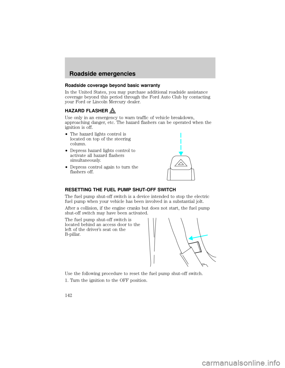
²The hazard lights control is
located on top of the steering
column.
²Depress hazard lights control to
activate all hazard flashers
simultaneously.
²Depress control again to turn the
flashers off.
RESETTING THE FUEL PUMP SHUT-OFF SWITCH
The fuel pump shut-off switch is a device intended to stop the electric
fuel pump when your vehicle has been involved in a substantial jolt.
After a collision, if the engine cranks but does not start, the fuel pump
shut-off switch may have been activated.
The fuel pump shut-off switch is
located behind an access door to the
left of the driver's seat on the
B-pillar.
Use the following procedure to reset the fuel pump shut-off switch.
1. Turn the ignition to the OFF position.
Roadside emergencies
142
Page 143 of 232
2. Check the fuel system for leaks.
3. If no fuel leak is apparent, reset the fuel pump shut-off switch by
pushing in on the reset button.
4. Turn the ignition to the ON position. Pause for a few seconds and
return the key to the OFF position.
5. Make a further check for leaks in the fuel system.
FUSES AND RELAYS
Fuses
If electrical components in the
vehicle are not working, a fuse may
have blown. Blown fuses are
identified by a broken wire within
the fuse. Check the appropriate
fuses before replacing any electrical
components.
Always replace a fuse with one that has the specified amperage
rating. Using a fuse with a higher amperage rating can cause
severe wire damage and could start a fire.
15
Roadside emergencies
143
Page 146 of 232

Fuse/Relay
LocationFuse Amp
RatingPassenger Compartment Fuse Panel
Description
5 10A Virtual Image Instrument Cluster, Lighting
Control Module (LCM RUN/START Sense),
Autolamp Light Sensor
6 10A Virtual Image Instrument Cluster, RF
Park/Turn Lamp
7 20A Power Point
8 20A Fuel Filler Door Release Switch, Trunk Lid
Relay
9 10A Air Bag Diagnostic Monitor, EATC Module,
Blower Motor Relay
10 30A Windshield Wiper Motor, Windshield Wiper
Module
11 10A Ignition Coils, Radio Interference Capacitor,
PCM Power Relay, Passive Anti-Theft
System (PATS) Transceiver
12 10A Lighting Control Module
13 15A Lighting Control Module (LCM): RF Turn
Lamp, Right Turn Indicator (VIC), RR Side
Marker Lamps, Tail Lamps, License Lamps,
LR Stop/Turn Lamps, Clock Illumination
14 20A Cigar Lighter
15 10A ABS Evac and Fill Connector
16 30A Moonroof Switch
17 Ð Not Used
18 10A Lighting Control Module
19 10A Lighting Control Module (LCM): Left
Headlamp, DRL
20 15A Multi-Function Switch: Flash to Pass, and
Hazard Warning Input to LCM
21 Ð Not Used
22 ÐÐ Not Used
23 10A Digital Transmission Range Sensor
24 10A Virtual Image Cluster-LF Turn Indicator, LF
Turn Signal
Roadside emergencies
146
Page 149 of 232

Fuse/Relay
LocationFuse Amp
RatingPassenger Compartment Fuse Panel
Description
5 10A Virtual Image Instrument Cluster, Lighting
Control Module (LCM RUN/START Sense),
Autolamp Light Sensor
6 10A Virtual Image Instrument Cluster, RF
Park/Turn Lamp
7 20A Power Point
8 20A Fuel Filler Door Release Switch, Trunk Lid
Relay
9 10A Air Bag Diagnostic Monitor, EATC Module,
Blower Motor Relay
10 30A Windshield Wiper Motor, Windshield Wiper
Module
11 10A Ignition Coils, Radio Interference Capacitor,
PCM Power Relay, Passive Anti-Theft
System (PATS) Transceiver
12 10A Lighting Control Module
13 15A Lighting Control Module (LCM): RF Turn
Lamp, Right Turn Indicator (VIC), RR Side
Marker Lamps, Tail Lamps, License Lamps,
LR Stop/Turn Lamps, Clock Illumination
14 20A Cigar Lighter
15 10A ABS Evac and Fill Connector
16 Ð Not Used
17 Ð Not Used
18 10A Lighting Control Module
19 10A Lighting Control Module (LCM): Left
Headlamp, DRL
20 15A Multi-Function Switch: Flash to Pass, and
Hazard Warning Input to LCM
21 Ð Not Used
22 ÐÐ Not Used
23 10A Digital Transmission Range Sensor
24 10A Virtual Image Cluster-LF Turn Indicator, LF
Turn Signal
Roadside emergencies
149
Page 151 of 232

Power distribution box
The power distribution box is located in the engine compartment. The
power distribution box contains high-current fuses that protect your
vehicle's main electrical systems from overloads.
Always disconnect the battery before servicing high current
fuses.
Always replace the cover to the Power Distribution Box before
reconnecting the battery or refilling fluid reservoirs.
If the battery has been disconnected and reconnected, refer to the
Batterysection of theMaintenance and carechapter.
The high-current fuses are coded as follows:
Fuse/Relay
LocationFuse Amp
RatingPower Distribution Box Description
Ð 175 Generator/Voltage Regulator
1 30A** Driver's Seat Module
2 30A** Passenger's Seat Module
3 40A** Ignition Switch
4 40A** Ignition Switch
5 40A** Driver Window
6 30A** Low Speed Cooling Fan
7 30A** Powertrain Control Module
MEGA
175A
PCM
PWR
RELAY
12 3 4
8
7
6 5
12
4 3
5
7
9
1110
12
14 136
8NOT USED
7BLOWER
MOTOR
RELAY6A/C
CLUTCH
RELAY4NOT
USED2
HORN
RELAY3HIGH
BEAM1STARTER
SOL
RELAY5
12
Roadside emergencies
151
Page 179 of 232

²If you do not allow the engine to relearn its idle trim, the idle
quality of your vehicle may be adversely affected until the idle
trim is eventually relearned.
If the battery has been disconnected or a new battery has been installed,
the clock must be reset once the battery is reconnected.
²Always dispose of automotive
batteries in a responsible manner.
Follow your local authorized
standards for disposal. Call your
local authorized recycling center
to find out more about recycling
automotive batteries.
CABIN AIR FILTER
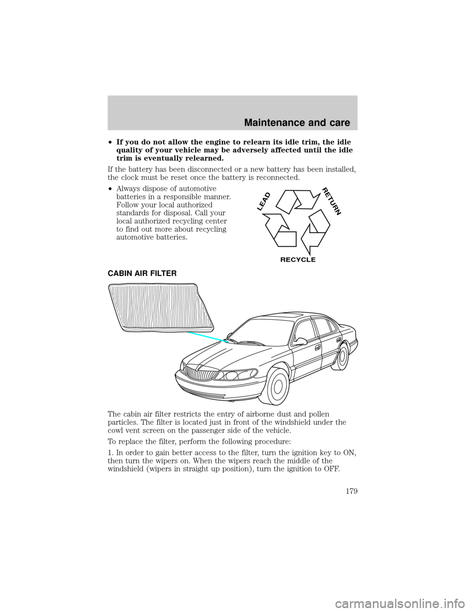
The cabin air filter restricts the entry of airborne dust and pollen
particles. The filter is located just in front of the windshield under the
cowl vent screen on the passenger side of the vehicle.
To replace the filter, perform the following procedure:
1. In order to gain better access to the filter, turn the ignition key to ON,
then turn the wipers on. When the wipers reach the middle of the
windshield (wipers in straight up position), turn the ignition to OFF.
LEAD
RETURN
RECYCLE
Maintenance and care
179