Page 220 of 267

Hoo
d Latc h an d Hinge s
Lubricate the hood latch assembly
and hood hinge assembly as
follows:
1. Wipe off any accumulatio n of
dirt o
r contamination on the
latch parts.
2. Apply multipurpose-type grease (NLGI No. 1 or 2) to
the hood latch pin cam.
3. Apply light engine oil to all pivot points in the release
mechanism.
4. Lubricate hood hinges with multipurpose-type grease
(NLGI No. 1 or 2).
5. Check the hood hinges and
latch mechanism to assure
they are working correctly.
Ai
r Conditionin g
Periodically have your Honda dealer check your air conditioning
system to be sure there has been
no loss in cooling output. See
your Honda dealer if you suspect
that the system is not performing
as it should.
Bod y Lubricatio n
Normal use of a vehicle causes
metal-to-metal movement at certain
points in the body. Noise, wear and improper operation at these points
will result when a protective film of lubricant is not provided.
For exposed surfaces such as door
checks, door lock bolts, lock striker plates, etc., apply a thin
film of light engine oil.
Any lubricant should be used
sparingly. After application, all excess lubricant should be
carefully wiped off.
The seat adjusters and seat track should be lubricated with water-
resistant EP chassis lubricant.
There are other points on the
vehicle body which may occasionally require lubrication.
Window regulators and controls are confined in the space between
the upholstery and the outside
door panel. Easy access to the
working parts may be made by
removing the trim. Door weatherstrips and rubber hood
bumpers should be lightly coatedwith a rubber lubricant.
Car e an d Maintenanc e
Page 221 of 267

Fron
t (4W D Only ) an d Rea r
Propelle r Shaf t
Lubricate the sliding yoke with
EP chassis grease. Lubricate
universal joints with grease
containing MoS 2 (molybdenum
disulfide-type grease) at the intervals shown in the
Maintenance Schedule. Also
check the propeller shaft
flange-to-pinion bolts for proper
torque of 64 N.m (46.3 Ib-ft).
Most lubrication recommendations
and procedures for four-wheel drive-
equipped vehicles are the same
for the corresponding components in conventional drive vehicles.
Exhaus t Syste m
Check the complete exhaust
system and nearby body areas for
damaged, missing, or
mispositioned parts, open seams, holes, loose connections, or other
deterioration that could allow
exhaust fumes to seep into the
passenger compartment or cause
heat build-up in the floor pan. Any
necessary corrections should be made immediately. For continuedsafety, exhaust system pipes and
resonators rearward of the muffler must be replaced whenever a new
muffler is installed.
Fue l Lin e an d Fue l Tank/Ca p
Inspect the fuel tank, cap and lines
for damage that could cause
leakage. Inspect the fuel cap and
gasket for correct sealing ability
and indications of physical
damage. Replace any damaged or
malfunctioning parts.
Driv
e Bel t
Check the belt driving the
alternator, power steering pump,
and air conditioning compressor.
Look for cracks, fraying, and wear. Replace as necessary.
Timin g Bel t
The timing belt should normally
be replaced at the intervals shown
in the Maintenance Schedule.
Valv e Clearanc e
Incorrect valve clearance will
result in increased engine noise and lower engine output, thereby
adversely affecting engine
performance.
Car e an d Maintenanc e
Page 222 of 267

Spar
k Plug s
Replace the spark plugs with the
type specified in the "Technical
Data" section.
Clutc h
Check the clutch play at the pedal.
Lubricate the clutch pedal bushing and clevis pin, at the intervalsshown in the Maintenance
Schedule, with water-resistant
chassis lubricant. If you hear a squeaking noise coming from the
area of the bushing or clevis pin at
the clutch pedal arm when the
clutch pedal is depressed,
lubricate it with water-resistant EP
chassis grease.
Check the fluid level in the clutch
reservoir at the interval shown in
the Maintenance Schedule. If the fluid is low in the reservoir, it
should be filled to the
maximum
level lin
e with DOT-3 or DOT-4
fluid.
Flui d o r Lubrican t Level s
Check the fluid or lubricant level in the brake master cylinder,
clutch master cylinder, power steering reservoir, rear axle,
engine and transmission, windshield washer reservoir and
engine coolant at specified
intervals.
Powe
r Steerin g
Check the fluid level in the power steering fluid reservoir as
recommended in the Maintenance Schedule. The fluid level should
be between the "MIN" and "MAX" marks on the reservoir.
Use only automatic transmission
fluid labeled DEXRON III.
Car e an d Maintenanc e
Page 231 of 267

Vehicl
e Identificatio n
Vehicl e Identificatio n
Numbe r (VIN )
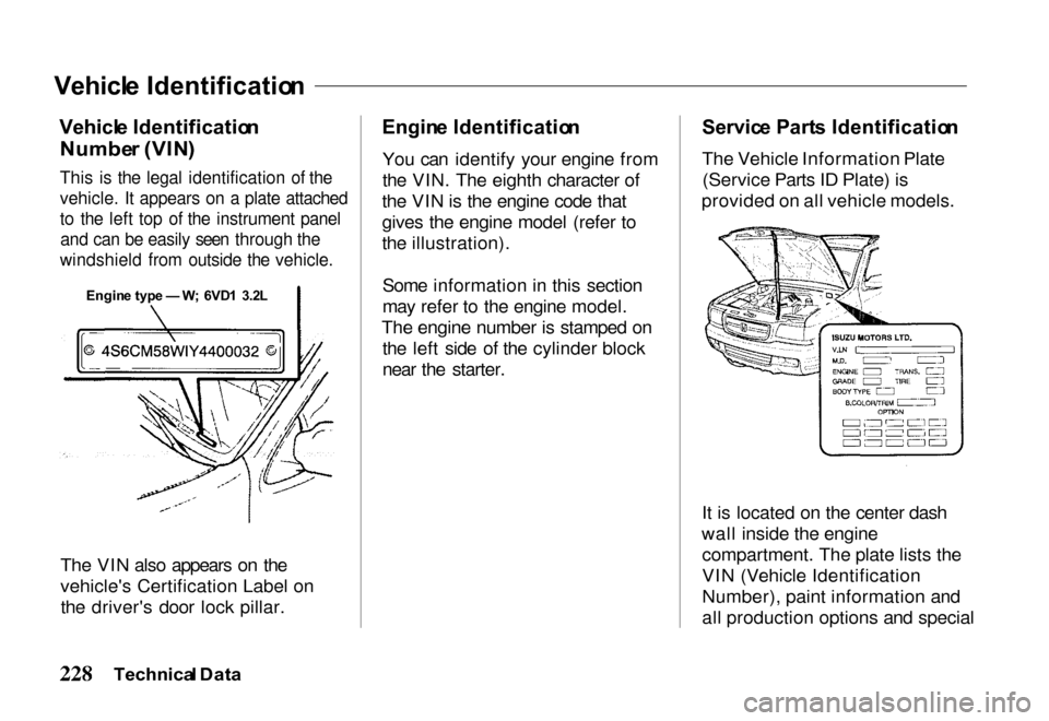
This is the legal identification of the
vehicle. It appears on a plate attached
to the left top of the instrument panel
and can be easily seen through the
windshield from outside the vehicle.
The VIN also appears on the
vehicle's Certification Label onthe driver's door lock pillar.
Engin
e Identificatio n
You can identify your engine from
the VIN. The eighth character of
the VIN is the engine code that
gives the engine model (refer to
the illustration).
Some information in this section
may refer to the engine model.
The engine number is stamped on the left side of the cylinder block
near the starter.
Servic
e Part s Identificatio n
The Vehicle Information Plate (Service Parts ID Plate) is
provided on all vehicle models.
It is located on the center dash
wall inside the engine compartment. The plate lists the
VIN (Vehicle Identification
Number), paint information and
all production options and special
Technica l Dat a
Engin
e typ e — W; 6VD 1 3.2 L
Page 232 of 267

equipment on the vehicle when it
was shipped from the factory. Be
sure to provide this information to
your authorized Honda dealer when it is necessary to order
parts.
Vehicl
e Loadin g
Vehicl e Loadin g Informatio n
The components of your vehicle are designed to providesatisfactory service only if the
vehicle is not loaded in excess of
either the Gross Vehicle Weight
Rating (GVWR) or the maximum
front and rear Gross Axle Weight
Ratings (GAWRs). These ratings are listed on the Vehicle
Certification Label located on the
left door lock pillar.
Your Honda dealer can advise you
of the proper loading conditions
for your vehicle. The use of
selected heavier suspension
components for added durability
purposes does not increase any of the weight ratings printed on the
Vehicle Certification Label. Maximu
m Fron t an d Rea r
Axl e Weigh t
The weight of the cargo load must be properly distributed over both
the front and rear axles. The
Certification Label shows themaximum weight that the front
axle (front GAWR) can carry. It also shows the maximum weight
that the rear axle (rear GAWR) can
carry. The GVWR represents the
maximum permissible loaded
weight of the vehicle and takes
into account the engine,
transmission, frame, springs,
brake, axle, and tire capabilities.
Actual loads on the front and rear
axles can only be determined by
weighing the vehicle. This can be
done at highway weight stations
or other such commercial weigh stations. Consult your Honda
dealer for assistance. The cargo
Technical Dat a
Page 239 of 267
Fuse
s
Fuse boxes are installed on the left side of the instrument panel and the right side of the engine
compartment. Each fuse box contains spare fuse
cartridges.
Replacing a fuse with one that has a higher ratinggreatly increases the chances of damaging the electrical system. If you do not have a replacement
fuse with the proper rating for the circuit, install one with a lower rating.
Technica l Dat a
NOTIC
E
Page 248 of 267

If you believe that your vehicle
has a defect which could cause a
crash or could cause injury or
death, you should immediately inform the National Highway
Traffic Safety Administration (NHTSA) in addition to notifying
American Honda Motor Co., Inc.
If NHTSA receives similar
complaints, it may open an investigation, and if it finds that asafety defect exists in a group of
vehicles, it may order a recall and
remedy campaign. However, NHTSA cannot become involvedin individual problems between
you, your dealer, or American
Honda Motor Co., Inc. To contact NHTSA, you may
either call the Auto Safety Hotline
toll free at 1-800-424-9393 (or
202-366-0123 in the Washington,
D.C. area) or write to:
NHTSA
U.S. Department of Transportation
Washington, D.C. 20590
You can also obtain otherinformation about motor vehicle
safety from the Hotline.
Emission
s Control s
The burning of gasoline in your vehicle's engine produces several
by-products. Some of these are
carbon monoxide (CO), oxides of
nitrogen (NOx), and hydrocarbons (HC). Gasoline evaporating from
the tank also produces
hydrocarbons. Controlling the production of NOx, CO, and HC isimportant to the environment.
Under certain conditions of sunlight and climate, NOx and HC
react to form photochemical
"smog." Carbon monoxide does
not contribute to smog creation,
but it is a poisonous gas.
Th e Clea n Ai r Ac t
The United States Clean Air Act sets standards for automobile
emissions. It also requires that automobile manufacturers explain
to owners how their emissions
controls work and what to do to
Owner Assistanc e
Reportin
g Safet y Defect s
Page 249 of 267

maintain them. This section
summarizes how the emissions
controls work. Scheduled
maintenance is on page 200.
Crankcas e Emission s
Contro l Syste m
Your vehicle has a Positive
Crankcase Ventilation System.
This keeps gasses that build up in the engine's crankcase from goinginto the atmosphere. The Positive
Crankcase Ventilation valve
routes them from the crankcase
back to the intake manifold. They are then drawn into the engine and
burned.
Evaporativ e Emission s
Contro l Syste m
As gasoline evaporates in the fuel
tank, an evaporative emission
control canister filled with charcoal adsorbs the vapor. It is stored in this canister while the
engine is off. After the engine is
started and warmed up, the vapor
is drawn into the engine and
burned during driving.
Exhaus t Emission s Control s
The exhaust emission controls include four systems: Fuel
Injection, Ignition Timing Control, Exhaust Gas
Recirculation, and Three-Way Catalytic Converter. These four
systems work together to control
the engine's combustion and
minimize the amount of HC, CO,
and NOx that comes out the
tailpipe. The exhaust emission
control systems are separate fromthe crankcase and evaporative
emission control systems. Fuel Injection System
The Fuel Injection System uses sequential multiport fuel injection.
It has three subsystems: Air
Intake, Engine Control, and Fuel
Control. The Engine Control Module (ECM) uses various
sensors to determine how much
air is going into the engine. It then
controls how much fuel to inject
under all operating conditions.
Ignition Timing Control System This system constantly adjusts theignition timing, reducing the amount
of HC, CO and NOx produced.
Owne r Assistanc e