Page 58 of 352

Instrument
s an d Control s
This section gives information about
the controls and displays that
contribute to the daily operation of
your Honda. All the essential
controls are within easy reach.
Control Locations............................
56
Indicator Lights...............................
. 57
Gauges.............................................. 62
Controls Near the Steering
Wheel........................................ 65
Headlights.................................... 66
Automatic Lighting Off
Feature......................................
67
Daytime Runnin
g Lights.............
67
Instrument
Pane
l Brightness.....
67
Turn
Signals................................
.
68
Windshield
Wipers.....................
. 68
Windshield Washers................... 70
Rear Window Wiper and Washer...................................... 70
Hazard Warning........................ 70
Rear Windo
w Defogger.............. 71
Steering Wheel Adjustment....... 72
Steering Wheel Controls................ 73
Cruise Control.............................. 73
Remote Audio Controls .............. 76
Keys and Locks................................ 76
Keys............................................... 76
Immobilizer System..................... 77
Ignition Switch............................. 78
Power Door Locks....................... 79
Remote Transmitter.................... 81
Childproof Door Locks............... 85
Tailgate......................................... 85
Glove Box..................................... 87
Manual Sliding Doors...................... 88
Power Sliding Doors........................ 89
HomeLink Universal Transmitter.................................. 95
Seats.................................................. 99
Passenger Seating....................... 99
Seat Adjustments....................... 100
Driver's Seat Power
Adjustments........................... 102
Armrests..................................... 103
Head Restraints......................... 104
Third Seat Access...................... 105 Moving the Second Row Bucket Seat............................ 106
Removing the Bucket Seats in the Second Row................. 108
Folding the Third Seat.............. 109
Power Windows............................. 112
Mirrors............................................ 115
Parking Brake................................ 116
Digital Clock................................... 117 Center Table................................... 117
Beverage Holder............................ 118
Sunglasses Holder......................... 120
Sun Visor......................................... 121
Vanity Mirror................................. 121 Rear Compartment........................ 122
Center Pocket................................ 122Coin Holder.................................... 122
Storage Box.................................... 123
Coat Hook....................................... 123
Accessory Power Sockets............. 124 Interior Lights................................ 125
Instrument s an d Control s
Page 82 of 352

Keys an d Lock s
ACCESSOR Y (I ) — In this position,
you can operate the audio system and the accessory power socket.
O N (II ) — This is the normal key
position when driving. All features and accessories on the vehicle are
usable. Several of the lights on the instrument panel come on as a test
when you turn the ignition switch from ACCESSORY to ON. STAR
T (III ) — Use this position
only to start the engine. The switch
returns to ON (II) when you let go of
the key.
The engine will not start if the Immobilizer System does not
recognize the key's coding (see page
77).
You will hear a reminder beeper if
you leave the key in the ignition
switch in the LOCK (0) or
ACCESSORY (I) position and open the driver's door. Remove the key toturn off the beeper. Powe
r Doo r Lock s
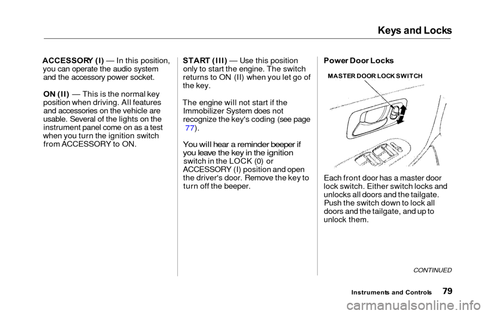
Each front door has a master door
lock switch. Either switch locks and
unlocks all doors and the tailgate. Push the switch down to lock all
doors and the tailgate, and up to
unlock them.
CONTINUED
Instrument s an d Control s
MASTE
R DOO R LOC K SWITC H
Page 127 of 352
Accessory Powe r Socket s
FRONT
Your vehicle has two accessory
power sockets. The front accessory
power socket is located under the center pocket. The rear socket is
behind the third seat on the driver's
side.
REA R
To use an accessory power socket,
pull out on the cover. The ignitionswitch must be in ACCESSORY (I)
or ON (II).
These sockets are intended to supply power for 12 volt DC accessories
that are rated 120 watts or less (10
amps).
When both sockets are being used,the combined power rating of both
accessories should be 120 watts or less (10 amps).
They will not power an automotive type cigarette lighter element.
Instrument s an d Control s
Page 258 of 352
Spark Plug s
3. Disconnect the wire connector
from the ignition coil by pushingon the lock tab and pulling on the
connector. Pull on the plastic
connector, not the wires. 4. Use a wrench to remove the
hexagon socket head cap bolt
holding the ignition coil. Remove
the ignition coil by pulling itstraight out.
5. Remove the spark plug with a five-eighths inch (16 mm) spark
plug socket. 6. Put the new spark plug into the
socket; then screw it into the hole.
Screw it in by hand so you do not
crossthread it.
CONTINUED
Maintenanc e
HEXAGON SOCKE T HEA D CA P BOL T
Page 259 of 352
Spark Plug s
7. Torque the spark plug. (If you do
not have a torque wrench, tighten
the spark plug two-thirds of a turn
after it contacts the cylinder head.)
Tightening torque:
13 lbf .
f t (1 8 N .
m,1. 8 kgf .
m )
Tighten the spark plugs carefully. A
spark plug that is too loose can
overheat and damage the engine. Overtightening can cause damage to
the threads in the cylinder head.
8. Install the ignition coil. Reinstall the hexagon socket head cap bolt.
9. Push the wire connector onto the ignition coil. Make sure it locks in
place.
10. Repeat this procedure for the other five spark plugs.
11. Reinstall the cover on the front cylinder bank while putting its
mounting clip in the hole on the
passenger's side. Secure the cover
by turning the heads of the two
holding clips one-quarter turn
clockwise with a flat-tipped
screwdriver.
Specifications :
NGK:
DENSO:
PZFR5F-11
PKJ16CR-L1 1
Spark Plug Gap:
0.04 in (1.1 mm)
Maintenance
NOTICE
Page 277 of 352

Lights
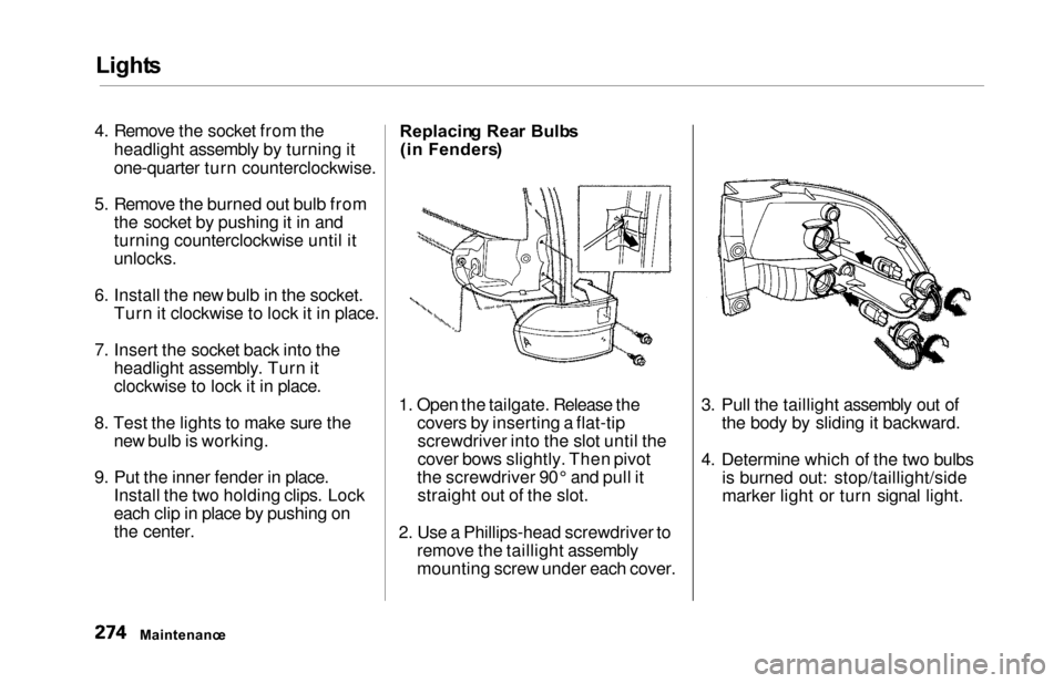
4. Remove the socket from the
headlight assembly by turning it
one-quarter turn counterclockwise.
5. Remove the burned out bulb from the socket by pushing it in and
turning counterclockwise until it
unlocks.
6. Install the new bulb in the socket. Turn it clockwise to lock it in place.
7. Insert the socket back into the headlight assembly. Turn it
clockwise to lock it in place.
8. Test the lights to make sure the new bulb is working.
9. Put the inner fender in place. Install the two holding clips. Lock
each clip in place by pushing on
the center. Replacin
g Rea r Bulb s
(i n Fenders )
1. Open the tailgate. Release the covers by inserting a flat-tipscrewdriver into the slot until the
cover bows slightly. Then pivot
the screwdriver 90° and pull it straight out of the slot.
2. Use a Phillips-head screwdriver to remove the taillight assembly
mounting screw under each cover. 3. Pull the taillight assembly out of
the body by sliding it backward.
4. Determine which of the two bulbs is burned out: stop/taillight/side
marker light or turn signal light.
Maintenanc e
Page 278 of 352
Lights
5. Remove the socket by turning it
one-quarter turn counterclockwise.
6. Pull the bulb straight out of its
socket.
Push the new bulb straight into
the socket until it bottoms.
7. Reinstall the socket into the light assembly by turning it clockwise
until it locks.
8. Test the lights to make sure the new bulb is working.
9. When reinstalling the taillight assembly, align and pop the snap
fasteners in place. Tighten the two
mounting screws and reinstall the
covers in place. Replacin
g Rea r Bulb s
(i n Tailgate )
1. Open the tailgate. Place a cloth on the edge of the taillight cover.Remove it by carefully prying in
the notch on its edge with a small
flat-tipped screwdriver.
2. Determine which of the two bulbs is burned out: taillight or back-up
light.
3. Remove the socket by turning it one-quarter turn counterclockwise.
CONTINUED
Maintenanc e
TAILLIGHT COVE R
Page 279 of 352
Lights
4. Pull the bulb straight out of its
socket.
Push the new bulb straight into
the socket until it bottoms.
5. Insert the socket back into the light assembly. Turn it clockwise
to lock it in place.
6. Test the lights to make sure the new bulb is working.
7. Reinstall the taillight cover. Replacin
g a High-moun t Brak e
Ligh t Bul b
1. Place a cloth on the middle edge of a part of the lens on the
passenger's side. Remove a part of
the lens by carefully prying on its edge with a small flat-tipped
screwdriver.
2. Use a Phillips-head screwdriver to remove the screw under the lens. 3. Pull the light assembly out of the
tailgate.
4. Remove the socket from the light assembly by turning it one-quarter
turn counterclockwise.
5. Pull the bulb straight out of its socket.
Push the new bulb straight into
the socket until it bottoms.
Maintenanc e SCRE
W