Page 964 of 1395

Troubleshooting
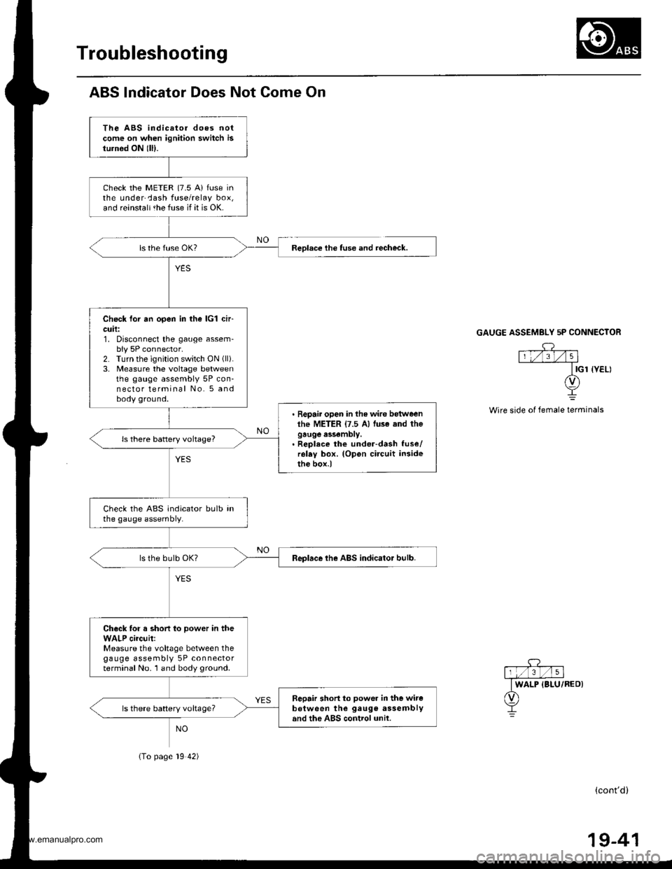
ABS lndicator Does Not Come On
The ABS indicator does notcome on when ignition switch isturnod ON lll).
check the METER {7.5 A} fuse inthe underCash fuse/relay box,and reinstaltthe fuse if it is OK.
Check for an open in the lcl ch-cuil:1. Disconnect the gauge assem-bly 5P connector.2. Turn the ignition switch ON (ll).
3. Measure the voltage betweenthe gauge assembly 5P con-nector terminal No. 5 andbody ground.
. Repair open in the wire betweenlhe METER {7.5 A) luse and thogauge assembly.. Reolece the under-dash fuse/relay box. (Opon circuit insidethe box.)
ls there battery voltage?
Check the ABS indicator bulb inthe gauge assembly.
Replace the ABS indicator bulb.
Check for a short to power in theWALP circuit:Measure the voltage between thegauge assembly 5P connectorterminal No. 1 and body ground.
Sepair short to power in the witeb€tween the gaug€ assemblyand the ABS control unil.ls there battery voltageT
Reolace the tuse and recheck.
(To page 19 42)
GAUGE ASSEMBLY 5P CONNECTOR
Wire side of female terminals
(cont'd)
19-41
www.emanualpro.com
Page 966 of 1395

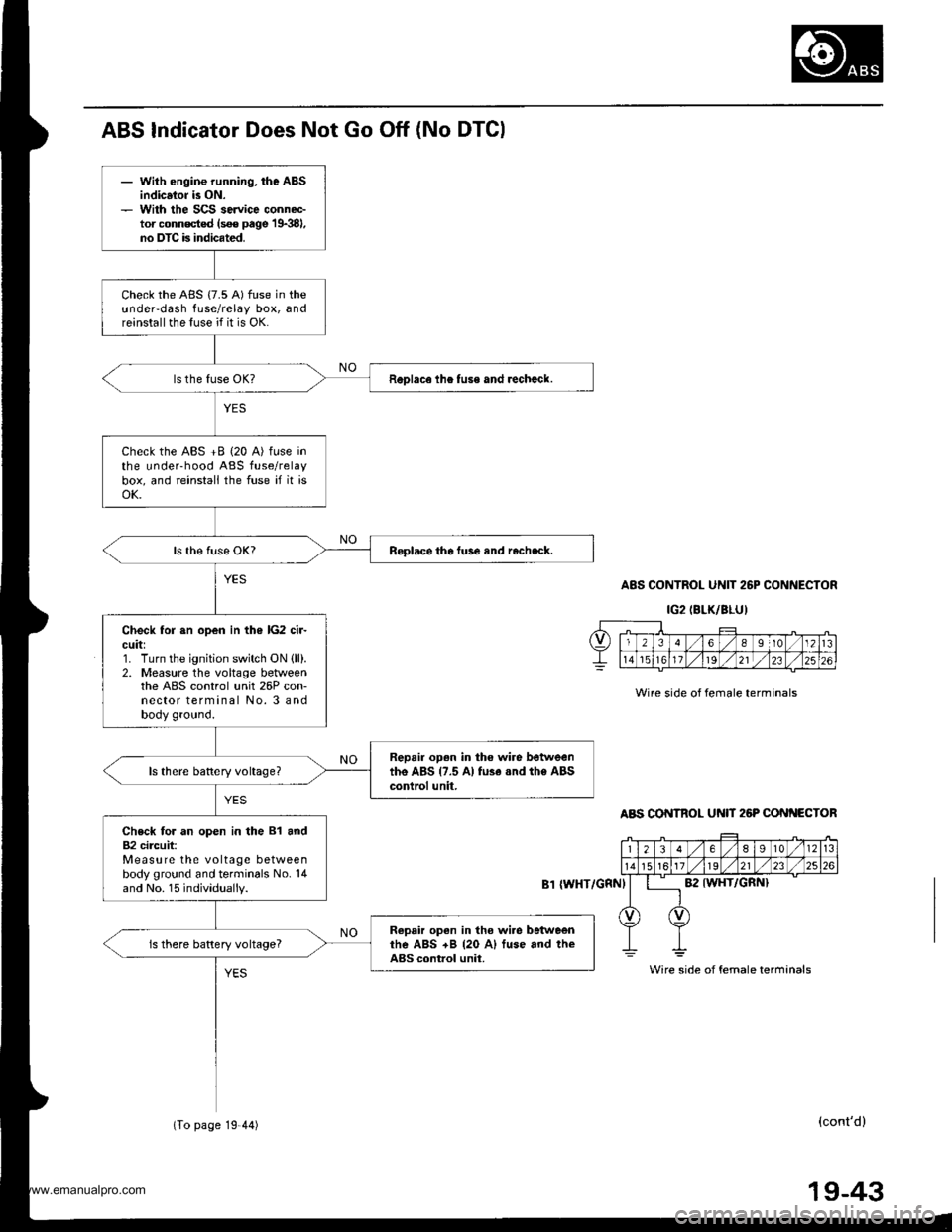
- With engine running, the ABSindicsior is ON.- With the SCS service connec-tor conn€cted (s€€ page 19381,no DTC is indicated.
Check the ABS {7.5 A) fuse in theundeFdash fuse/relay box, andreinstall the fuse if it is OK.
ReDlace lhe tuse and recheck.
Check the ABS +B (20 A) fuse inthe underhood ABS fuse/relaybox, and reinstall the fuse if it isoK.
Replace the fuse and rocheck.
Check for sn open in the lG2 cir-cuit:1. Turn the ignition switch ON {ll).2. Measure the voltage betweenthe ABS control unit 26P con-nector terminal No. 3 andbody ground.
Repair open in tho wire betweenthe ABS {7.5 A} fu3e .nd the ABScontrol unit,
Check for an open in the 81 and82 circuit:Measure the voltage betweenbody ground and terminals No. 14and No. 15 individually.
Ropair open in tho wi.e betweenrhe ABS +B {20 A) fuse and theABS control unit.is there battery voltage?
ABS Indicator Does Not Go Off (No DTGI
A8S CONTROL UNIT 26P CONNECTOR
IG2IBLK/BLU)
Wire side of female terminals
ABS CONTROL U N 26P CONf{ECTOR
{WHT/GRNI
(cont'd)
Wire side of female terminals
(To page 19 44)
19-43
www.emanualpro.com
Page 972 of 1395

DTC 51 - 53: ABS Pump Motor
NOTE: Short the PMR terminal to bodyground for a moment, and rochock the tuse.lf the fuse is blown, check lor a shon to bodyground in the MCK circuit.
NOTE: Short the PMR terminal to bodyground for a moment, and recheck the fuse,lf the tuse is blown, check tor a short to bodyground in the wire between the under hoodABS fuse/relay box 6nd the pump motor.
ABS CONTROL UNIT 22P CONNECTOR
Wire side of female terminals
(cont'di
- Wilh the ignition switch ON{ll), the ABS indicator doesnot go ott.- With the SCS seruico connec-tor connoctod {sce page 19381,DTCa 51 - 53 .re indicated.
check the MTR cHEcK (7.5 Ailuse in the under-hood ABStuse/relay box, and reinstall theluse if it is OK.
Rsplace the fuse and rech6ck.
check the PUMP MOTOR (40 A)fuse in the under-hood ABS fuse/relay box, and reinstall the fuse ifit is oK.
Roolace lhe tusg and rocheck.
Feplace the pump motor r6ley.
Check the pump motor powelsourc€ circuit:Turn the ignition switch ON (ll).
Ch6ck fo. a short to oowd in th6pump motor power sourca circuit:Remove the pump motor relay.Does the pump motor operate?
Repair rhort to power in the wirebclweon the under-hood ABSfuse/.6lay box and ihe ABSpump motor.
Does the pump motor operateT
Ch6ck tor loos6 ABS control unitconnectors. lf necotsary, 3ubsti-tute . known-good ABS controlunit and rocheck.
(To page 19 50)
19-49
www.emanualpro.com
Page 973 of 1395

Troubleshooting
DTC 51 - 53: ABS Pump Motor (cont'dl
(From page 19 49)
UND€R-HOOO ABSFUSE/REI-AY BOX
MOTOR +B IREDIMOTOR GND IBLKI
TERMINAL TERMINAL
PUMP MOTOR CONNECTOB
Fr MOTOR +B {WHTI12 lF-(v)vI
Terminal side of female terminals
Terminalside ofmaleterminals
ABS CONTROL UNIT 22P CONNECTOR
JUMPER WIRE
Wire side of female terminals
Chock the pump motor ci.cuit:1. Remove the pump motor relay.2. Turn the ignition switch ON {ll).3. Connect the pump motor relayconnector +B and MOTOR ter-minals with a jumpor wire fora moment,
Check for an open in the pump
motor +B circuit:1. Turn the ignition switch OFF.2. Disconnect the pump motor
3. Turn the ignition switch ON (ll).
4. Connect the pump motor relayconnector +B and MOTOR terminals with a iumper wire.5. Measure the voltage beaveenthe pump motor connectorterminal No. l and bodygrou nd.
Does the pump motor operate?
Bepair opon in the wire botweenthe under-hood ABS fuse/relavbor and the pump motor.ls there battery voltage?
Check the pump motor opera-tion:Connect the battery (+)terminal tothe pump motor connector termi-nal No. 1, and the (-) terminal tothe terminal No. 2 for a moment.
Reolace the modulator unit.
lFaulty pump moto.lDoes the pump motor operate?
Ch6ck for a short to body groundin the PMR circuit:1. Turn the ignition switch OFF.2. Disconnect the ABS controlunit 22P connector.3. Check tor continuity betweenterminal No. 19 and bodyground.
Repair open in the wire bstweenthe pump motor and body ground,
or poo. ground {G3511.
Repair short to body ground inthe wir6 botween the under-hood ABS tuse/rclay box and th€ABS contlol unit.
{To page 19-51)
www.emanualpro.com
Page 974 of 1395

(From page 19-50)
Chcck for .n opsn in the PCOMcircuit:1. Turn the ignition switch OFF.2. Reconnect the ABS controlunit 22P connector.3. Connect the SCS service con-nector.4. Turn the ignition switch ON {ll).5. Measure the voltage betweenthe pump motor relay con-nector PCOM terminal andbody ground.
Repair opon in the wire betwoenthe under-hood ABS fuse/relaybox and tho ABS conlrol unh.ls there approx.3 V?
Check for an open in tho PMR cir-cuh:Measure the voltage between theABS control unit 22P connectorterminal No. 19 and body ground.
Ropair open in tho wir6 botwagntho undcr-hood ABS fuse/rolaybox .nd the ABS control unit.ls there approx. 3 V?
Ch.ck tor an opon in the MCKci.cuit:1. Turn the ignition switch OFF.2. Disconnect the SCS serviceconnector.3. Turn the ignition switch ON (ll).
4. Measure the voltage betweenthe ABS control unit 22P connector terminal No. 17 andbody ground while connect-ing the pump motor relayconnector +B and MOTOR ter-minal with a jumper wire tormoment,
Repair open in the wiro bdtweenthe under-hood ABS fus6/telaybox .nd the ABS control unit.ls there battery voltage?
Chock for loose ABS control unitconnectoas, It necsssary, substi-tule a known-good ABS controlunit and aocheck.
tr) l--l
r"r
ABS CONTROL UNIT 22P CO NECTOR
Wire side of female terminals
1t011
MCK IBRN,/YEL}
www.emanualpro.com
Page 975 of 1395
![HONDA CR-V 2000 RD1-RD3 / 1.G Workshop Manual
Troubleshooting
DTG 54: Main Relay
IWHT/GRNI
AAS CONTROL UNIT 26P CONNECTON
Wire side of female terminals
ABS COf{TROL UN]T 22P CONNECTOR
PCOMIGRN/WHTIscoM{BLK/WHTI
Wire side of female terminals
- Wi HONDA CR-V 2000 RD1-RD3 / 1.G Workshop Manual
Troubleshooting
DTG 54: Main Relay
IWHT/GRNI
AAS CONTROL UNIT 26P CONNECTON
Wire side of female terminals
ABS COf{TROL UN]T 22P CONNECTOR
PCOMIGRN/WHTIscoM{BLK/WHTI
Wire side of female terminals
- Wi](/manual-img/13/5778/w960_5778-974.png)
Troubleshooting
DTG 54: Main Relay
IWHT/GRNI
AAS CONTROL UNIT 26P CONNECTON
Wire side of female terminals
ABS COf{TROL UN]T 22P CONNECTOR
PCOMIGRN/WHTIscoM{BLK/WHTI
Wire side of female terminals
- With the ignition switch ON(lll, the ABS indicator doesnot go off.- With the SCS service connec-tor connected {see page 19-381,DTC 54 is indicatod.
Check the ABS +B 120 A) fuse inthe under-hood ABS luse/relaybox, and reinstall the fuse if it isoK.
FeDlace the tu3e and recheck.
Ch€ck tor an open in the 81, 82circuit:Measure the voltage betweenbody ground and the ABS controlunit 26P connector terminal No. 14and No. 15 individually.
Repair open in the wiro bstweonth6 ABS conirol unit and theunder-hood ABS fuse/rolay box,
ls there battery voltage?
Check for a short to body groundin the PMR circuit:L Turn the ignition switch OFF.2. Remove the pump motor relay.3. Disconnect the ABS controlunit 22P connector.4. Check lor continuity betweenterminal No. 19 and bodygrouno.
Repair short to body ground inthe wire betweon the under-hood ABS lGe/r.lay box and theABS control unit.
Check for a short to body groundin the PCOM, SCOM cilcuit:1. Disconnect the ABS controlunit 26P connector.2. Check tor continuity betweenbody ground and the ABS con-trol unit 26P terminals No- 1and No.2 individually.
. R€pair short to body ground inth€ P1COM circuit wire betweenthe ABS control unit and theund6r-hood ABS tuse/r6layoox.. R6p.ir short to body ground inthe PCOM or SCOM circuit wirebetweon th6 ABS control unitand lhe mod!lator unit.. R.Dlece tho modulrtor unit.(Short circuit inside the unitl
ls there continuity?
(To page 19-53)
www.emanualpro.com
Page 1034 of 1395

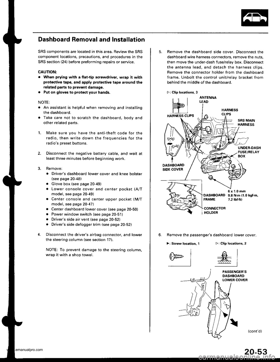
Dashboard Removal and Installation
SRS components are located in this area. Review the SRS
component locations, precautions, and procedures in the
SRS section {24) before preforming repairs or service.
CAUTION:
. When prying with a flat-tip screwdriver, wrap h withprotective tap€, and apply protective tape around the
related parts to prevgnt damage.
. Put on gloves to prot€ct your hands.
NOTE:
. An assistant is helpful when removing and installing
the dashboard.
. Take care not to scratch the dashboard, bodv and
other related parts.
1.Make sure you have the anti-theft code for the
radio, then write down the frequencies for the
radio's preset buttons.
Disconnect the negative battery cable. and wait at
least three minutes before beginning work.
Removei
a Driver's dashboard lower cover and knee bolster(see page 20-48)
. Glove box (see page 20-49)
. Lower console cover and center pocket (A/T
model, see page 20-49)
. Center console and center upper pocket (M/T
model, see page 20-47)
. Center dashboard lower cover (see page 20-50)
. Power window switch (see page 20-51)
. Driver's side air vent (see page 20-52)
. Driver's side defogger trim (see page 20-52)
Disconnect the driver's airbag connector, and lower
the steering column (see section 17)
NOTE: To prevent damage to the steering column,
wrap it with a shop towel.
2.
5. Remove the dashboard side cover. Disconnect the
dashboard wire harness connectors, remove the nuts,
then move the under-dash fuse/relay box. Disconnect
the antenna lead, and detach the harness clips.
Remove the connector holder from the dashboard
frame. Unbolt the control unit/relay bracket from
behind the middle of the dashboard.
HARNESS
6. Remove the passenger's dashboard lower cover.
D: Clip locations,
nl
-$t- Issj
I
ANTENNALEAD
>: Clip locations.
rttl
slllll
>: Scr€w location, 1
I
SF:oo I-l
SRS MAINHARNESS
UNDER.DASHFUSE/RELAYBOX
OASHBOARDSIDE COVER
6x1.0mm9.8Nm11.0kgf.m,7.2tbt.ftlDASHBOARDFFAME
CONNECTORHOLDER
PASSENGER'SDASHBOARDLOWER COVER
{cont'd)
www.emanualpro.com
Page 1095 of 1395
SLOWER MOTOR RELAY,RADIATOR FAN RELAY.CONDENSER FAN REI-AY,COMPRESSOR CLUTCH RELAY(Located in the undeFhood fuse/relay box)Test. page 22-45
CONDENSER FAN 2P CONNECTOB
RADIATOR FAN2P CONNECTORA/C PRESSURE SWITCH2P CONNECTOR
COMPARTMENTWIRE HARNESS
{cont'd)
1P CONNECTOR
22-5
www.emanualpro.com