Page 1281 of 1395
Hatch Glass Opener
Circuit Diagram
BATTEFY
@*"
UNDER.H@D FUSE/RELAY BOX
|-*;rr^!...',r,*;l.......1<\o<
+l
I
I
IWHT/GRN
WHT/GRN
II
rt
KEYLESSiPOWEF DOOB LOCKCONTROL UNIT
V
IIIYEL
HATCHGLASSOPENERsoLENOr0
J
TBLK
I
out,G631
WHT/GBN
Ot-
23-121
1. Remove the dashboard lower cover (see section
20).
2. Disconnect the 2P connector from the switch.
3. Remove the switch from the dashboard lower
cover.
Switch Test
DASHBOANDLOWER COVER
HATCH GLASSOPENER SWITCH
Check for continuity between the No. 1 and No. 2
terminals.
. There should be continuity when the switch is
pushed.
. There should be no continuity when the switch is
released.
www.emanualpro.com
Page 1313 of 1395
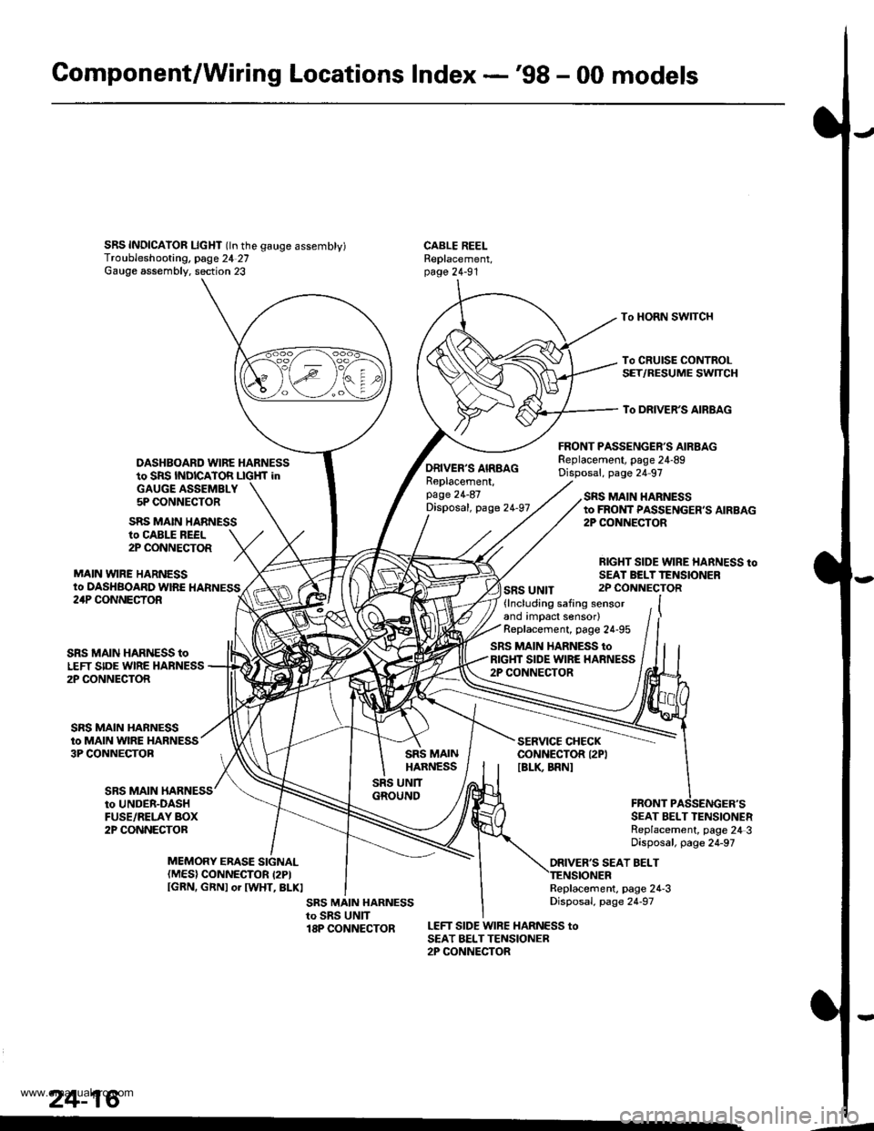
Gomponent/Wiring Locations Index -'98 - 00 models
SRS INDICAIOR LIcHT (ln the gauge assembty)Troubleshooting, page 24 27Gauge assembly. section 23
DASHBOARD WIRE HARNESSto SRS INDICATOR LIGHf inGAUGE ASSEMBLY5P CONNECTOR
FRONT PASSENGER'S AIRBAGReplacement, page 24-89Disposal, page 24 97
CABLE REELReplacement,page 24-91
To HORN SWITCH
To CRUISE CONTROLSET/RESUME SWTCH
To DRIVER'S AIRBAG
ro CABLE REEL2P CONNECTOR
MAIN VYIRE HARNESSto DASHBOARD WIRE HARNESS
SRS MAIN HARNESS
ORIVER'S AIRBAGReplacement,page 24-87Disposal, page 24-97
SRS UNIT
SRS MAIN HARNESSto FROI{T PASSENGER,S AIRBAG2P CONiIECTOR
RIGHT SIDE WIRE HARNESS toSEAI BELTTENSIONER2P CONNECTOR24P CONNECTOR
SRS MAIN
SRS MAIN HARNESS toLEFT SIDE WIRE HARNESS2P CONNECTOR
SRS MAIN HARNESSto MAIN WIRE HARNESS3P CONNECTOB
(lncluding safing sensorand impact sensor)Replacement, page 24-95
SRS MAIN HARNESS toRIGHT SIDE WIRE HARNESS2P CONNECTOR
SERVICE CHECKCONNECTOR I2PIIBLK BRNI
to UNDER-DASHFUSE/RELAY BOX2P CONNECTORSEAT BELT TENSIONERReplacement, page 24 3Disposal, page 24-97
ORIVER'S SEAT BELTMEMORY ERASE SIGNAL(MES) CONNECTOR I2PIIGRN, GRNI or IWHT, BLKIReplacement, page 24-3Disposal, page 24-97
LEFT SIDE WIRE HARNESS toSEAT BELTTENSIONER2P CONNECTOR
24-16
.4
www.emanualpro.com
Page 1317 of 1395
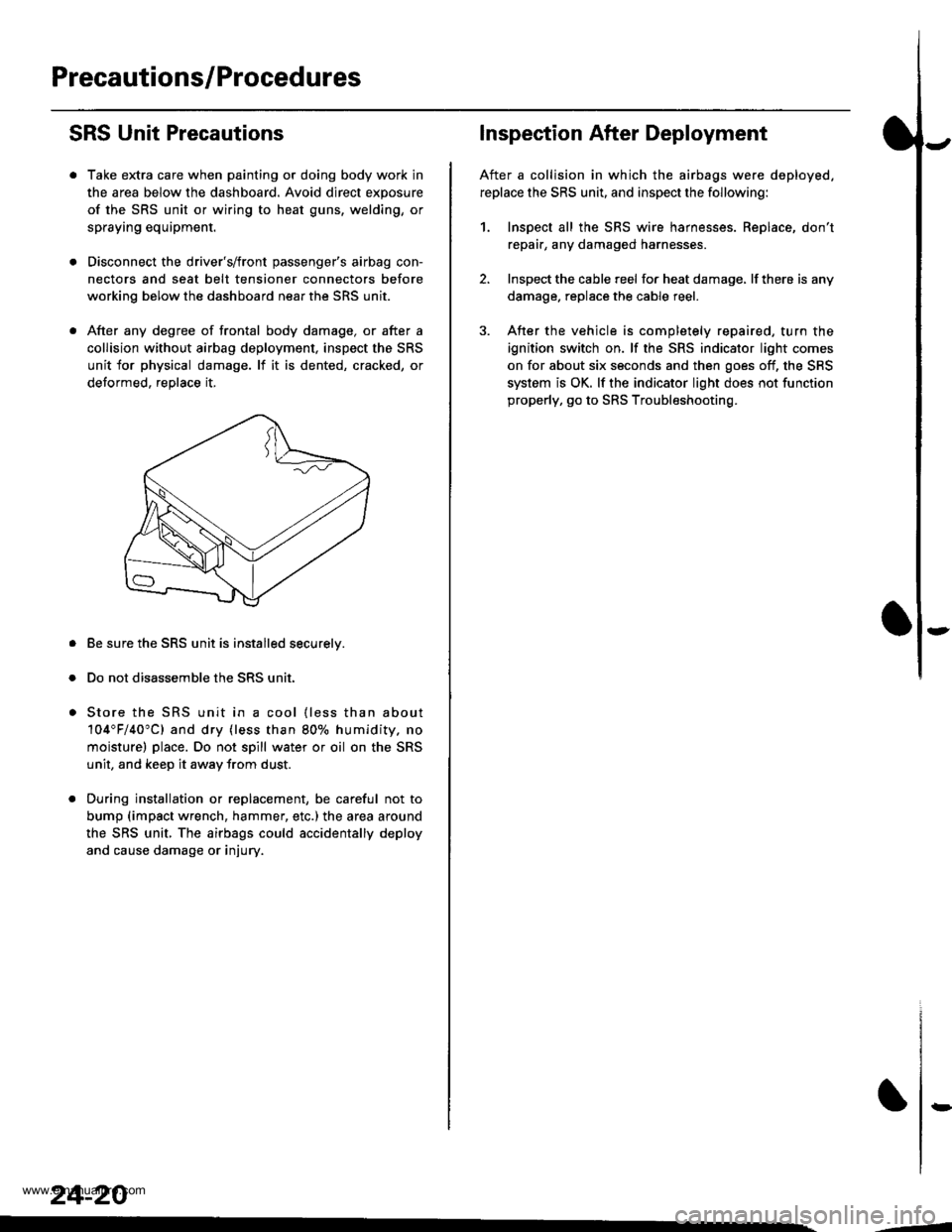
Precautions/Procedures
SRS Unit Precautions
Take extra care when painting or doing body work in
the area below the dashboard. Avoid direct exposure
of the SRS unit or wiring to heat guns, welding, or
spraying equipment.
Disconnect the driver's/front passenger's airbag con-
nectors and seat belt tensioner connectors before
working below the dashboard near the SRS unit.
After any degree of frontal body damage, or after a
collision without airbag deployment, inspect the SRS
unit for physical damage. lf it is dented, cracked, or
detormed, reolace it,
Be sure the SRS unit is installed securelv.
Do not disassemble the SRS unit.
Store the SRS unit in a cool {less than about
104"F/40"C) and dry {less than 80o/o humidity. no
moisture) place. Do not spill water or oil on the SRS
unit, and keep it awav from dust.
During installation or replacement, be careful not to
bump (impact wrench, hammer, etc.) the area a[ound
the SRS unit, The airbags could accidentally deploy
and cause damage or injury.
24-20
,..4
Inspection After Deployment
After a collision in which the airbags were deployed.
replace the SRS unit, and inspect the following:
1. Inspect all the SRS wire harnesses. Replace, don't
repair, any damaged harnesses
2. Inspect the cable reel for heat damage, lf there is any
damage. replace the cable reel.
3. After the vehicle is completely repaired, turn the
ignition switch on. lf the SRS indicator light comes
on for about six seconds and then goes off, the SRS
system is OK. lf the indicator light does not function
properly, go to SRS Troubleshooting.
rD
www.emanualpro.com
Page 1320 of 1395
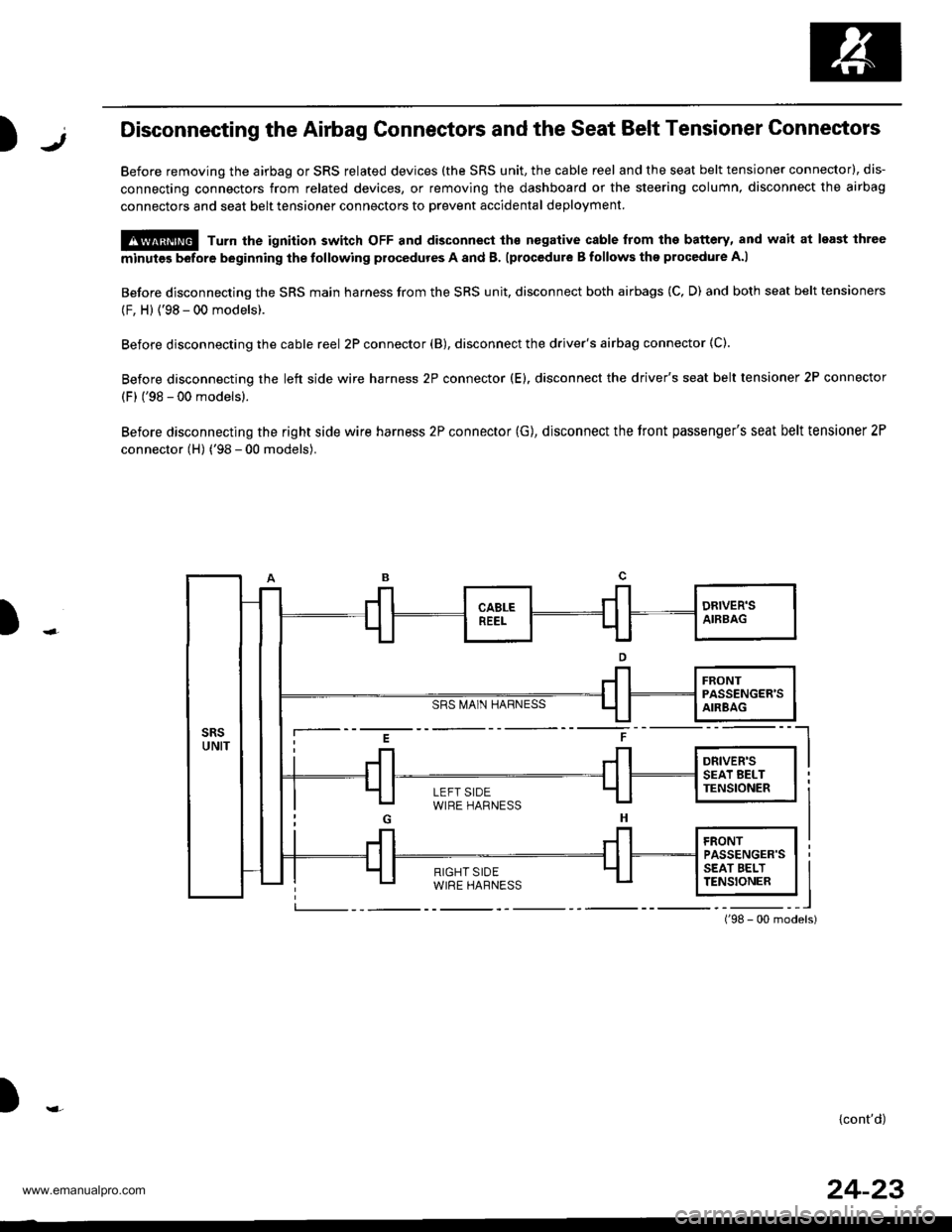
)1,Disconnecting the Airbag Gonnectors and the Seat Belt Tensioner Connectors
Before removing the airbag or SRS related devices (the SRS unit, the cable reel and the seat belt tensioner connector), dis-
connecting connectors from related devices, or removing the dashboard or the steering column, disconnect the airbag
connectors and seat belt tensioner connectors to Drevent accidental deployment
@ Turn the ignition switch oFF and disconnect ths nogative cable from the battery, and wait at least ihree
minutes before beginning the tollowing procedures A and B. lprocedure B follows the procedure A.l
Before disconnecting the SRS main harness from the SRS unit, disconnect both airbags (C, D) and both seat belt tensioners
(F, H) {'98 - 00 models).
Before disconnecting the cable reel 2P connector (B), disconnect the driver's airbag connector (C).
Before disconnecting the left side wire harness 2P connector (E). disconnect the driver's seat belt tensioner 2P connector
(F) ('98 - 00 models).
Before disconnecting the right side wire harness 2P connector (G), disconnect the tront passenger's seat belt tensioner 2P
connector (H) ('98 - 00 models).
SRS MA1N HARNESS
)
i--- E t ----l
i Jl Jl l*",r* I I
LEFT SIDEWIRE HARNESS
){cont'd)
24-23
www.emanualpro.com
Page 1330 of 1395
SRS Indicator Light Wire Connections
SRS Indicator Light Power Circuit
DASHBOARD WIRE HARNESS
YEL
BLK
To UNDER-DASHFUSE/RELAY BOX <_
20P CONNECTOR
To GAUGEcsog + assEMBLy
SRS Indicator Light Control Circuit
SRS MAIN HARNESS
)-MAIN WIRE HARNESS
VAIVBIt
To UNDER-DASHFUSE/BELAY BOX2P CONNECTOR
c414MAIN WIRE HARNESS 3P CONNECTORTerminal side of msle t€rminals
c415MAIN wlRE HARNESS 24P CONNECTORTerminal aide of male terminals
c502DASHBOARD WIRE HARNESS 2OP CONNECTORWire side of lemslo terminsls
c503OASHBOARD WIRE HARNESS 24P CONNECTORWire side of female t€rminal3
c509DASHBOABD WIRE HARNESS 5P CONNECTORWire sid€ ot lemale te.minals
c801SRS MAIN HARNESS 2P CONNECTORwire side ol f.male terminals
c803SRS MAIN HARNESS 3P CONNECTORWire side ol female terminals
c806SRS MAIN HARNESS T8P CONNECTORWire side of lomrle terminals
)
24-33
www.emanualpro.com
Page 1332 of 1395
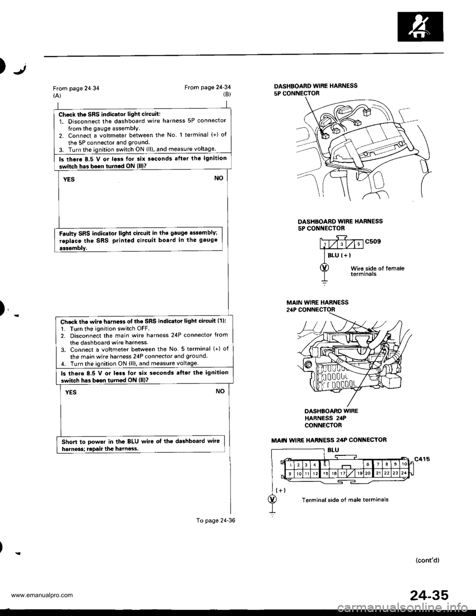
Chock th6 SRS indic.lor light circuit:1. Disconnect the dashboard wire harness 5P connector
from the gauge assembly.2. Connect a voltmeter between the No l terminal (+) o{
the 5P connector and grouncl.
3. Turn the ignition switch ON {ll), and measure voltage
ls thero 8.5 V or lats for 3ix second! aflsr the ignition
switch ha3 bo€n turnod ON (ll)7
YESNO
Fdulty SRS indicator light cilctlit in ths gauge sssomblY;
replaco tho SRS printod circuit board in the gauge
aasombly,
Chock th6 wire harn.$ of the SRS indicstor light circuh (11:
1. Turn the ignition switch OFF.2. Disconnect the main wire harness 24P connector from
the dashboard wire harness-3. Connect a voltmeter between the No 5 terminal (+) of
the ma;n wire harness 24P connecior and ground
4. Turn the ignition ON {ll), and measure voltage.
ls there 8,5 V or l€r3 tor six s€cond3 efter the ignilion
switch has bssn turnod ON llll?
YESNO
Short to powor in the BLU wire of tho dashbosrd wire
harne3s; Epait the harne3.s.
To page 24-36
Jt)
From page 24 34(A)From page 24-34(8)DASHBOARD WIRE HARNESS
5P CONNECTOR
DASHBOARD WIRE HARI{ESS5P CONI{ECTOR
c509
Wire side ol femaleterminals
)_
DASHBOARO WIREHARNESS 24PCONNECfOR
(cont'd)
MAIN WIRE HARNESS
MAIN WIRE HARI{ESS 2/tP COI{ ECTOR
Terminal side of male terminals
24-35
www.emanualpro.com
Page 1335 of 1395
Troubleshooting
The SRS Indicator Light Doesn't Go Off - '97 model (cont,d)
From page 24 37(A)
SRS MAIN HARNESS 18P CONNECTOR
(B)To page 24'39
DASHBOARD WIRE HARNESS5P CONNECTOR
(c)To page 24-40
DASHBOAND WIRE HARI{ESS5P CONNECTOR
)
J
c509
Wire side ol femaleterminals
T
Check the SRS unit:Connect the SRS main harness 18P connector terminals No.6 and No.7 with a jumper wire and backprobe
Faulty SRS unit or poo. contact at the SRS main ha.ness18P connectoi; check the connector.lfthe conneqtor is OK, replace the SRS unit.
Oid tuse No. 13 (15 Al blow?
Check for a short to ground in the SRS indicator tight cir-cutl:1. Turn the ignitlon switch oFF.2, Disconnect the dashboard wire harness 5p connectorfrom the gauge assembly.3. Check resistance between the No. 1 terminal ofthe dashboard wire harness 5P connector and ground. Thereshould be 1 MO or more.
Shon to ground in th6 gaugo assembly; replaco the gau96
JUMPER WIRE
Wlre sido ot tomale terminsls
243a
--
www.emanualpro.com
Page 1336 of 1395
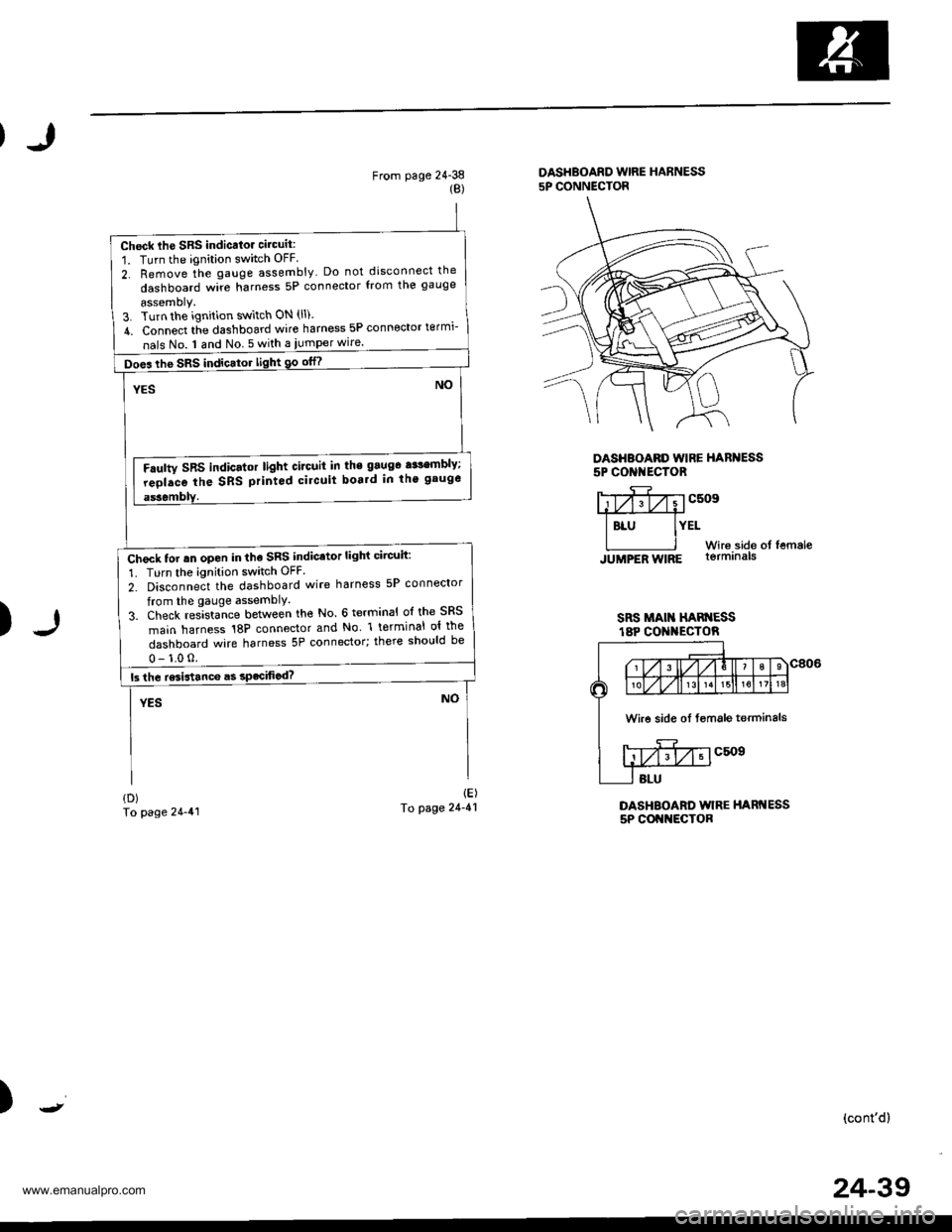
Check lhe SRS indicalor circuit:
1. Turn the ignition switch OFF
2. Remove the gauge assembly Do not disconnect the
dashboard wire harness 5P connector from the gauge
assemoly.3. Turn the ignition switch ON (ll).
4. Connect tie dashboard wire harness 5P connector termi-
nals No. I and No 5 with a iumper wire.
Does the SRS indicator light 90 otn
Faulty SRS indicator light circuit in the 9aug6 a$embly;
reolace the SRS printod circuit boa.d in th' gauge
Check tor rn open in the SRS indicator light circuit:
1. Turn the ignition switch OFF
2. Disconnect the dashboard wire harness 5P connector
from the gauge assemblY.
3. Check res]sta-nce between the No. 6 terminal ol the SRS
main harness 18P connector and No l terminal ol the
dashboard wire harness 5P connector; there should be
From page 24-38{B)
DASHBOARD WIRE HARNESS5P CONNECTOR
DASHBOARD WIRE HARNESS5P CONI{ECTOR
)
Y;yfivvcsosffi
I BLU IYELWir6.side of femaleJUMPER WIRE lormrna|s
SRS MAI HAN ESSt8P CO I{ECTOR
DASHBOARD WIRE HARNESS5P COI{NECTOR
{D)To page 24-41
1E)To page 24-41
)(cont'd)
Wire side oI fsmale terminals
24-39
www.emanualpro.com