Page 1105 of 1395
From page 22-14
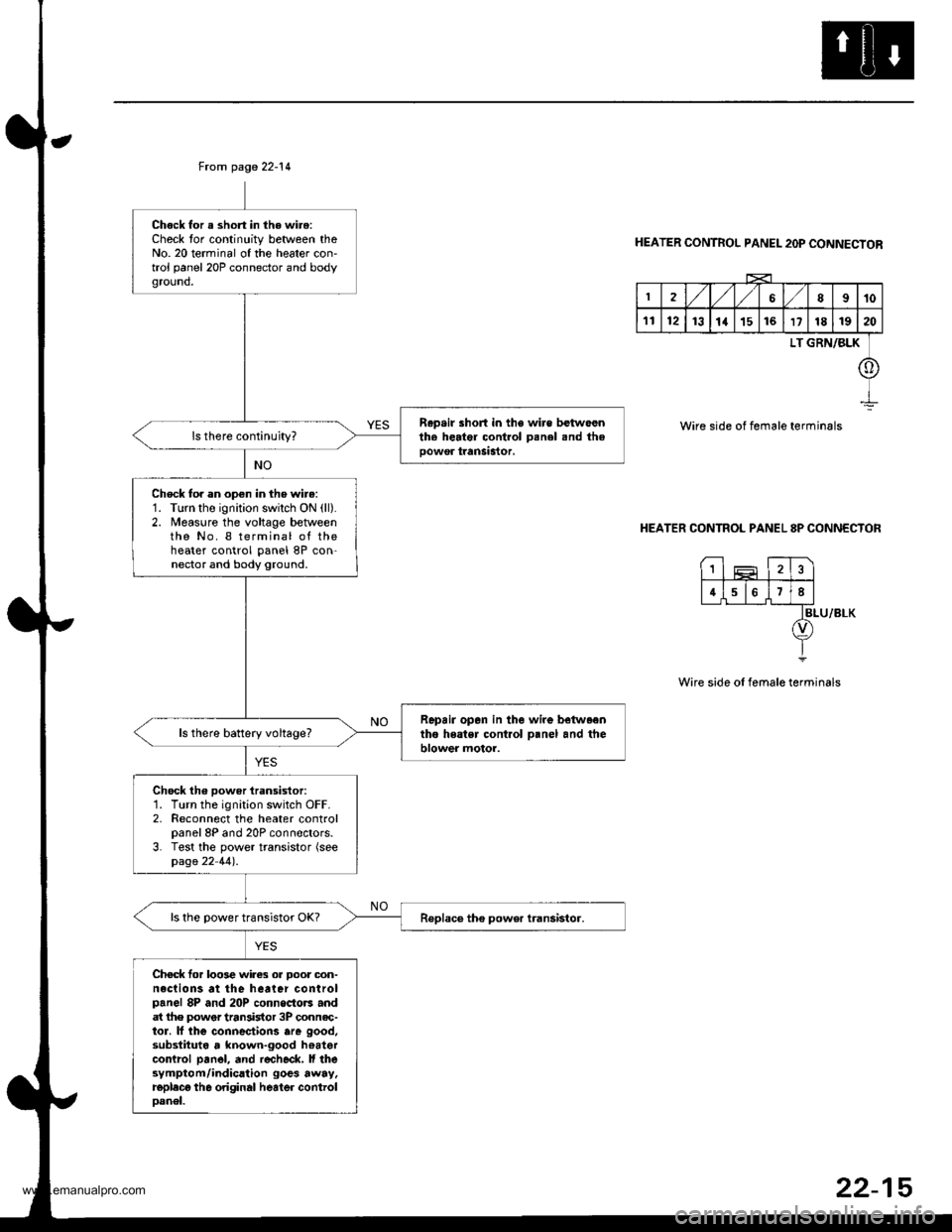
Chock for a short in the wire:Check tor continuity between theNo. 20 terminal of the heater con'trol panel 20P connector and bodyground,
R.p.ir short in the wire betwoenth. herter control Denel snd theoowor tranSastor.
Check to. an open in the wire:1. Turn the ignition swilch ON (ll).
2. Measure the voltage betweenthe No. I terminal of theheater control panel 8P con-nector and body ground.
Repair opan in the wire betwaentho heatsr cont.ol o.nel and theblower motor.ls there battery voltage?
Chock th6 power iransistor:1. Turn the ignition switch OFF.2. Reconnect the heater controlpanel 8P and 20P connectors.3. Test the power transistor (seepage 22 44).
ls the power transistor OK?
Chec* for loo3e wires or Door oon-neclions at the heater controlpanel 8P and 20P connoctors andat lhe power tran3istor 3P connec-tor. lf lhe connectiorc are good,substituta , known-good hoatercontrcl pan6l, and r€check. ll thesymptom/indication goes away.replecg th6 original heater controloanel.
HEATER CONTROL PANEL 2OP CONNECTOR
2,/1,/l/68910
1112131a151617181920
LT GRN/BLK
o
Wire side of female terminals
HEATER CONTROL PANEL 8P CONNECTOR
BLU/8LK
Wire side of female terminals
1
4678
22-15
www.emanualpro.com
Page 1112 of 1395
Troubleshooting
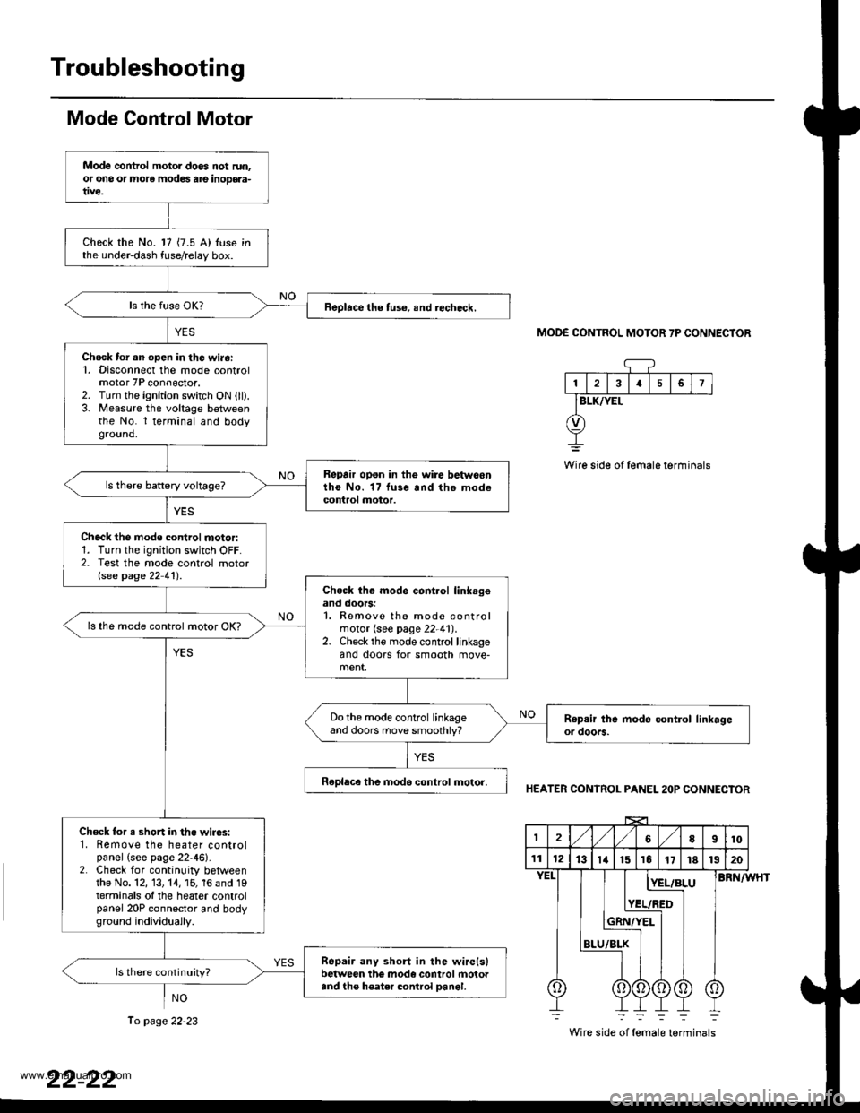
Mode Control Motor
NO
MODE CONTROL MOTOR 7P CONNECTOR
13I5
BLK/YEL
Wire side of female terminals
HEATER CONTROL PANEL 2OP CONNECTOR
BRN/WHT
Wire side of female terminals
Mode control motol does not run.or ono or more modes are inoD€aa-
Check the No. 17 {7.5 A) Iuse inthe under-dash fuse/relay box.
Replace the tus€, snd iecheck.
Chock tor an open in th€ wi.6:1. Disconnect the mode controlmotor 7P connector.2. Turn the ignition switch ON (ll).3. Measure the voltage betweenthe No. l terminal and bodyground.
Repair opon in the wire betwoontho No. 17 luse and tho modecontrol motor.
Check the mode control motor:1. Turn the ignition switch OFF.2. Test the mode control motorGee page 22 41') .
Chock th€ mode cont.ol link.geand doors:1. Remove the mode controlmotor (see page 22-41).2. Check the mode control linkageand doors for smooth move-ment,
ls lhe mode control motor OK?
Do the mode control linkageand doors move smoothly?
Replece the inod6 control motor.
Chock for s shon in the wir€s:1. Remove the heater controlpanel (see page 22'46).2. Check for continuity betweenthe No. 12, 13, 14, 15, 16 and 19terminals ol the heater controlpanel 20P connector and bodyground individuaily.
Repair any short in the wire(slbetween the mode control rnotoaand the h6ater control Danel.
ls there continuity?
2l,/1,/8I10
111213ta151617r81320
BLU
[E!r!
YEL/RED
Ii
To page 22-23
www.emanualpro.com
Page 1114 of 1395
Troubleshooting
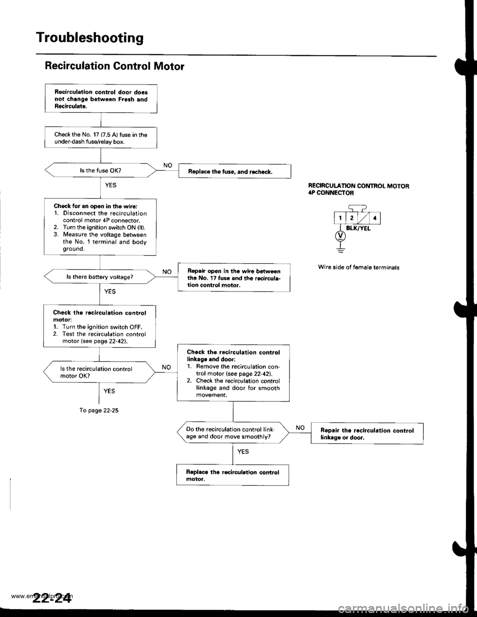
Recirculation Gontrol Motor
YES
To page 22-25
REORCULATION CONTROL MOTOR,rP CONNESTOR
q?- T--- V-l
l1, lrl/l1lI BI.IUYEL(v)
+
Wire side of female terminals
Rocirculation control door do6snoi chango botw€en Fresh andReci.culate.
Check the No. 17 {7.5 A)tuse in theunder-dash f use/relay box.
Roplace the fu36, and rechock.
Check for .n open in the wire:1. Disconnect the recirculationcontrol motor 4P connector.2. Turn the ignition switch ON (ll).3. Measure the voltage betlveenthe No. l terminal and bodyground.
Repair op6n in the wire bdtweenthe No. 17 fuse and thc recircule-tion control motor.
Check the rocirculation controlmoior:1. Turn the ignition switch OFF.2. Test the recirculation controlmotor (see page 22-42).
Chock ths r.circulation controllinkag. end doori1. Remove the recirculation con-trol motor (see page 22,42).2. Check the recirculation controllinkage and door for smooth
Do the recirculation control linkage and door move smoothly?Boprir the recirculrtion controllinkag. or dooJ,
www.emanualpro.com
Page 1126 of 1395
Troubleshooting
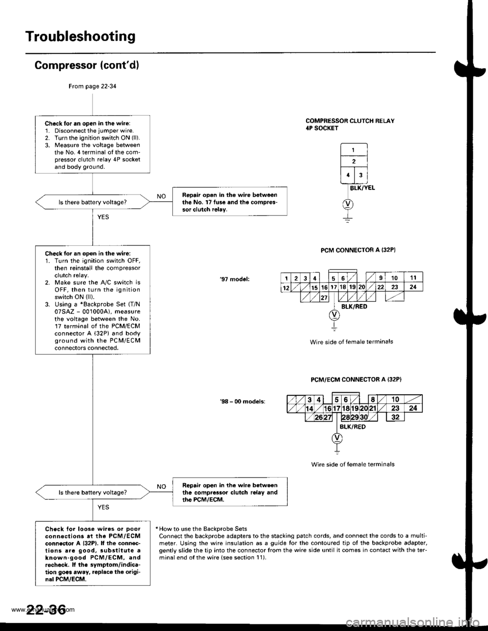
Compressor (cont'dl
COMPRESSOR CLUTCH RELAY4P SOCKET
1
2
43
BLK/YEL
PCM CONNECTOB A I32P)
'97 model:
Wire side of female terminals
PCM/ECM CONNECTOR A {32P}
38 - 00 models:
Wire side of {em6le terminals
* How to use the BackDrobe SetsConnect the backprobe adapters to the stacking patch cords, and connect the cords to a multi-meter. Using the wire insulation as a guide for the contoured tip ot the backprobe adapter,gently slide the tip into the connector trom the wire side until it comes in contact with the teFminalend o{the wire {see section l1).
Frcm page 22-34
Ch6ck for an open in the wire:1. Disconnect the jumper wire.2. Turn the ignition switch ON (ll).
3, Measure the voltage betweenthe No. 4 terminal ot the com'pressor clutch relay 4P socketand body ground.
Repair op.n in the wire betweenthe No. l7 fu3e and the compres-sor clutch ielay.
Check for an opon in the wire:1. Turn the ignition switch OFF,then reinstall the compressorclutch relay.2. Make sure the A"/C switch isOFF, then turn the ignitionswitch ON (ll).
3. Using a *Backprobe Set (T/N
07SAZ - 001000A), measurethe voltage between the No.17 terminal ol the PCM/ECMconnector A (32P) and bodyground with the PC M/ECMconnectors connected,
Repair open in lhe wire betwoonthe compressor clutch r6lay andthe PCM/ECM.
Check tor loose wires or Doorconnections at the PCM,/ECMconnecto. A {32P1. lf the connec-tions are good, sub3titute aknown-good PCM/ECM, androcheck. lf the symptom/indica-tion goas away, replac€ the origi-nal PCM/ECM.
126I1011
12151617'181S222321
BLK/RED
22-36
www.emanualpro.com
Page 1127 of 1395
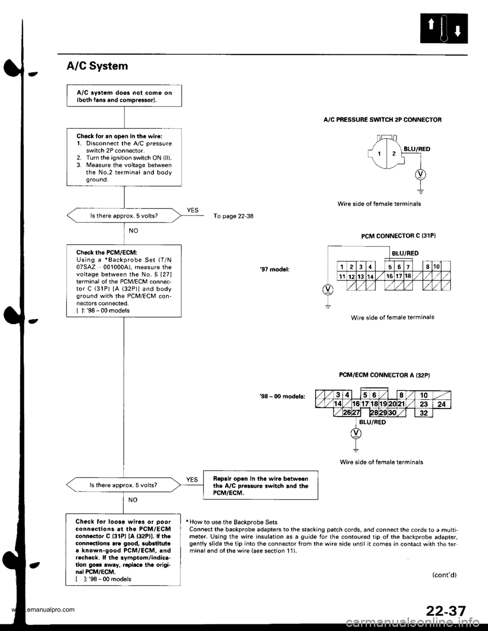
A/C aystem does not come on{both fans and comDrossor).
Ch6ck lor .n open in the wire:1. Disconnect the A,/C pressureswitch 2P connector.2. Turn the ignition switch ON (ll).
3. Measure the voltage betweenthe No.2 terminal and bodyground.
ls there approx. 5 volts?
check tho PcM/EcM:Using a *Backprobe Set (T/N
07SAZ 0010004). measure thevoltage between the No.5 t27lterminal of the PCM/ECM connec,tor C (31P) [A 132P)l and bodyground with the PCM/ECM con-nectors connected,I l: '98 - 00 models
Rop.ir open in th6 wire botweonthe A/C Dr*sure switch and thePCM/ECM.
ls there approx.5 volts?
Check tor loo3e wires or Doorconnections at the PCM/ECMconnoctor C l3lPl lA (32Pll. It theconnections arg good, 3ubdtitut€a known-good PCM/ECM, andrecheck. ll the 3ymptom/indica-tion go.. eway, r€placo thG origi-nal PCM/ECM,[ ]: '98 -00 models
A/C System
A/C PRESSURE SWITCH 2P CONNECTOR
fo page 22-38
PCM CONNECTOR C (31PI
'97 modol:
Wire side of female terminals
PCM/ECM CONNECTOR A I32P'
38 - 00 modeb:
Wire side of female terminals
* How to use the Backprobe SetsConnect the backprobe adapters to the stacking patch cords, and connect the cords to a multi-meter. Using the wire insulation as a guide for the contoured tip ol the backprobe adapter,gently slide the tip into the connector from the wire side until it comes in contact with the ter.minalond olthe wire (see section 11).
(cont'd)
22-37
www.emanualpro.com
Page 1131 of 1395
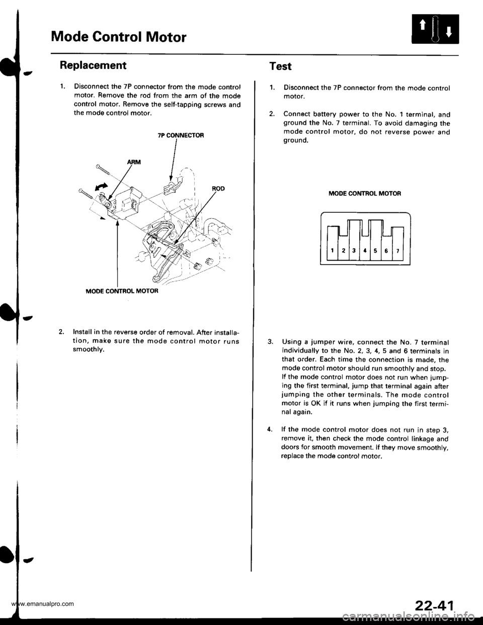
Mode Control Motor
Replacement
1. Disconnect the 7P connector from the mode control
motor. Remove the rod from the arm of the mode
control motor, Remove the self-tapping screws and
the mode control motor.
2.Install in the reveGe order of removal. After installa-
tion, make sure the mode control motor runssmoothlv.
7P CONNECTOR
MODE CONTROL MOTOR
Test
1.Disconnect the 7P connector from the mode control
motor.
Connect battery power to the No. 1 terminal, andground the No. 7 terminal. To avoid damaging the
mode control motor, do not reverse power andgrouno.
MODE CONTROL MOTOR
Using a jumper wire. connect the No. 7 terminalindividually to the No, 2,3, 4,5 and 6 terminals in
that order. Each time the connection is made. the
mode control motor should run smoothly and stop.
lf the mode control motor does not run when jump-
ing the first terminal, jump that terminal again afterjumping the other terminals. The mode control
motor is OK it it runs when jumping the first termi-
nal again.
lf the mode control motor does not run in step 3,remove it, then check the mode control linkage and
doors for smooth movement. lf they move smoothly,
reDlace the mode control motor.
www.emanualpro.com
Page 1132 of 1395
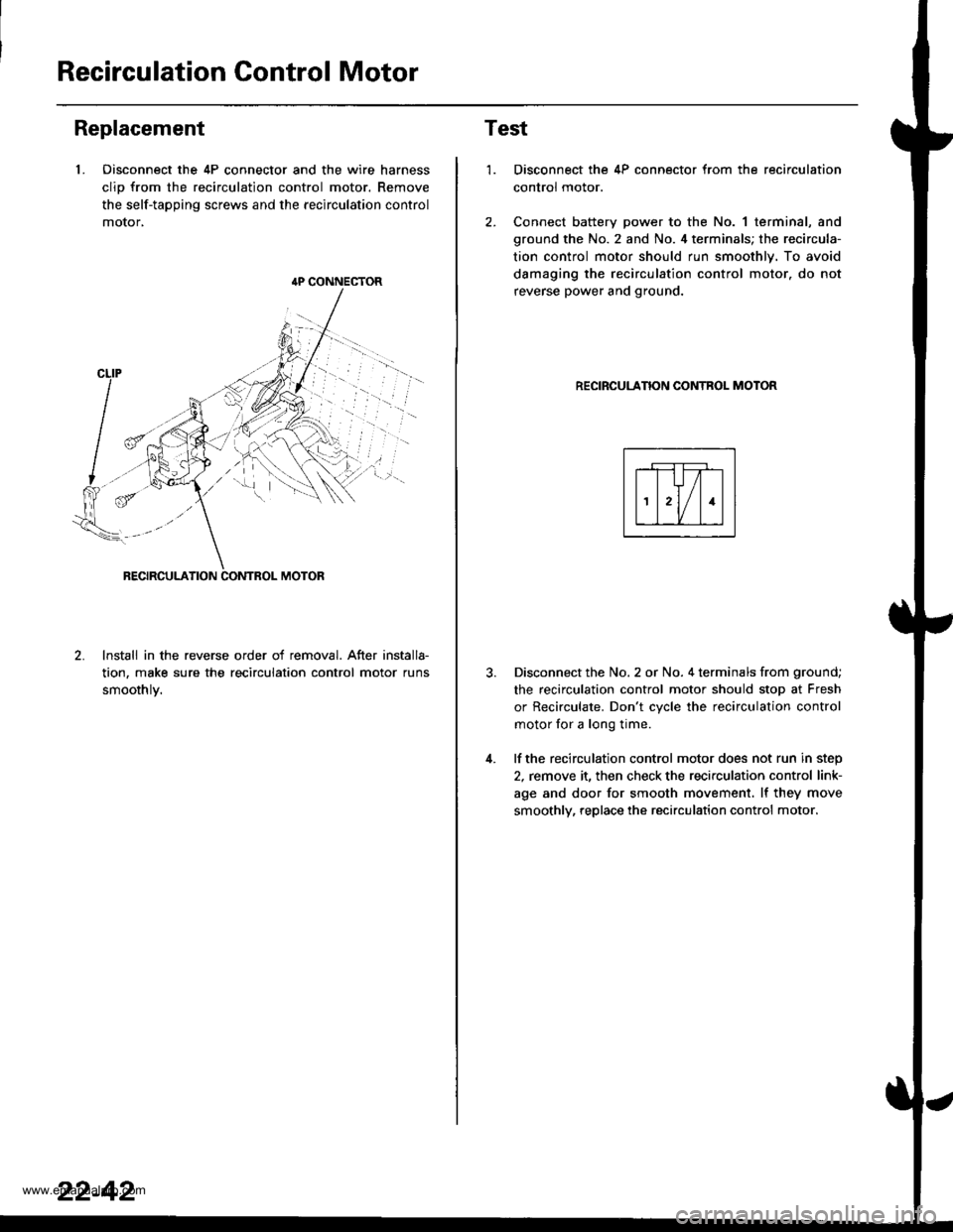
Recirculation Control Motor
Replacement
1. Oisconnect the 4P connector and the wire harness
clio from the recirculation control motor. Remove
the self-tapping screws and the recirculation control
motor,
lnstall in the reverse order of removal. After installa-
tion, make sure the recirculation control motor runs
smoothlv.
{P CONNECTOR
22-42
Test
1.
4.
Disconnect the 4P connector from the recirculation
control motor.
Connect battery power to the No. 1 terminal, and
ground the No. 2 and No. 4 terminals; the recircula-
tion control motor should run smoothly. To avoid
damaging the recirculation control motor. do not
reverse power and ground.
RECIRCULANON CONTROL MOTOR
Disconnect the No. 2 or No. 4 terminals from ground;
the recirculation control motor should stop at Fresh
or Recirculate. Don't cvcle the recirculation control
motor for a long time.
lf the recirculation control motor does not run in step
2, remove it, then check the recirculation control link-
age and door for smooth movement. lf they move
smoothly, replace the recirculation control motor.
www.emanualpro.com
Page 1133 of 1395
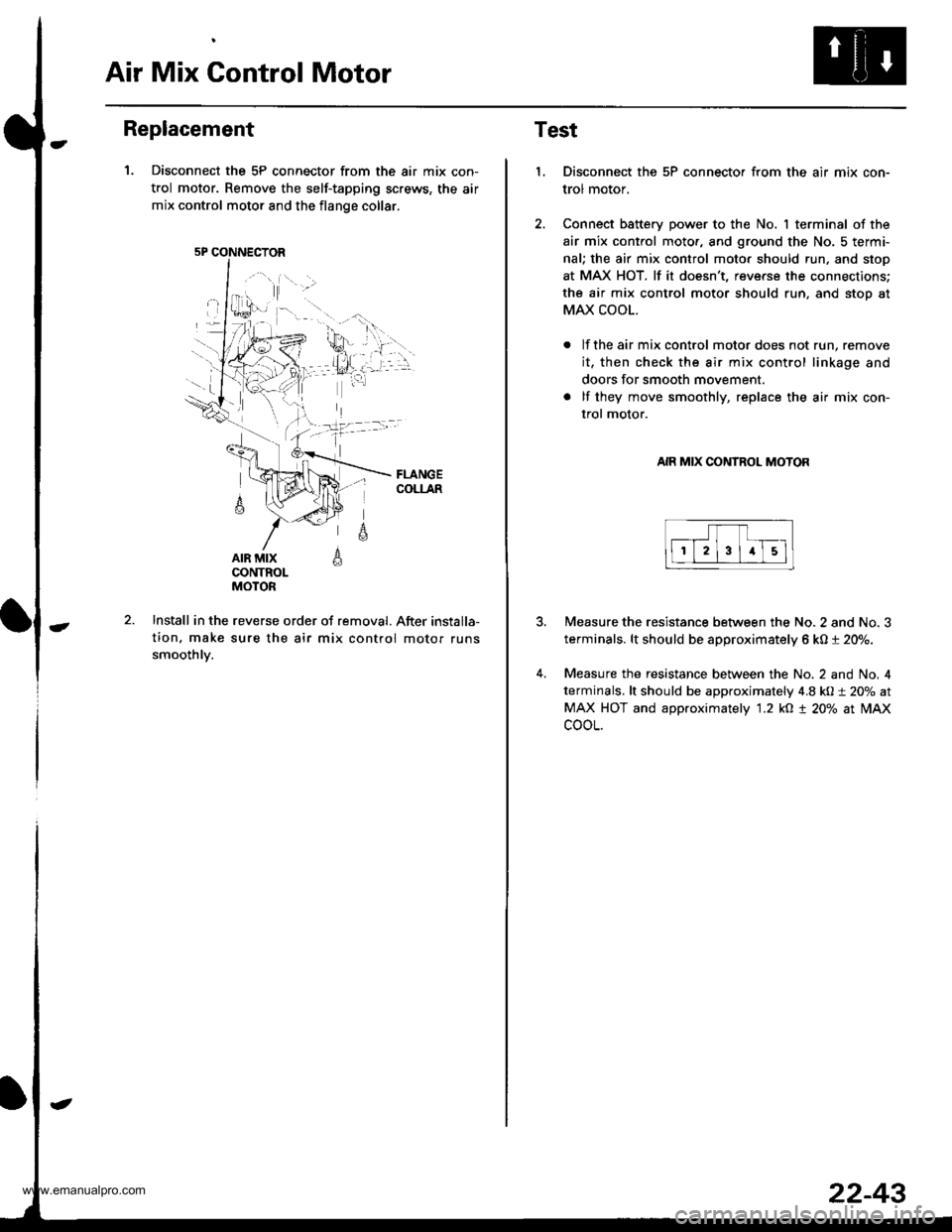
Air Mix Gontrol Motor
Replacement
1. Disconnect the 5P connector from the air mix con-
trol motor. Remove the self-tapping screws, the air
mix control motor and the flange collar.
AIR MIXCONTROLMOTOR
A
6
Install in the reverse order of removal. After installa-
tion. make sure the air mix control motor runs
smoothlv.
5P CONNECTOR
22-43
Test
1.Disconnect the 5P connector from the air mix con-
trol motor.
Connect battery power to the No. I terminal of the
air mix control moto., and ground the No, 5 termi-
nal; the air mix control moto. should run, and stop
at MAX HOT. lf it doesn't, reverse the connections;
the air mix control motor should run, and stoo at
MAX COOL.
lf the air mix control motor does not run, remove
it, then check the air mix control linkage and
doors for smooth movement.
lf they move smoothly, replace the air mix con-
trol motor.
AIR MIX CONTROL MOTOR
4.
Measure the resistance between the No. 2 and No. 3
terminals. lt should be approximately 6 kO t 20%.
Measure the resistance between the No. 2 and No, 4
terminals, lt should be approximately 4.8 kO:t 20% at
MAX HOT and approximately '1.2 kO t 20% at lilAx
cooL.
www.emanualpro.com