2000 HONDA CR-V pedal
[x] Cancel search: pedalPage 939 of 1395

6.
7.
8.
lf the clearance between the gauge body and
adjusting nut is 0.4 mm (0.02 in), the pushrod-to-
piston clearance is 0 mm. However. if the clearance
between the gauge body and adjusting nut is 0 mm,
the pushrod-to-piston clearance is 0.4 mm (0.02 in)
or more. Therefore it must be adjusted and
recheck€d.
lf clearance is incorrect, loosen the star locknut, and
turn the adjuster in or out to adjust.
. Adjust the clearance while the specified vacuum
is applied to the booster.
. Hold the clevis while adjusting.
Tighten the star locknut securely.
Remove the special tool.
0 - 0.4 mm (0 - 0.02 inl
Adjust the pushrod length as shown if the
is removed,
booster
11610.5 mm{4.6 t 0.02 inl
PUSHRODLOCKNUT1.5N.m 11.5 kgf.m. '11 lbtfl)
Install the master cylinder (see page 19-13).
9.
STAR LOCKNUT22 N.m12.2 kgt m. 16 lbtftl
10.
(Check valve is built-in)
Brake Booster Inspection
FunctionalTest
1. With the engine stopped, press the brake pedal sev-
eral times to deplete the vacuum reservoir. thenpress the pedal hard, and hold it for 15 seconds. lf
the pedal sinks, either the master cylinder is
bypassing internally, or the brake system (master
cylinder, lines, modulator, proportioning valve. or
caliper) is leaking.
2. Start the engine with the pedal pressed. lf the pedal
sinks slightly. the vacuum booster is operating nor-
mally. lf the pedal height does not vary, the booster
or check valve is faultv.
3. With the engine running, press the brake pedal light-
ly. Apply just enough pressure to hold back auto-
matic transmission creep. lf the brake pedal sinks
more than 10 mm (3/8 in.) in three minutes, the mas-
ter cylinder is faulty. A slight change in pedal height
when the Ay'C compressor cycles on and off is nor-
mal. (The Ay'C compressor load changes the vacuum
available to the booster.)
Leak Test
1.Press the brake pedal with the engine running, then
stop the engine. lf the pedal height does not vary
while pressed for 30 seconds, the vacuum booster is
OK. lf the pedal rises, the booster is faulty.
With the engine stopped, press the brake pedal sev-
eral times using normal pressure. When the pedal is
first pressed. it should be low, On consecutive appli-
cations, the pedal height should gradually rise. lf thepedal position does not vary. check the booster
check valve.
Boostor Chock Valve Test
1. Disconnect the brake booster vacuum hose at the
booster.
2. Start the engine, and let it idle. There should be vac-
uum. lf no vacuum is available, the check valve is
not working properly. Replace the brake booster
vacuum hose and check valve. and retest.
ERAKE BOOSTERVACUUM HOSE
www.emanualpro.com
Page 944 of 1395

Rear Drum Brakes
Brake Shoes Replacement (cont'd)
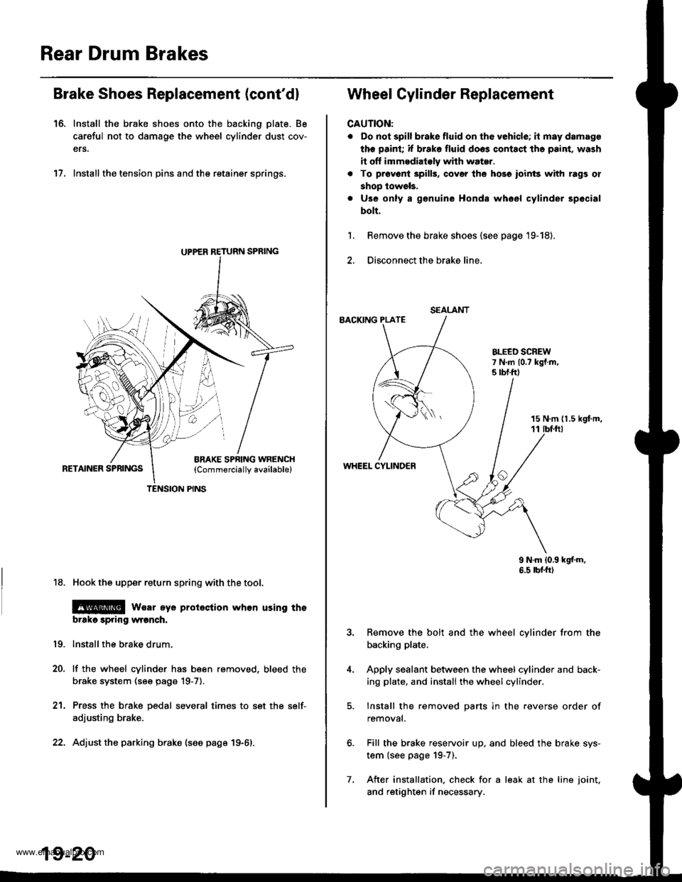
16. Install the brake shoes onto the backing plate. Be
careful not to damage the wheel cylinder dust cov-
ers.
17. Install the tension pins and the retainer springs.
18. Hook the upper return spring with the tool.
@ wsar eye proieclion whon using tho
brtko spring wronch.
lnstallthe brake drum.
lf the wheel cylinder has been removed, bleed the
brake system (see page 19-7).
Press the brake pedal several times to set the self-
adjusting brake.
Adjust the parking brako (see page 19-6).
19.
20.
21.
UPPER RETURN SPRING
TENSION PINS
19-20
7.
SEALANT
Wheel Cylinder Replacement
CAUTION:
. Do not spill brake fluid on th6 vehicle; it may damage
the paint; if brako fluid doos contact tho paint, wash
it off immedialely whh water.
. To pr6v6ni 3pills, cov6r th6 hose ioinls with rags ol
shop lowels,
. Use only a genuine Honda whoel cylinder spocial
bolt.
Remove the brake shoes {see page '19-18).
Disconnect the brake line,
BACKING PLATE
1.
15 N,m 11.5 kgt m,11 tbf.ftl
WHEEL CYLINDER
9 N.m 10,9 kgf'm.6.5 rbtft)
Remove the bolt and the wheel cylinder from the
backing plate.
Apply sealant between the wheel cylinder and back-
ing plate, and install the wheel cylinder.
Install the removed parts in the reverse order of
removal.
Fill the brake reservoir up. and bleed the brake sys-
tem {see page 19-7).
After installation. check for a leak at the line joint.
and retighten if necessary.
www.emanualpro.com
Page 951 of 1395

Anti-lock Brake System (ABS)
Features/Construction
When the brake pedal is pressed during driving, the wheels can lock before the vehicle comes to a stop. In such an event,
the maneuverability of the vehicle is reduced if the front wheels are locked, and the stability of the vehicle is reduced if the
rear wheels are locked, creating an extremely unstable condition. The ABS precisely controls the slip rate of the wheels to
ensure maximum grip force from the tires, and it thereby ensures maneuverbility and stability of the vehicle.
The ABS calculates the slip rate of the wheels based on the vehicle speed and the wheel speed, then it controls the brake
fluid pressure to attain the target slip rate.
Grip Force of Tire and Road Surlace
COEFFICIENT OFFRICTION
TARGET SLIP RATE
RADIALOIRECTIONOF THEROTATIONALDIRECTION
SLIP RATE
19-24
www.emanualpro.com
Page 957 of 1395

ABS Control Unit Terminal Arrangement
ABS CONTROL UNIT 26P CONNECTOR
Wire side of female terminals
TeiminalnumbelWiiecolorTerminal3ignTeiminalnamglDescription
Voltrge
tdminalsCondhions(lgnition Switch ON llll)Output voltago
1GRNn/VHTPCOM(Primary
common)
Power source for the solenoidvalve and pump motor.1-GNDON6
ONOV
OFFAC:3-6V
2BLI(WHTSCOM(Secondary
common)
Power source for the solenoid2-GNDOFF
lConnect the SCS seNice] connector IApprox.3 V
BLVBLU(lgnition 2)Detects ignition switch 2signal. (System activate signal)3-GNDBattery Voltage
4BLUA/ELRRO(Rear-right 0)Detocts right-rear wheelsensor srgnat.When the wheel isturned at 1 turn/second.
53 mV or above ondigitaltester (ACrange) {Beference)150 mvtrp or aboveon oscilloscope
GRYRLO(Rear-left 0)Detects left-rear wheel sensorsrgnat.6-19
8GRNFRO(Fronr-right 0)Detects right-front wheelsensor signal.8-21StopsApprox.2.5 VSTOP
{Stop)Detects bfake switch signal.(Prevents unnecessary ABS operation)9-GNDBrake pedal pressed.Battery Voltage
Brake Dedal released.OV
10BRN^/VHTFLO(Front-left 0)
Detects left-front wheel sensorsrgnal.
10-23
When the wheel isturned at 1 turn/second.
53 mV or above ondigitaltester lACrange) (Reference)
150 mvpp or aboveon oscilloscope
StopsADprox. 2.5 V
YELRL-oUT(Rearleft outlet)
Drives left-rear outlet solenoid12.GNDONONOV
OFFAC:3-6V
13RED^/vHTRR.IN(Rear-right
inlet)
Drives right-rear inlet solenoid13.GNDOFF
lConnect the SCS service\ connector IApprox. 3 V
14WHT/GRNB1(Baftery 1)Power source for the solenoidvalve and pump motor.14.GND
Every timeBattery Voltage82(Battery 2)Power source for the solenoidvalve and pump motor.15-GND
16BLKGND2(Ground 2)Ground for the ABS controlunit.16-GNDBelow 0.3 V
't7GRN/YELRR1(Rear-right 1)Detects right-rear wheelsensor signal.'t7 -4
When the wheel is turnedat l turn/second,
53 mV or aboveon digitaltester(AC range)(Reference) 150mVp-p or aboveon oscilloscope
19LT BLURL1(Rearieft 1)Detects left-rear wheel sensorsignal.19-6
GRN/BLKFR1(Front-right 1)Detects right-front wheelsensor srgnat.21-8
23GBN/ORNFL1{Front-left 1}Detects left-front wheel sensorsagnal.23-10StopsApprox. 2.5 V
REDRLI N(Rear-left inlet)
Drives left-rear inlet solenoid
25,GND
ON
=
-9ONOV
AC:3-6V
OFF
/Connect the SCS service] conneclor IApprox. 3 V
26BLKGND3(Gtound 3)Ground tor the ABS controluntI.26-GNDBelow 0.3 V
19-34
www.emanualpro.com
Page 960 of 1395

Kickback'1. The motor operates when the ABS is functioning. and the fluid in the reservoir is forced out to the master cylinder,
causing kickback at the brake pedal.
2. The ABS control unit operates the solenoid valve when the brake pedal is released after the initial diagnosis You may
hear the solenoid valve operate at this time, but it is normal
Pumo Motol
1. The pump motor operates when the ABS is functioning
2. The ABS control unit checks the pump motor operation during acceleration. You may hear the motor operate at this
time, but it is normal.
Brake Fluid Replacement/Ail Bleeding
L Brake fluid replacement and air bleeding procedures are the same as for vehicles without ABS To ease bleeding, start
with the front wheels.
Troubleshooting
1. The troubleshooting flowchart procedures assume that the cause of the problem is still present and the ABS indicator
is still on. Following the flowchart when the ABS indicator does not come on can result in incorrect diagnosis.
2. Ouestion the customer about the conditions when the problem occurred, and try to reproduce the same conditions
for troubleshooting.
Self-diagnosis is made at various times such as the initial diagnosis, except ABS control, during ABS control, during
acceleration, during the specified vehicle speed, etc. Therefore, the symptom canngt be checked unless the check
conditions match with the problem conditjons
3. When the ABS jndicator does not come on during the test-drive. but troubleshooting is performed based on the DTC,
check lor loose connectors, poor contact of the terminals, etc., before you start troubleshooting.
4. After troubleshooting, erase the DTC and test-drive the vehicle. Be sure the ABS indicator does not come on.
5. The connector illustratjons show the female terminals with a single outline and the male terminals with a double out-
l ne.
ABS Function Test
To simulate ABS operation and activate the solenoid valves and pump, use the Honda PGM Tester.
Connect the PGM Tester to the 16P Data Link Connector (DLC). When the System Select menu is displayed, select the ABS
Test Mode menu, and follow the tester's prompts.
19-37
www.emanualpro.com
Page 961 of 1395

Diagnostic Trouble Code (DTC)
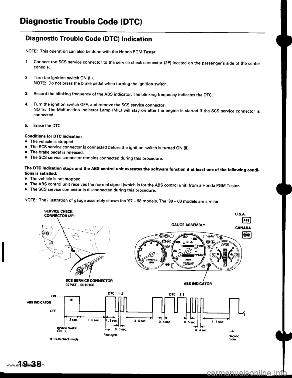
Diagnostic Trouble Gode IDTCI Indication
NOTE: This operation can also be done with the Honda pGM Tester.
1. Connect the SCS service connector to the service check connector (2P) located on the passenger's side of the centerconsote.
2. Turn the ignition switch ON (ll).
NOTE; Do not press the brake pedal whenturningthe ignition switch.
3 Record the blinking frequency of the ABS indicator. The brinking frequency indicates the DTc.
4. Turn the ignition switch OFF. and remove the SCS service connector.NOTE: The Malfunction Indicator Lamp (MlL) will stay on after the engine is startsd if the SCS seryica connecror rsconnected.
5. Erase the DTC.
Conditions for DTC indication. The vehicle is stopped.. The SCS service connector is connected before the ignition switch is turned ON flt).. The brake pedal is released.. The SCS service connector remains connected during this procedure.
The DTC indication stops and the ABS control unit axecutos tha softwaro lunction if at least one of tho following condi-tions i3 satisfiod:
. The vehicle is not stoooed.. The ABS control unit receives the normal signal (which is for the ABS control unit) from a Honda pGM Tesrer.. The SCS service connector is disconnectod during this procedure.
NQTE: The illustration of gauge assembly shows the '97 - 98 models. The '99 - oo models are similar.
SEFVICE CHECKCONNESTOR I2P}
GAUGE ASSEMBLY
A8S II{DEATOR
u.s.A.
@
CANADA
@
19-38
www.emanualpro.com
Page 962 of 1395

DTC Erasure
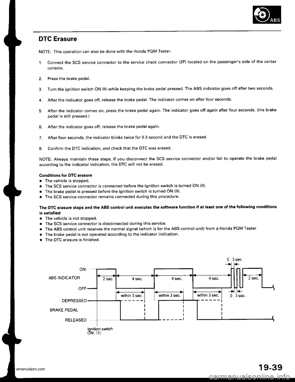
NOTE: This operation can also be done with the Honda PGM Tester.
1. Connect the SCS service connector to the service check connector (2P) located on the passenger's side of the center
console.
2. Press the brake oedal.
3. Turn the ignition switch ON (ll) while keeping the brake pedal pressed. The ABS indicator goes off after two seconds.
4. After the indicator goes off, release the brake pedal. The indicator comes on after four seconds.
5. After the indicator comes on, press the brake pedal again. The indicator goes off again after four seconds (the brake
oedal is still Dressed.)
6. After the indicator goes off, release the brake pedal again.
7. After four seconds. the indicator blinks twice for 0.3 second and the DTC is erased.
8. Confirm the DTC indication, and check that the DTC was erased.
NOTE: Always maintain these steps. lf you disconnect the SCS service connector and/or fail to operate the brake pedal
according to the indicator indication, the DTC will not be erased.
Conditions for DTC erasure
. The vehicle is stopped.
. The SCS service connector is connected before the ignition switch is turned ON (ll)
. The brake pedal is pressed before the ignition switch is turned ON (ll).
. The SCS service connector remains connected during this procedure.
The DTC erasure stops and the ABS control unit executes the software funqtion it at least one of the following conditions
b satisfied:
. The vehicle is not stopped.
. The SCS service connector is disconnected during this service.
. TheABScontrol unit receives the normal signal (which is for the ABS control unit) from a Honda PGM Tester.
. The brake pedal is not operated according to the indicator indication
. The DTC erasure is finished.
ON
ABS INDICATOR
OFF
DEPRESSED
BRAKE PEDAL
within 3 sec.0.3sec.
0.3sec.
within 3s€c. I within 3 s€c.
lonition switchdN (r)
RELEASED
19-39
www.emanualpro.com