Page 421 of 1395
'98 - 00 mod€ls:
The scan tool indicates Diagnostic Trouble code (DTc) P1457: Evaporative Emission (EVAP) Control system leak
detected (EVAP control canister system).
Troubl6shooting Flowchart('98 model only)_]
I
- The MIL has been rePorted on.- DTC P1,157 is storod.
Do the fuel tank Pressure sensor
test {see page 11-214).
ls the {ueltank pressure sensor OK?
Do the EVAP Purge contlol
solenoid valve test lsea Page 1l_
220t.
(cont'dl
11-219
www.emanualpro.com
Page 422 of 1395

Emission Control System
Evaporative Emission (EVAP) Controls (cont,dl
iTl457l ("ont'or
APCONTROLCANISTER
Ropair op€n in th6 wire betweenthe EVAP purge control 3olenoidvelve and ths ECM/PCM (A61.
VACUUMPUMP/GAUGE, O-30 iN.HgA973X - 0rl -
xxxxx
'\)
Wire side of lemale terminals
EVAP PURGE CONTROL SOI.ENOIDVALVE 2P CONNECTOR (Cl08)
PCSIRED/YELI
femaletermanals
ECM/PCM CONNECTOR A {32P}
PCS (RED/YELI
,/3 458/'t0
,,/ 14 ,/'t61718l92024
,/ 262930
JUMPERWIRE
- The MIL has been reported on.- DTC P1457 is stored.{EVAP purge control solenoidvalve test.l*
Check the EVAP purge conrrol30lenoid velve:L Disconnect the vacuum hosefrom the EVAP conlrol canis,ter, and connect a vacuumpump to the hose.2. Connect the ECM/PCM connector terminal A6 to the bodyground with a jumper wire.3. Turn the ignition switch ON (tl).4. Apply vacuum to the hose.
EVAP purge control solenoidvalve is OK. Oo the EVAP bypasssolenoid valve t€3t {see psge 1l-221t.
Does the valve hold vacuum?
Check for an open in the wire(PCS line):1. Turn the ignition switch OFF.2. Disconnect the EVAP purgecontrol solenoid valve 2P connector,3. Check for continuity betweenthe EVAP pu rge controlsolenoid valve 2P connectorterminal No.2 and bodygrouno,
ls there continuity?
Check for an open in the wire(lGl line):1. Turn the ignition switch ON t).2. Measure voltage between theEVAP bypass solenoid valve 2pcoonector terminal No. 1 andbody ground.
ls there battery voltage?
Repah open in lhe wir6 betwoenthe EVAP pu.ge cont.ol solonoidvdlvo and No. 15 ALTERNATORSP SENSOR {7.5 Al fu!€.
*: Continued frr '98 model
1-220
www.emanualpro.com
Page 424 of 1395

Emission Control System
Evaporative Emission (EVAP) Controls (cont,dl
lT145il ("ont'o)
EVAPTHREE
VATVE \'t
VACUUMPUMP/GAUGE,0 - 30 in.HsA973X - 041 -
xxxxx
WIRE
ECM/PCM CONNECTOR A {32PI
vsv
Wire side of female terminals
EVAPCONTROLCANISTER
EVAP CONTROLCANISTER VENT SHUTVALVE 2P CONNECTOR {C361}
riErr+J
I vsv
/A {Lr GRN/WHT|
YI
Wire side of female terminals
CANISTEFVENTSHUTVALVE
EVAPCONTROL
(}BING
Replace.
ffilrcr
e
(BLK/wHr)
I
11-222
EVAP control canistor vent shutvalve t6t.(The continuation of DTC p1457
troubl€ahooting.)
Chcck the EVAP control c.nirt6lvent ahut vrlve:1. Disconnect the vacuum hosetrom the EVAP thre€ way valve,and connect a vacuum pumpto the hose.2. Connect the ECM,PCM conn6c,tor terminal A4 to the bodyground with a jumper wire.3. Turn the ignition switch ON fil).4. Applyvacuum to the hose.
EVAP control crni3ter v6nt shutvelve b OK. Do the canistsr sys-lern loak test {3ee page 11-2231.
Does the valve hold vacuum?
Check for an open in the wireIVSV linGll1. Turn the ignition swjtch OFF.2. Disconnect the EVAP controlcanister vent shut valve 2pconnector.3. Check for continuity betweenthe EVAP control canister ventshul valve 2P connector termi-nal No. l and body ground.
Ropril op6n in tho wire botweonthe EVAP control canister v6ntshut v.lve and the ECM/PCM(A41.
Check tor an open in the wire(lGl line):1. Turn the ignition switch ON l).2. Measure voltage between theEVAP control canister vent shutvalve 2P connector terrninalNo. 1 and body ground.
Roplace thG EVAP cont.ol canis-ter Yent shut velve and O-ring.
Repai. opon in the wire betwoenth6 EVAP control canister vontshut valve .nd No. 15 ALTERNA-TOB SP SENSOR t?.5 Alfus6.
{LT GRN/WHT)
36a10
l4/1617l8't9202l232426 272a2930
JUMPER
www.emanualpro.com
Page 426 of 1395

Emission Control System
Evaporative Emission (EVAP) Controls (cont,dl
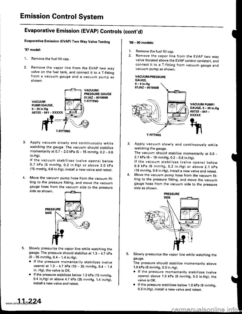
Evaporative Emission (EVAP) Two Way Valve Testing
'97 model:
1. Remove the fuelfill cap.
2. Remove the vapor Iine from the EVAP two wayvalve on the fuel tank, and connect it to a T_fittingfrom a vacuum gauge and a vacuum pump asshown.
VACUUM,/PRESSURE GAUGEotJAz - 001 rDoBT-FITTINGVACUUMPUMP/GAUGE,0 - 30 in.HgA973X-041-XXXXX
3. Apply vacuum slowly and continuouslv whilewatching the gauge. The vacuum should stabilizemomentarily at 0.7 - 2.0 kpa (5 - 1S mmHg, 0.2 _ 0.6in.Hg).
lf the vacuum stabilizes (valve opens) below0.7 kPa (5 mmHg,0.2 in,Hg) or above 2.0 kpa(15 mmHg, 0.6 in.Hg), install a new valve and retest.
4.Move the vacuum pump hose from the vacuum fit_ting to the pressure fitting, and move the vacuumgauge hose from the vacuum side to the pressureside as shown.
PiESSURESIDE
5. Slowly pressurize the vapor line while watching thegauge. The pressure should stabilize at 1.3 - 4.7 kpa(0 - 35 mmHg, 0.4 - 1.4 in.Hg).. lf the pressure momentarily stabilizes (valve
opens) at 1.3 - 4.7 kpa (10 - 35 mmHg, 0.4 _ 1.4in. Hg), the valve is OK.. lf th6 pressure stabilizes below 1.3 kpa fio mmHg,0.4 inrHg) or above 4.7 kpa (35 mmHg, 1.4 in.Hg),install a new valve and retest.
T-FITTING
11-224
.98 - 0O models:
1. Remove the fuel fill cap.2. Remove the vapor line from the EVAP two wayvalve {located above the EVAP control canister). andconnect it to a T-fitting from vacuum gauge andvacuum pump as shown.
VACUUM/PRESSUFE
VACUUM PUMP/GAUGE,0 - 30 in.HgA973X - 041 -
xxxxx
5.
Apply vacuum slowly and continuously whilewatching the gauge.
The vacuum should stabilize momentarily at O.g _
2.1 kPa (6 - 16 mmHg, 0.2 - 0.6 in.Hg).lf the vacuum stabilizes (valve opens) below0.8 kPa (6 mmHg, 0.2 in.Hg) or above 2.1 kpa(16 mmHg, 0.6 in.Hg), install a new valve and retest.Move the vacuum pump hose from the vacuum fit-ting to the pressure fitting. and move the vacuumgauge hose from the vacuum side to the pressure
side as shown.
Slowly pressurize the vapor line while watching thegauge.
The pressure should stabilize momentarilv above1.0 kPa (8 mmHg, 0.3 in.Hg).a lf the pressure momentarily stabilizes (valve
opens) above 1.0 kPa (8 mmHg. 0.3 in.Hg), thevalve is OK.. lf the pressure stabilizes below ,|.0 kpa {g mmHg.0.3 in.Hg), install a new valve and retest.
T-FITTING
www.emanualpro.com
Page 572 of 1395

Troubleshooting Procedures
Checking ths Diagnostic Trouble Code (DTC)
with an O8D ll Scan tool or Honda PGM Tsster
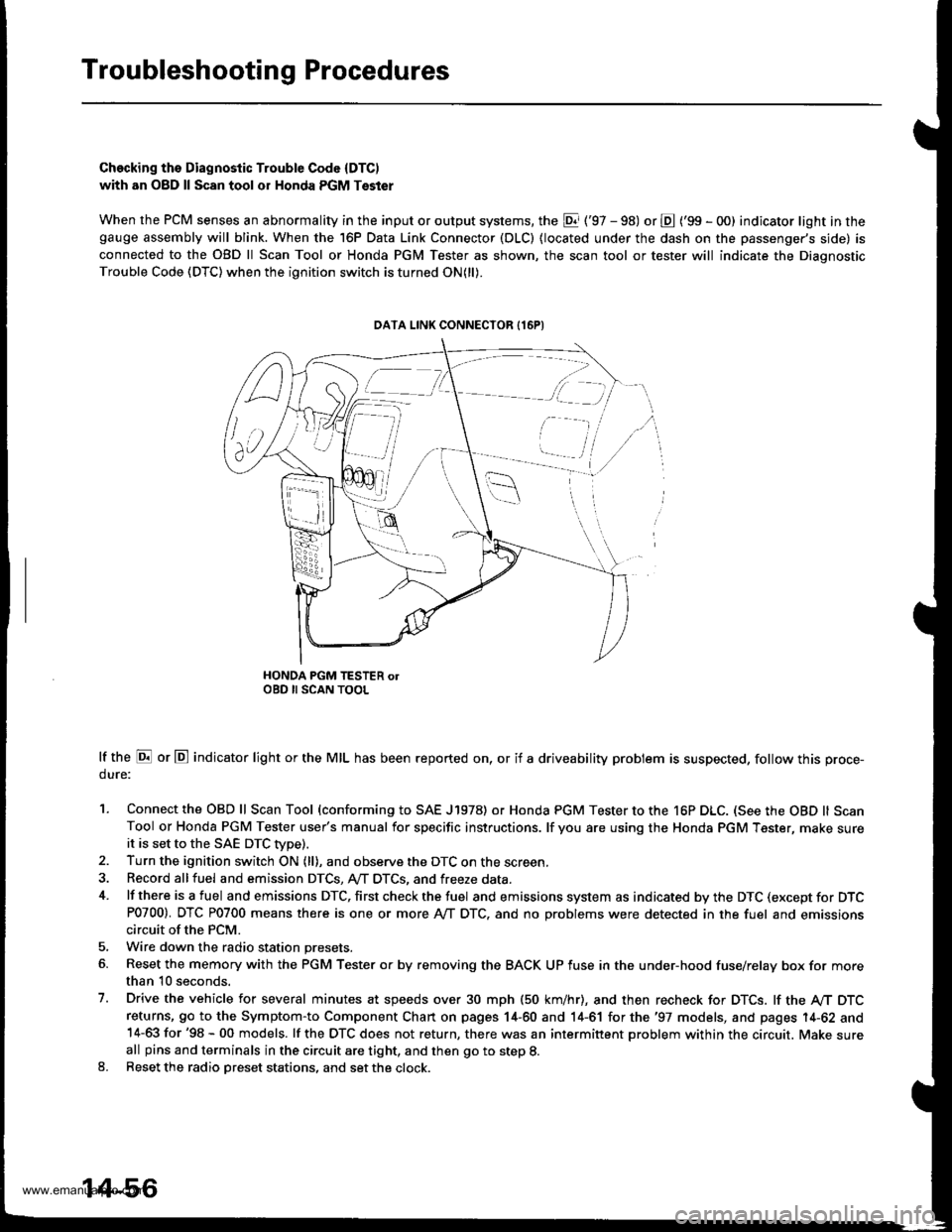
When the PCM senses an abnormality in the input or output systems, the El ('97 - 98) or E ('99 - O0) indicator light in thegauge ass€mbly will blink. When the 16P Data Link Connector (DLC) {located under the dash on the passenger's side) is
connected to the OBD ll Scan Tool or Honda PGM Tester as shown, the scan tool or tester will indicate the Diagnostic
Trouble Code (DTC) when the ignition switch is turned ON(ll).
HONDA PGM TESTER olOBD II SCAN TOOL
lf the E or E indicator light or the MIL has been reported on, or if a driveability problem is suspected, follow this proce-
dure:
1. Connect the OBD ll Scan Tool (conforming to SAE J1978) or Honda PGM Tester to the 16P DLC. (See the OBD ll ScanTool or Honda PGM Tester user's manual for specific instructions. lf you are using the Honda PGM Tester, make sureit is set to the SAE DTC Wpe).2. Turn the ignition switch ON (ll), and observe the DTC on the screen
3. Record allfuel and emission DTCS, A,,/T DTCS, and freeze data.
4. lf there is a fuel and emissions DTC, first check the fuel and emissions system as indicated by the DTC (except for DTCP0700). DTC P0700 means there is one or more Ay'T DTC, and no Droblems were detected in the fuel and emissionscircuit of the PCM.
5. Wire down the radio station presets.
6. Reset the memory with the PGM Tester o. by removing the BACK UP fuse in the under-hood fuse/relay box for morethan 10 seconds.
7. Drive the vehicle for several minutes at speeds over 30 mph (50 km/hr), and then recheck for DTCS. lf the A/T DTCreturns, 9o to the Symptom-to Component Chart on pages 14-60 and 14-61 for the '97 models, and pages 14-62 and14-63 for '98 - 00 models. lf the OTC does not return, there was an intermittent problem within the circuit. Make sureall pins and terminals in the circuit are tight, and then go to step 8.8. Reset the radio Dreset stations, and set the clock.
DATA LINK CONNECTOR {16PI
[ -=.r,
ili,i /i,
v,., i
14-56
www.emanualpro.com