Page 798 of 1395

Description
Hydraulic Flow (cont'dl
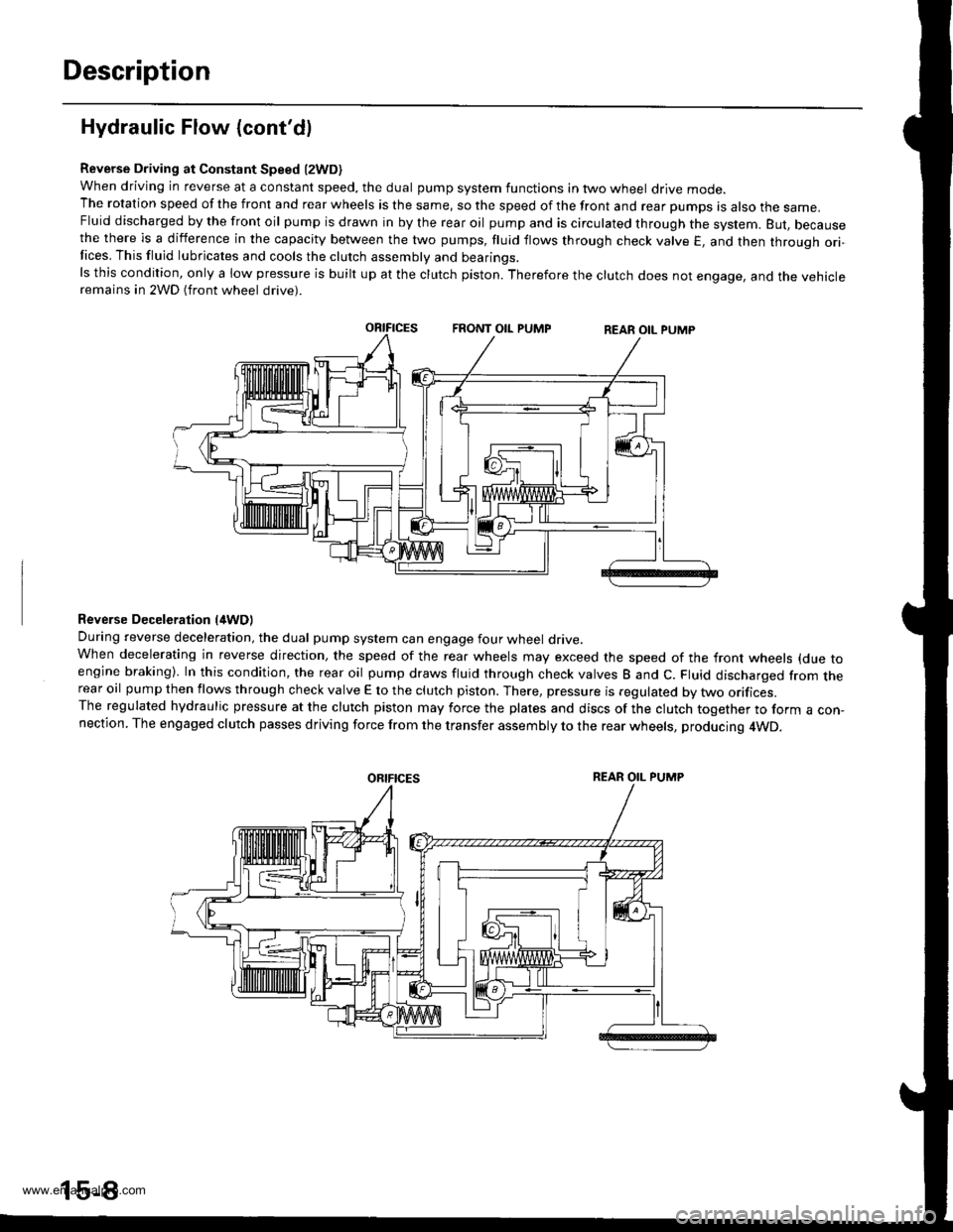
Reverse Driving at Constant Speed l2WD)when driving in reverse at a constant speed, the dual pump system functions in two wheel drive mode.The rotation speed of the front and rear wheels is the same, so the speed of the front and rear pumps is also the same,Fluid discharged by the front oil pump is drawn in by the rear oil pump and is circulated through the system. But, becausethe there is a difference in the capacity between the two pumps, fluid flows through check valve E, and then through ori-Iices. This fluid lubricates and cools the clutch assembly and bearings.ls this condition, only a low pressure is built up at the clutch piston. Therefore the clutch does not engage, and the vehicleremains in 2WD (front wheel drive).
Reverse Deceleration l/tWDl
During reverse deceleration, the dual pump system can engage four wheel drive.When decelerating in reverse direction, the speed of the rear wheels may exceed the speed of the front wheels (due toengine braking). In this condition, the rear oil pump draws fluid through check valves B and C. Fluid discharged from therear oil pump then flows through check valve E to the clutch piston. There, pressure is regulated by two orifices.The regulated hydraulic pressure at the clutch piston may force the plates and discs of the clutch together to form a con,nection. The engaged clutch passes driving force from the transfer assembly to the rear wheels, producing 4WD.
oRtFtcEsREAR OIL PUMP
www.emanualpro.com
Page 805 of 1395
Rear Differential Assembly
lllustrated Index
O.RINGReplace.
6xl.0m12 N.m (1.2 kgf m,8.7 lbt'ftl
BACK-UP RING
COMPANION FLANGE
CLUTCH HUB/PLATES/DISCS
DIFFERENNAL CLUTCHASSEMBLY
DOWEL PINS
OIL PUMP DRIVESHAFT
LOCKNUT, 24 mmReplace.118 N.m (12.0 kgtm.87 rbt ft)
OIL SEALReplace.
PRESSURE PLATE
THBUST NEEDLEAEARING""t",at\(
'd'
CLUTCH GUIDE
OIL PUMPPIN
e
MAGNET
6x1.0mm12 N.m 11.2 kgt'm,8.7 lbf'ft|
OIL STRAINER
15-15
www.emanualpro.com
Page 812 of 1395
Rear Differential Assembly
Disassembly (cont'dl
9. Remove the shim and the clutch quide.
d"HIM'30mm
CLUTCH GUIDE
Remove the clutch hub/plates/discs and the pressure
prare.
10.
CLUTCH HUB/PLATES/OISCS
k
ffi-:*
_zz PRESSURE PLArE
@-
15-22
11. Remove the thrust needle bearing and the oil pump
driveshaft.
Remove the oil pump body assembly, the oil pump
pin, the magnet, and the oil strainer.
OIL PUMP BODY ASSEMBLY
MAGNET
OIL PUMP PIN
12.
OIL STRAINERInspect for damageor clogging.
www.emanualpro.com
Page 813 of 1395
Reassembly
1. Apply CVT fluid to the rubber of the oil strainer, then
install the oil strainer, the magnet, and the oil pump
pin to the differential carrier.
OIL PUMP PIN
DIFFERE]TTIAL CARRIERASSEMBLY
Align the oil pump pin with the groove of the rear oil
pump in the pump body assembly, then install the oil
pump body assembly to the differential carrier assem-
oty.
-n
CWfluid
2.
MAGNET
OIL PUMP BODY ASSEMBLY
3. Tighten the oil pump body assembly mounting
bolts.
4. Install the oil pump driveshaft by aligning the pro-
jection of the oil pump driveshaft with the groove of
the front oil pump in the oil pump body assembly.
lnstall in this direction.
Projection
6x1.0mm12 N.m 11.2 kg{.m,8.7 lbl.ft}
Install the thrust needle bearing.
Install the pressure plate assembly by aligning the
projection of the pressure plate with the groove of
the oil pump driveshaft.
5.
OIL PUMPDRIVESHAFT
(cont'd )
15-23
THRUST NEEDLE BEABING
PRESSURE PLATE
www.emanualpro.com
Page 852 of 1395

Uneven or rough steering.Ad,ust the rack gu ide (see page 17- 15).
ll the problem is not corrected byadjusting the rack guide, replacethe gearbox.
Adjust the belttension. Replace thebelt, if necessary (see page 17-14).Belt slipping on pulley.
lf the engine stalls when thewheel is turned while the vehicleis stopped or moving at lowspeed, adjust the idle speed (seesection 111.
ldle speed low or erratic.
Check power steering lluid level. lfthe level is excessively low checkfor leaks in the system. Add fluidto the specified level.
Air in reservoir, or check powersteering tluid level.
lf fluid level is OK, check O-ringsand seals on both ends of thepump inlet hose, and the P/Spump housing mating surlacesand drive shaft oil seal for suction leaks. Check the reservoir forcracks, Replace parts as neces-
Pump belt slipping on pulley(pump stops momentarily).Adjust the belt tension (see page17-14) or replace belt.
Check if pump pressure is normaland the gauge needle travel is 500kPa (5 kgl/cm,, 71 psi) or less.Check the flow control valve if theneedle travel exceeds 500 kPa (5kgflcm'�, 71 psi). lI the flow controlvalve is normal, replace the pumpas an assembly,
Install the power steering pres-sure gauge, Close the pressurecontrol valve and shut off valve (if
so equipped) fully and measurethe pump pressure (see page 17-16ot 17 17).
Steering wheel kicks backduring wide turns.
7-7
www.emanualpro.com
Page 854 of 1395
Pump noiseGrating nois€trom pump
Pump noise
Raftle or chattering
Check the fluid lev€1.lt low, fill the reservoir to theproper level. and check for leaks.Tighten or roplace as necessary,
Cavitation caused by air bubblesin the fluid.
Check for a crushed inlet hose ora loose hose clamp allowing airinto the suction side of the system. Check the reservoir forcracks. Tighten or replace as nec-
Check the drive shaft oil seal.
Pump noise up to 2 - 3 minutesafter starting in cold weather isnormal, Compare pump noise atoperatrng temperature to anothervehicle.
ll pump noise is abnormally loud,remove and inspect the pump forwear and damage (see page 17-251.
Tighten or replace the pulley.lI shaft is loose, replace thepump.
17-9
www.emanualpro.com
Page 855 of 1395

Troubleshooting
Fluid Leaks
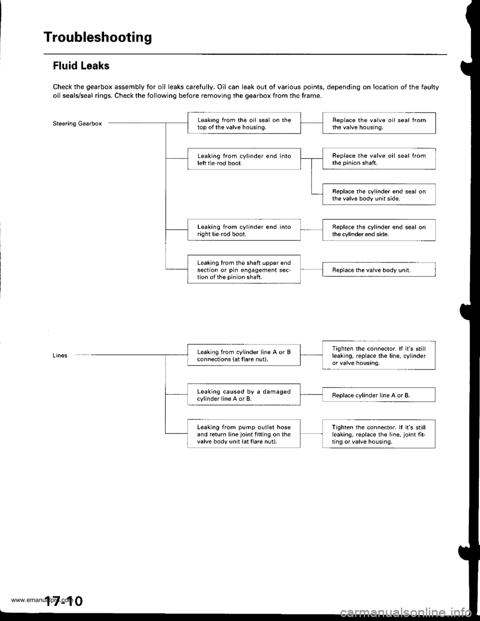
Check the gearbox assembly for oil leaks carefully. Oil can leak out ot various points, depending on location of the faulty
oil seals/seal rings. Check the following before removing the gearbox from the frame.
Steering GearboxLeaking from the oil seal on thetop of the valve housing.Replace the valve oil seal fromthe valve housing.
Leaking from cylinder end intoleft tie rod boot.Replace the valve oil seal fromthe pinion shaft.
Replace the cylinder end seal onthe valve body unit side.
Leaking from cylinder end intoright tie-rod boot.Replace the cylinder end seal onthe cylinder end side.
Leaking lrom the shaft upper endsection or pin engagement sec-tion of the pinion shaft.Replace the valve body unit.
Tighten the connector. It it's stillleaking, replace the line, cylinderor valve housing.
Leaking from cylinder line A or Bconnections (at tlare nut).
Leaking caused by a damagedcylinder line A or B.Replace cylinder line A or B.
Leaking from pump outlet hoseand return line joint fitting on thevalve body unit {at tlare nut}.
Tighten the connector. ll it's stillleaking, replace the line, joint fit-ting or valve housing,
17-10
www.emanualpro.com
Page 873 of 1395

Power Steering Pump
Reassembly
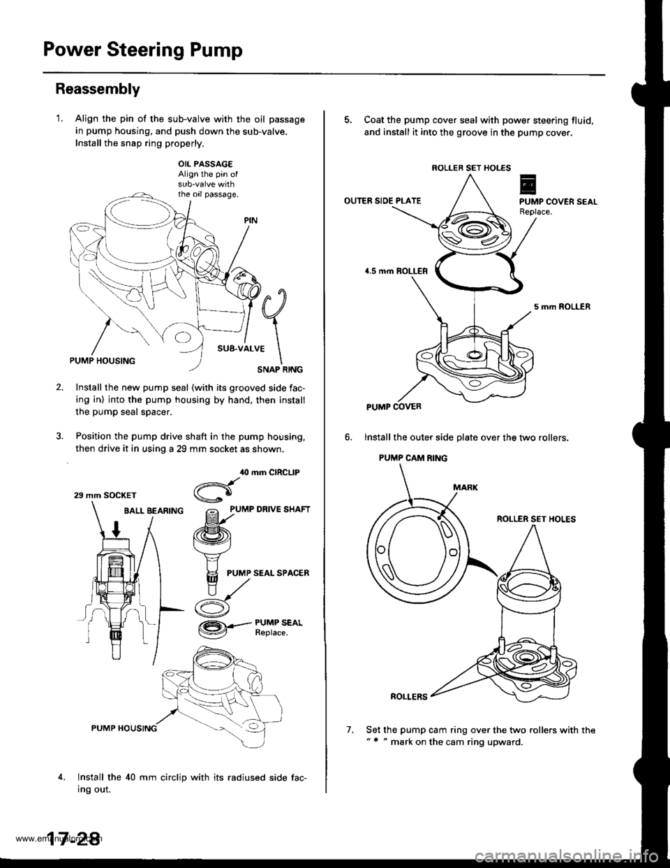
'1.Align the pin of the sub-valve with the oil passage
in pump housing, and push down the sub-valve.
Install the snsp ring properly.
OIL PASSAG€Align the pin of
the oil passage.
#q
;1..*
\SNAP RINGPUMP HOUSING
Install the new pump seal (with its grooved side fac-
ing in) into the pump housing by hand, then install
the pump seal spacer.
Position the pump drive shaft in the pump housing,
then drive it in using a 29 mm socket as shown,
BALL BEARfNG grlu,e un.t
/ /ffi\
1 / t\v4
t/ Y
# I F
PUMP SEALSPAC,ER
ry^
i- d
,O mm CIRCLIP
Hgo
/= PUMP DRIVE SHAFT
@.--#$i":*'
4,
PUMP HOUSING
Install the 40 mm circlip with its radiused side fac-
Ing out.
29 mm SOCKET
17 -2A
7.
5. Coat the pump cover seal with power steering fluid,
and install it into the groove in the pump cover.
OUTER SIDE PLATE
5 mrh ROLLER
lnstall the oute. side plate over the two rollers.
PUMP CAM RING
ROLLER SET HOLES
ROLLERS
Set the pump cam ring over the two rollers with the"' " mark on the cam ring upward.
ROLLER SET HOLES
PUMP COVER
www.emanualpro.com