Page 620 of 1395
Electrical Troubleshooting ('98 - 00 Model)
Troubleshooting Flowchart - A/T Gear Position Switch (Open) (cont'd)
PCM CONNECTORS
B {25Ptc (31P|
LGl IERN/BLKI
Wire side of female terminals
LGl {BRN/BLKI
LGl {BRN/ELXI
From page 14-103
Me.sure ATP D4 Vohrge:1. Shift to E 1'98) or E ('99 -
00) position.2. Measure the voltage betweenthe Dg and 820 or 822 termi-nats.
Repair opon in th6 wire betweentho m tarminal and the A/T gealposition swhch.
Me..ure ATP 03 Vohage l'98modell:1. Shift to E position.2. Measure the voltage betweenthe DB and 820 or 822 tetmi-nals,
Repair open in the wire botwoonth6 08 terminal .nd the A/T geatposition switch (381.
Measuro ATP 2 Voltage:1. Shilt to E position.2. Measure the voltage betweenthe D14 and 820 or 822 terminats.
Repair opon in the wire betweenthe D14 t€.minal end the A,/Tgear po3ition switch,
To page 14 105
www.emanualpro.com
Page 621 of 1395
From page 14-104
Measure ATP 1 Voliag€:1. Shift to E position.2, Measure the voltage betweenthe D15 and 820 or B22 termi-nals.
Repair open in the wire betweenthe D15 terminal and the A/Tgear poaition switch.
Check LG Wire tor an OpenCircuit:'1. Turn the ignition switch OFF.2. Check lor continuity betweenthe 820 terminal and bodyground, and between the 822terminal and body ground.
Repair open in th. wiresbetween the B20 and 822 tarmi-nals and body ground. and repairpoor ground {G101).
ls there continuity?
Check tor loose terminaltit in thePCM connectors. lf n6cassary,substitute d known-good PCMand recheck.
B t25Pl
FCM CONNECTORS
c t3lPtD tl6Pl
LGl IBRN/BLKI
LGl (BRN/BLKI
Wire side of female terminals
A (32P1B (2sP)c (31P|
14-105
www.emanualpro.com
Page 638 of 1395
Electrical Troubleshooting {'gB - 00 Models}
Troubleshooting Flowchart - Shift Control System (cont,d)
From page 14 121
Replace Shilt Cont.ol SolenoidValve A$ambly and Recheck:'1. Replace the shift controlsolenoid valve A/B assembly(see page 14-136) and the lin,ear solenoid assembly (seepage 14138).2. Turn the ignition switch OFFand reset the PCM memory byremoving the BACK UP (7.5 A)tuse in the !nder-hood luse/relay box for more than 10seconos.3. Drive the vehicle at over '12
mph (20 km,/ti) in lst,2nd,3rd,and 4th gear tor more than 30seconds in E position.4. Recheck for code P0730 (41).
Does the OBD ll scan toolindicate code P0730 or doesthe E orE indicator lightindicate code 41?
Tho system is OK .l this tim€.
www.emanualpro.com
Page 640 of 1395

Electrical Troubleshooting ('98 - 00 Modelsl
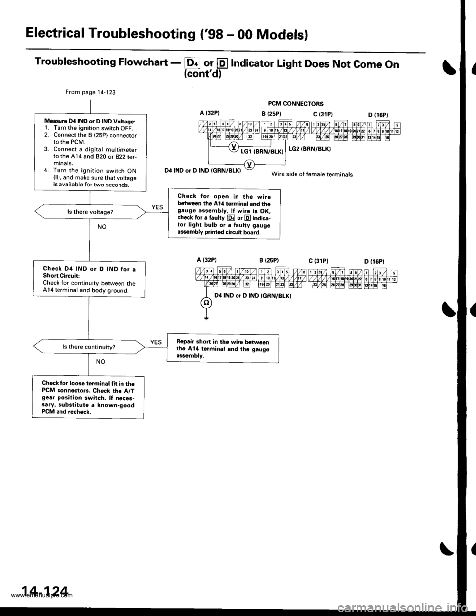
Troubleshooting Flowchart - E or @ Indicator Light Does Not come on(cont'd)
PCM CONNECTORS
B {25P} C (3D (16P1
n f,-ff nt f,Fjrti.trnnmflnr
D4 INO or D IND IGRN/BLKI
From page 14-123
Measure D4IND or D lNDVoh.ge:'L Turn the ignition switch OFF.2. Connect the B (25Plconnector
to the PCM.3. Connect a djgital multimeterto the A14 and 820 or B22 terminals,4. Turn the ignition switch ON(ll), and make sure that voltageis available for two seconds.
Check lor open in the wireb€tween the Al/t terminal .nd thegeugo a$eftbly. lf wi.a is OK.check tor a fautty E or E indica-tor light bulb or a faulty gaugeass€mbly p.inted circuit board.
Check D4 IND or D IND for aShort CircuitiCheck for continuity between theA14 terminal and body ground.
Ropair short in tha wiro b€twesnthe A14 termin.l and th€ gaugo.ssemblv.
Check tor looso telminal tit in thePCM connoctors. Chock the A/Tgear position swiich. It neces-3ary, substitute a known-goodPCM and rech€ck.
c (31P)
LG2 (BRN/BLKI
Wire side of female terminals
D {16P)
D4 IND or D IND
14-124
www.emanualpro.com
Page 641 of 1395

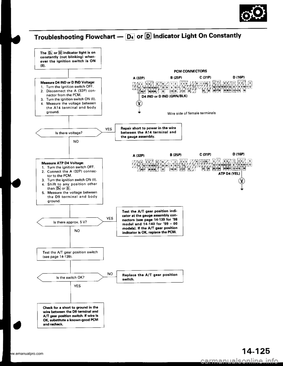
The E or E indicator light is on
constantly (not blinkingl when-
ev€r lhe ignition switch is ON
0.
Me.3rtre D4IND o. D IND Vottage:
1. Turn the ignition switch OFF.
2. Disconnect the A (32P) con-
nector from the PCM.
3. Turn the ignition switch ON (ll)
4. Measure the voltage between
the A14 terminal and bodyground.
Repair short to power in the wire
b€iween th€ A14 terminal and
the gauge a$.mbly.
Measuro ATP D4 voltage:1. Turn the ignition switch OFF2. Connect the A (32P) connec-
tor to the PCM.
3. Turn the ignition switch ON (ll)
4. Shi{t to any position other
than E or E.5. Measure the voltage betweenthe D9 terminal and bodyground.
T6st the A/T g.ar Po3ition indi-
cator at the gauge e$embly con_
nectorc (se€ P.go 1,1-139 lor '98
model .nd 14-140 for '99 - 00
modelsl, f the A/f gear Poshionindicator is OK, replace the FCM.
ls there approx.5 V?
Test the A/T gear position switch(see page 14-139i.
Check for r 3hofi to ground in thewire betweon tho IXI teYminal andA/T gear position switch. lf wire is
OK subBtihrte a known-good PCM
and recheck.
Troubleshooting Flowchart - E or E Indicator Light On Gonstantly
PCM CONNECTORS
B (25P)
11 tr. //at tonl /1! /1/ /llt /
t',lxr uu?l Lrfr4
{GRN/BLKI
D lr6Pl
F't!4[r
Wire side of female terminals
c t3lPl_=---r-:=-t rl3l/ 5/, ?eV t r?V t
t/l,4lzulErt!t!!j!t!u3t ll]]lll1lglt]|b AE A.W6l ld$!'lLM.l1t I r.i
ATP D' (YEL) II
O)
I
A {32P)
D4 IND or D IND
c (3'tP)
A l32Pl
14-125,
www.emanualpro.com
Page 646 of 1395

Electrical Troubleshooting ('98 - 00 Models)
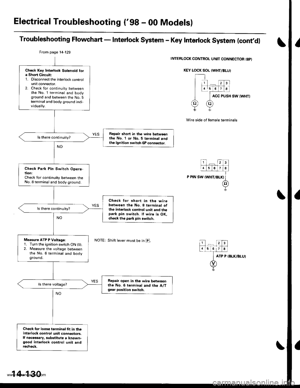
Troubleshooting Flowchart - Interlock System - Key Interlock System (cont,dl
INTERLOCK CONTROL UNIT CONNECTOR {8PI
KEY LOCK SOL (WHT/BI-U}
ACC PUSH SW {WHT)
Wire side of female terminals
ATP P IBLK/BLUI
From page 14'129
Shift lever must be in E.
Check Key Intorlock Solonoid tola Short Circuit:1. Disconnect the interlock controlunit connector,2. Check for continuity betweenthe No. l terminal and bodyground and between the No.5terminal and body ground individually.
Repair shon in thc wire betweonthe No. 1 or No. 5 terminal andth€ ignhion switch 6P connector.
ls there continuity?
Check Park Pin Switch Opera-tion:Check for continuity between theNo. I terminal and body ground.
Check for short in the wir6between the No. 8 terminal ofthe int€rlock control unit and thopark pin switch. ll wire is OK,ch6ck the park pin switch.
ls there continujty?
Moasure ATP P Voftegel1. Turn the ignition switch ON (lli.2. Measure the voltage betweenthe No. 6 terminal and bodyground.
Repair open in the wiro betweenthe No. 6 termin.l and the A/Tgear position 3witch.
Check for looseterminal fit in th€interlock control unit connoctors.lf necosssry, substitute t known-good interlock control unit andrecheck.
14-130
www.emanualpro.com
Page 655 of 1395
A/T Gear Position Switch
Test
1. Remove the A,/T gear position switch connsctor from the connector bracket, then disconnect the IVT gear position
switch connector (10P).
2. Check for continuity between the terminals in each switch position according to the table below.
A/T GEAR POSITIONSWITCH CONNECTOR(10P1
A/T Gear PGition Swhch Coniinuity Ch6ck'97 - 98 Models
Wire side oI female terminals
\_-__l"'ry1
Position
'l76o10
tro--o
tro------o
t!l!lo-----o
Eo_----o
Eo_-----o
Eo----o
Eo-----o
'99 - O0 Models
\______lg,-r4
Position1467.'l0
tro----o
trc\----o
Eo-----o
Eo--o
Eoo
Eo_----c
NOTE: Terminal No.3: Neutral oosition switch
14-139
www.emanualpro.com
Page 656 of 1395
A/T Gear Position Switch
Replacement
@ Make 3ure lifts, iacks, and safety stands
ar€ placod properly lsoo soction 1).
1. Raise the front of the vehicle, and support it with
safety stands (see section 1).
2. Set the parking brake, and block both rear wheels
securely.
3. Shift to E position.
Remove the A/T gear position switch connector
from the connector bracket, then disconnect it.
Remove the AfI gear position switch harness clamp.
5x1.0mm12Nm11.2kgf.m,8.7 tbf.fttBRACIGT
14-140
6. Remove the harness clamp from the end cover,
then remove the Aff gear position switch cover and
Ay'T gear position switch.
A/T GEAF POSITIONswrTcH covER6x1.0mm12 N.m 11.2 kgt m.8.7 lbf.ftl
1.Set the IVT gear position switch to E position. The
AfI gear position switch clicks in E position.
POSmON
6x1.0mm12 N.m
{1.2 kg{.m,8.7 lbtftl
swlTcH
www.emanualpro.com