Page 1205 of 1395

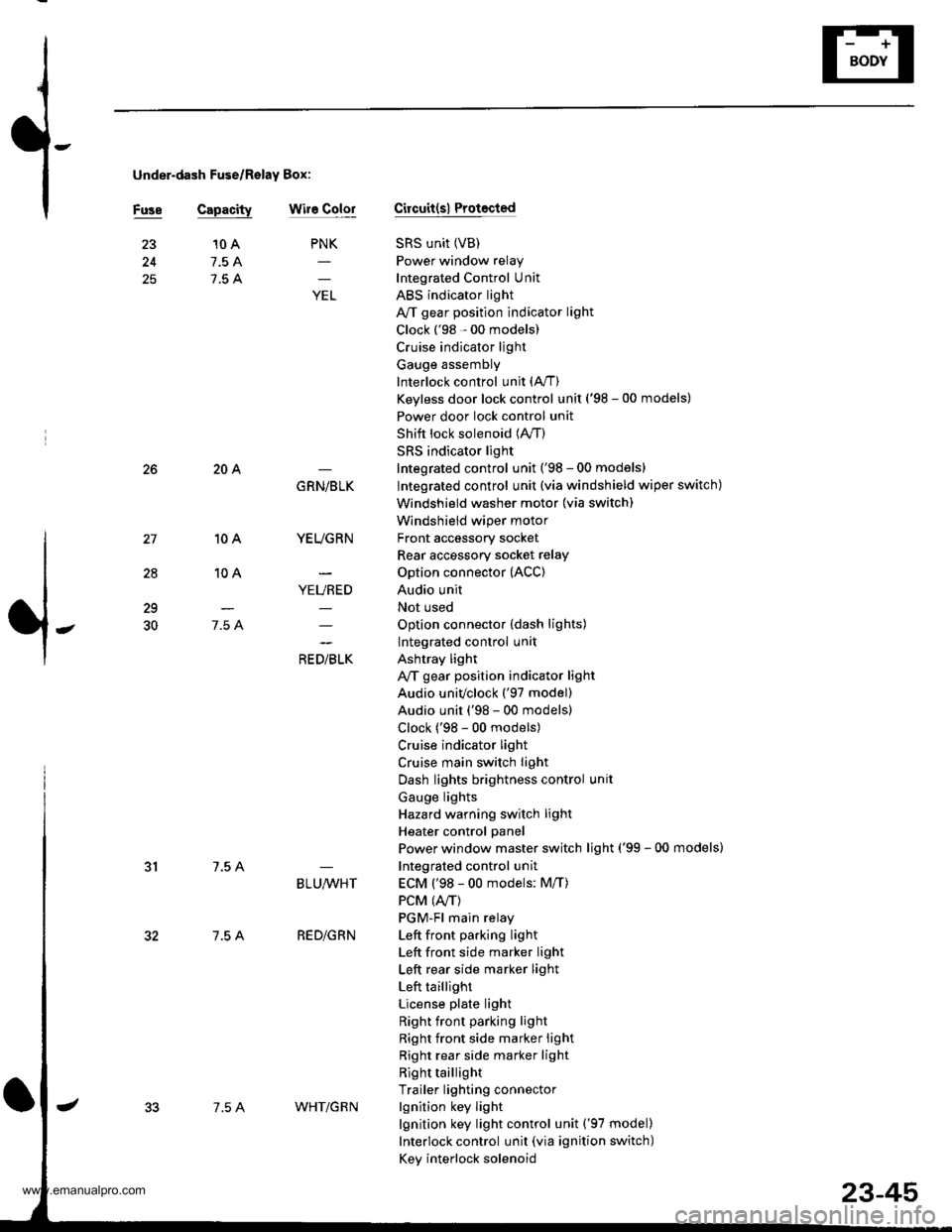
under-dash Fuse/Relay Box:
Fuse Capacitywir6 ColorCircuit(sl Protocted
SRS unit (VB)
Power window relay
Integrated Control Unit
ABS indicator light
A/T gear position indicator light
Clock ('98 - 00 models)
Cruise indicator light
Gauge assembly
Interlock control unit (A,/T)
Keyless door lock control unit ('98 - 00 models)
Power door lock control unit
Shift lock solenoid (lVT)
SRS indicator light
Integrated control unit ('98 - 00 models)
Integrated control unit (via windshield wiper switch)
Windshield washer motor (via switch)
Windshield wiper motor
Front accessory socket
Rear accessory socket relay
Option connector (ACC)
Audio unit
Not used
Option connector (dash lights)
Integrated control unit
Ashtray light
A,/T gear position indicator light
Audio univclock ('97 model)
Audio unit ('98 - 00 models)
Clock ('98 - 00 models)
Cruise indicator light
Cruise main switch light
Dash lights brightness control unit
Gauge lights
Hazard warning switch light
Heater control panel
Power window master switch light ('99 - 00 models)
Integrated control unit
ECM ('98 - 00 models: M/T)
PCM (4./T)
PGM-Fl main relay
Left front pa.king light
Left front side marker light
Left rear side marker light
Left taillight
License plate light
Right front parking light
Right front side marker light
Right rear side marker light
Right taillight
Trailer lighting connector
lgnition key light
lgnition key light control unit ('97 model)
Interlock control unit (via ignition switch)
Key interlock solenoid
25
PNK
;
10 A
7.5 A
7.5 A
28
10A
10A
7.5 A
204
7.5 A
7.5 A
GRN/BLK
YEUGRN
YEURED
a, olrL"
29
30
BLU,ryVHT
RED/GRN
7.5 AWHT/G R N
23-45
www.emanualpro.com
Page 1206 of 1395

Ground Distribution
Ground-to-Component(sl Index
GroundWire Color
G2
G3
G 10'l
G201
G202
G351
BLIVRED
BRN
BLK
BLK
BRN/BLK
BLK
BLK
BLK
23-46
Component or Circuits Grounded
Battery
Valve Cover
Transmission housing
A,/T gear position switch
ECM (PG1, PG2) ('98 - 00 models: M/T)
PCM (PG1, PG2l (Avrr)
PGM-FI main relay
Power steering pressure (PSP) switch
Radiator fan switch
VSS
Data link connector
ECM (1G1, LG2) ('98 - 00 models: M/T)
PCM (LGI, LG2) (IVT)
Shielding:
between ECM ('98 - 00 models: M/T) or PCM (Ay'T) and CKF sensorbetween ECM {'98 - 00 modets: M/T} or pCM (Ay'T) and CKp sensorbetween ECM ('98 - 00 models: M/T) or PCM (rVT) and CYP sensorbetween ECM ('98 - 00 models: M/T) or PCM (Ay'T) and TDC sensorbetween ECM {'98 - 00 models: M/T) or PCM (ly'T) and countershaft speed sensor (Ay'T)
between ECM ('98 - 00 models: M/T) or PCM {A,,/T) and mainshaft sp€ed sensor {!VT)between ECM ('98 - 00 models: M/T) or PCM (A,/T) and primary HO2Sbetween ECM ('98 - 00 models: M/T) or PCM (Ay'T) and secondary HO2SHorn (High)
Horn {Low}
Radiator fan motor
Right headlight
Right front parking light
Right front side marker light
Right front turn signal light
Condenser fan motor
Cruise actuator
Left front parking light
Left front side marker light
Left front turn signal light
Left headlight
Rear window washer motor
Windshield washer motor
ABS pump motor
www.emanualpro.com
Page 1207 of 1395

BLKG401
GroundWir€ ColorComponent or Circuits Grounded
ABS indicator circuit
ABS control unit
Ashtray light
A/T gear position indicator dimming circuit
Brake fluid level switch
Clock ('98 - 00 models)
Clutch inrerlock switch (M/T)
Clutch switch (Mff)
Cruise main switch
Cruise indicator circuit
Cruise control unit
Dash lights brightness controller
Data iink connector
Daytime running rights control unit (Canada)
Front accessary socket
Gauge and indicators
Heater control panel
lgnition key light control unit ('97 model)
lgnition key switch
Integrated control unit
Interlock control unit (Ay'T)
Parking pin switch {A,/T)
Power window relay
Rear accessary socket relay
Bear window defogger relay
Rear window wiper control unit ('97 model)
Service check connector
Spotlights
SRS indicator circuit
Turn signal/hazard relay
Windshield wiper motor
Windshield wiper/washer switch- plus everything grounded through G402
ABS control unit
Blower motor relay
Blower motor high relay
ELD unit (USA)
Power transistor- plus everything grounded through G401
BLKG402
{cont'd)
23-47
www.emanualpro.com
Page 1208 of 1395
Ground Distribution
Ground-to-Component(sl Index (cont'dl
Wire ColorGround
G552
G501
G801
BLK
BLK
BLK
BLK
Component or Circuits Grounded
Audio unit
Driver's door lock actuator (door lock knob switch)
Driver's door lock switch
Driver's power window motor
Keyless door lock control unit ('98 - 00 models)
Power door lock control unit
Power mirror switch
Power window master switch
Driver's seat belt switch
Fuel gauge sending unit
Fuel pump (FP)
Left rear side marker light
Left taillight
Rear accessary socket
Right rear side marker light
Trailer lighting connector
High mount brake light
Rear window defogger
Rear window wiper motor
Rjght taillight- plus eveMhing grounded through G631
Hatch glass opener solenoid
License plate light- plus eveMhing grounded through G6l1
SRS unit
BLK
BLK
BLK
23-48�
www.emanualpro.com
Page 1214 of 1395

lgnition Switch
Test
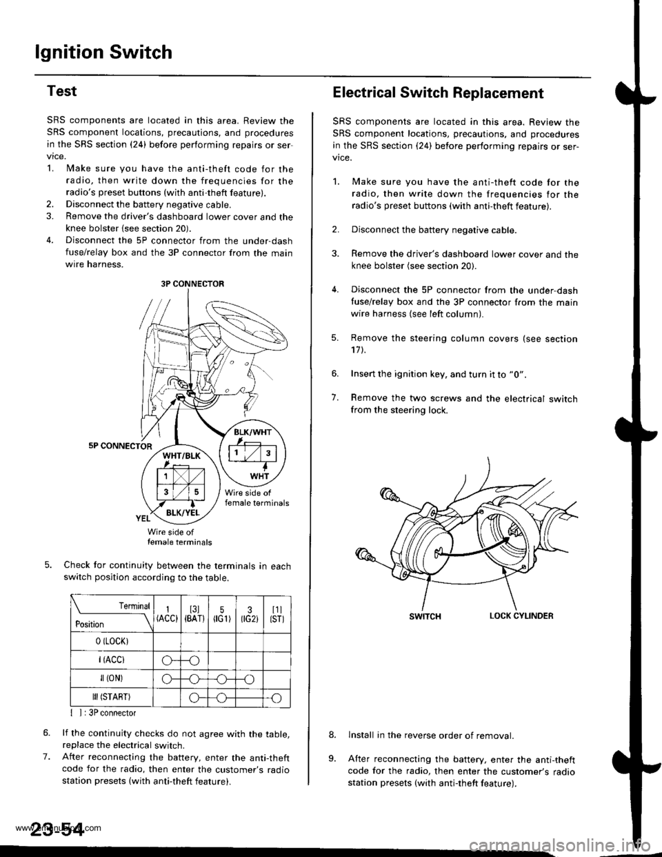
SRS components are located in this area. Review the
SRS component locations, precautions, and procedures
in the SRS section {24} before performing repairs or ser
vtce.
L lMake sure you have the anti-theft code for the
radio, then write down the frequencies for theradio's preset buttons (wilh anti-theft feature).
2. Disconnect the battery negative cable.
3. Remove the driver's dashboard lower cover and the
knee bolster {see section 20).
4. Disconnect the 5P connector from the under-dash
fuse/relay box and the 3P connector from the main
wtre narness,
5P CONNECTOR
Wire side oftemale terminals
Check tor continuity between the terminals in eachswitch position according to the table.
rernrnal
ros[ron \
I(ACC)I3l{BAT}5flG1)30G2iI1llsrl
0 (LocK)
r(Acclo--o
fl (oN)G_o
III (START)o--.o
7.
{ I | 3P connector
lf the continuity checks do not agree with the table,replace the electrical switch.
After reconnecting the battery, enter the anti-theftcode for the radio, then enter the customer's radio
station presets (with anti-theft feature).
23-54
3P CONNECTOR
Electrical Switch Replacement
SRS components are located in this area. Review the
SRS component locations, precautions, and procedures
in the SRS section {24) before performing repairs or ser-vice.
1. Make sure you have the anti-thett code for the
radio, then write down the frequencies for the
radio's preset buttons (with anti-theft feature).
2. Disconnect the battery negative cable.
3. Remove the driver's dashboard lower cover and the
knee bolster (see section 20).
4. Disconnect the 5P connector from the under,dash
tuse/relay box and the 3P connector f.om the main
wire harness {see left column).
7.
Remove the steering column covers (see section'17 t.
Insert the ignition key, and turn it to "0".
Remove the two screws and the electrical switchfrom the steering lock,
swrTcHLOCK CYLINDER
lnstall in the reverse order of removal.
After reconnecting the battery, enter the anti-theftcode for the radio, then enter the customer's radiostation presets (with antj-theft feature).
9.
www.emanualpro.com
Page 1215 of 1395
Gauge Assembly
Component Location Index
SRS components are located in this area. Review the SRS component locations, precautions, and procedures in the SRS
section {24} before performing repairs or service.
I x 1.25 mm24 N.m {2.4
VEHICLE SPEED SENSOF {VSS'Troubleshooting, page 23-62
GAUGE ASSEMBLYGau ge/lndicator/TerminalLocation Index, page 23-56Bulb Locations, page 23-57Removal, page 23-61
J-
FUEL GAUGE SENDING UNITSee section 1 l
PARKING BRAKE SWITCH
COOLANT TEMPERATURE GAUGESENDING UNITBRAKE FLUID LEVEL SWITCH
ENGINE OIL PRESSURE SWITCH
www.emanualpro.com
Page 1220 of 1395
Gauge Assembly
Circuit Diagram (cont'd)
GAUGE ASSEMBLY
REARCEILINGLIGHT
TAILGATELATCHswtTcH
rCLOSED I Glass open ItoPEN : Glass closed I
fCLoSED rTailsate open II0PEN iTailsateclosed.J
23-60
BLK
T
G552tlsA)-
AI Jl
I SRAKE FLUIOI LEVET SWITCHI fCLOSED . Floal down)
lLoPEN . Floal up J
BLK
+
G401G402
ABSCONTROLUNIT
PREVIOUSPAGE
a1
\J
BRAKESYSTEMLIGHTl1.4Wl
\
./
SEATBELTREMINDERLIGHT(1.4W)
\/'
7\
\
TAILGATEINDICATORLIGHT{1.4W}
Gnru;neo I f7 |
I i oo,,#, i| | RUI\N|NG 0GHTS I
I L__c_o!l!g_yI'__l
I t
rcanada)
l\
-l I
BED
RED
B6
'BLU
I INTEGRATEDI coNTRoLI UN|T
lv
IItt
r-IBLU
www.emanualpro.com
Page 1222 of 1395

Vehicle Speed Sensor (VSSI
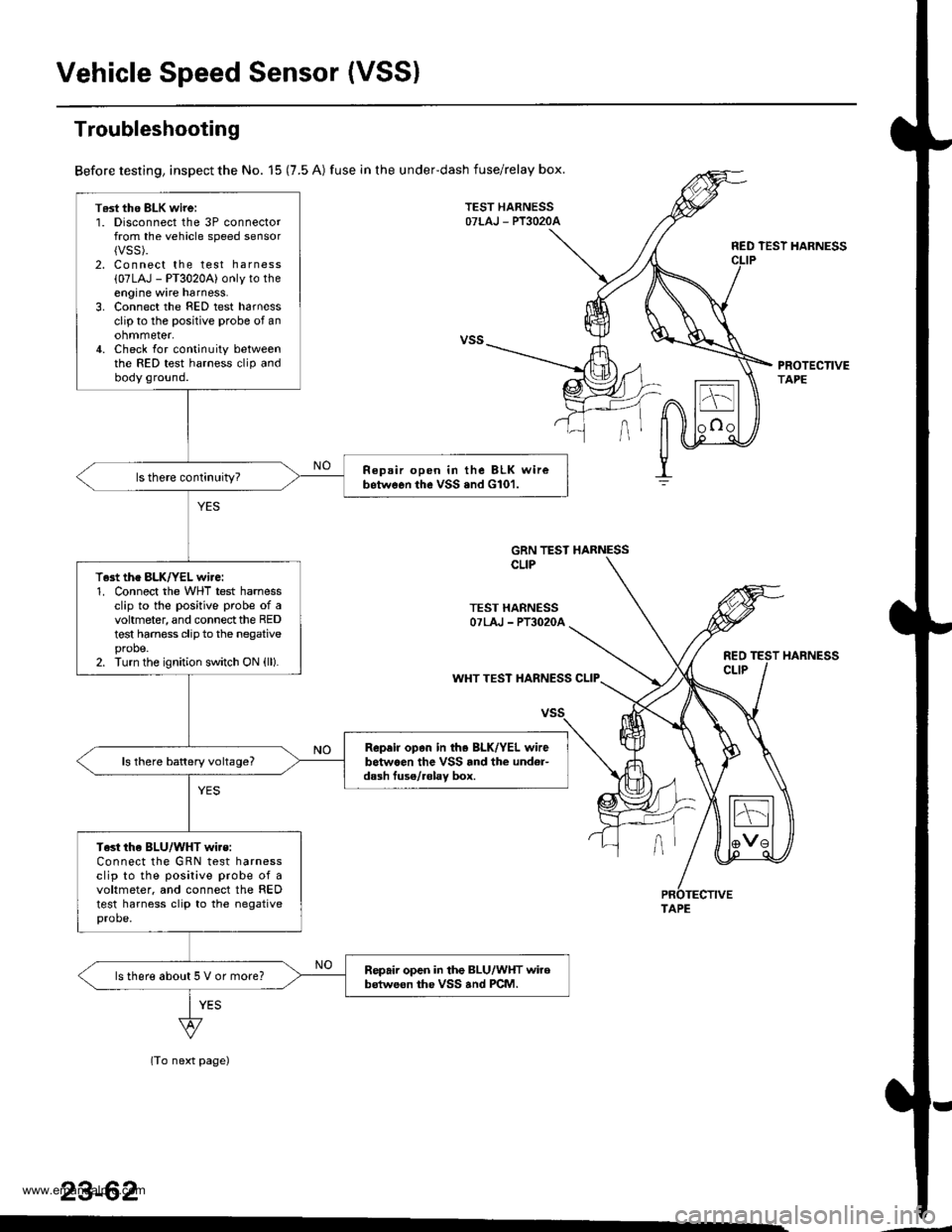
T6st tho BLK wirei1. Disconnect the 3P connectorfrom the vehicle speed sensor{VSS).2. Connect the test harness
{07LAJ - PT3020A) only to theengine wire harness.3. Connect the FED test harnessclip to the positive probe of anohmmeter,4. Check for continuity betweenthe RED test harness clip andbody ground.
Repair open in the BLK wirebetwGon the vSS .nd G101.
T.st the BLK/YEL wire:1. Connect the WHT test harnessclip to the positive probe of avohmeter, and connect the REDtest harness clip to the negativeprobe.2. Turn the ignition switch ON (ll).
Rep.ir op.n in th. BLK/YEL wirebetwaen the VSS rnd the und6r-dash fuse/.6lav box.ls there battery voltage?
Test the BLU/WHT wi.s:Connect the GRN test harnessclip to the posilive probe of avoltmeter. and connect the REDtest harness clip to the negativeprobe.
Repair open in the BLU/WHT wirobstweon the VSS and PCM.ls there about 5 V or more?
Troubleshooting
Before testing, inspect the No. 15 (7.5 A) fuse in the underdash fuse/relay box.
TEST HARNESSOTLAJ - PT3O2OA
RED TEST HARNESS
PROTECTIVETAPE
GRN TEST HARNESSCLIP
TEST HARNESSOTLAJ - PT3O2OA
REOCLIPWHT TEST HARNESS CLIP
(To next page)
23-62
HARNESS
TAPE
www.emanualpro.com