Page 495 of 1395

Transfer Assembly
Reassembly (cont'dl
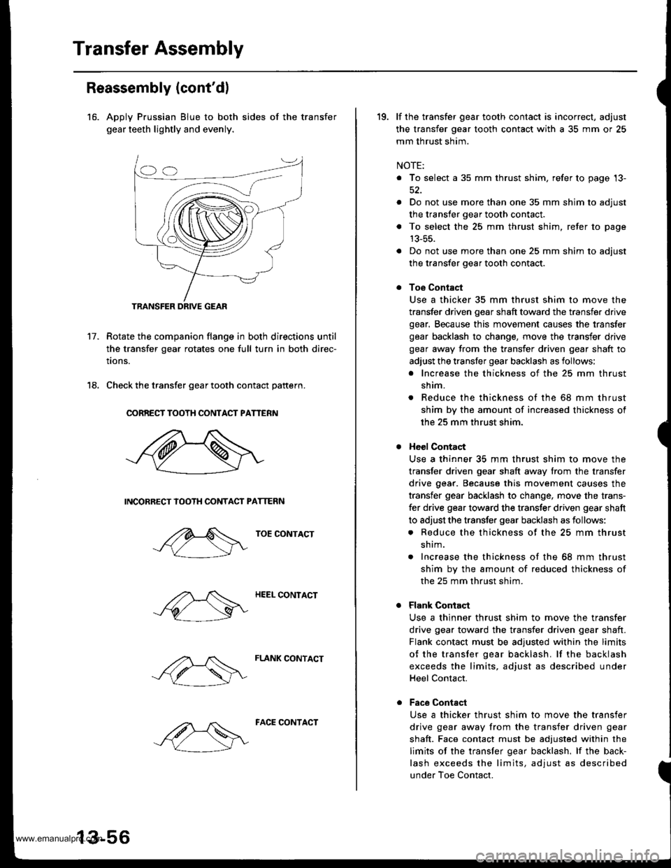
16. Apply Prussian Blue to both sides of the transfer
gear teeth lightly and evenly.
Rotate the companion flange in both directions until
the transfer gear rotates one full turn in both direc-
tions.
Check the transfer gear tooth contact pattern.
CORREST TOOTH CONTACT PATTERN
INCORRECT IOOTH CONTACT PATTERN
TOE CONTACT
HEEL CONTACT
FLANK CONTACT
17.
18.
TRANSFER DRIVE GEAR
13-56
FACE CONTACT
19. lf the transfer gear tooth contact is incorrect, adjust
the transfer gear tooth contact with a 35 mm or 25
mm thrust shim.
NOTE:
. To select a 35 mm thrust shim, refer to page '13-
. Do not use more than one 35 mm shim to adjust
the transfer gear tooth contact.
. To select the 25 mm thrust shim, refer to page
13-55.
a Do not use more than one 25 mm shim to adjust
the transfer gear tooth contact.
Toe Contact
Use a thicker 35 mm thrust shim to move the
transfer driven gear shaft toward the transfer drive
gear. Because this movement causes the transfer
gear backlash to change, move the transfer drive
gear away from the transfer driven gear shaft to
adjust the transfer gear backlash as iollows;
. Increase the thickness of the 25 mm thrust
shim.
. Reduce the thickness of the 68 mm thrust
shim bv the amount of increased thickness of
the 25 mm thrust shim.
Heol Contact
Use a thinner 35 mm thrust shim to move the
transfer driven gear shaft away from the transfer
drive gear. Because this movement causes the
transfer gear backlash to change, move the trans-
fer drive gear toward the transfer driven gear shaft
to adjust the transfer gear backlash as follows:
. Reduce the thickness of the 25 mm thrust
sh im.
a Increase the thickness of the 68 mm thrust
shim by the amount of reduced thickness of
the 25 mm thrust shim.
Flank Contact
Use a thinner thrust shim to move the transfer
drive gear toward the transfer driven gear shaft.
Flank contact must be adtusted within the limits
of the transfer gear backlash. lf the backlash
exceeds the limits, adjust as described under
Heel Contact.
Face Contsct
Use a thicker thrust shim to move the transfer
drive gear away from the transfer driven gear
shaft. Face contact must be adjusted within the
limits of the transjer gear backlash. lf the back-
lash exceeds the limits, adjust as described
under Toe Contact.
www.emanualpro.com
Page 496 of 1395

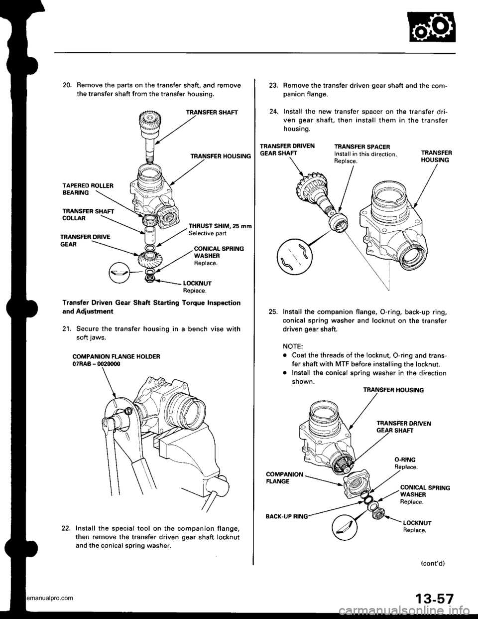
20. Remove the parts on the transfer shaft, and remove
the transfer shatt from the transfer housinq.
TRANSFER SHAFT
TRANSFER HOUSING
TAPERED ROLLERBEARING
TRANSFER SHAFTCOLLAR
TMNSFER DRIVEGEAR
THRUST SHIM, 25 mmSelective part
CONICAL SPRINGWASHERReplace.
LOCKNUTReplace.
Transter Driven Gear Shaft Starting Torque Inspection
and Adlustment
21. Secure the transfer housing in a bench vise with
soft iaws.
Install the special tool on the companion flang€,
then remove the transfer driven gear shaft locknut
and the conical spring washer.
COMPANION FLANGE HOLDER
22.
BACK.UP
Remove the transter driven gear shaft and the com-
panion flange.
Install the new transfer spacer on the transfer dri-
ven gear shaft, then install them in the transfer
housing.
TRANSFER DRIVENGEAR SHAFTTRANSFER SPACERInstall in this direction.TRANSFER
25.Install the companion flange, O-ring, back-up ring,
conical spring washer and locknut on the transfer
driven gear shaft.
NOTE:
. Coat the threads of the locknut, O-ring and trans-
fer shaft with MTF before installing the locknut.
. Install the conical spring washer in the direction
shown.
TRANSFER HOUSING
O.RING
COMPANIONFLANGECONICAL SPRINGWASHERReplace.
LOCKNUTReplace.
(cont'd)
13-57
www.emanualpro.com
Page 497 of 1395

Transfer Assembly
Reassembly (cont'dl
26. Secure the transfer housing in a bench vise with
soft jaws.
COMPANION FLANGE HOLDER07RAB - 002tD00
27. Install the special tool on the companion flange.
then tighten the transfer driven gear shaft locknut
while measuring the starting torque of the transfer
driven gear shaft.
STARTING TOROUE:
0.98 - 1.39 N.m
{10.0 - 1i1.2 kgf.cm, 8.68 - 12.3 lbf in}
TIGHTENING TOROUE:
132 - 216 N.m
(13.5 - 22.0 kgf.m, 97.6 - 159 lbf.ft)
NOTE:
. Rotate the companion flange several times to
seat the tapered roller bearing, then measure the
startrng torque.
. lf the starting torque exceeds 1.39 N.m (14.2
kgf.cm, 12.3 lbf.in), .eplace the transfer spacer
and reassemble the parts. Do not adjust the
torque with the locknut loose.
. lf the tightening torque exceeds 216 N.m (22.0
kgf.m, 159 lbf'ft), replace the transfer spacer and
reassemble the parts.
. Write down the measurement of the starting
torque: it is used to measure the total starting
torque.
28. Stake the locknut into the transfer driven oear shaft
using a 3.5 mm punch.
0.7 - 1.2 mm(0.03 - 0.05 inl
Point to bestaked.
Install the transfer shaft assemblv in the transfer
housing, then install the tapered roller bearing,
transfer shaft collar, 25 mm thrust shim, transfer
drive gear, conical spring washer, and transfer shaft
locknut on the transfer shaft.
NOTE:
. Coat the threads of the locknut and transfer shaft
with MTF before installing the locknut.
. lnstall the conical spring washer in the direction
snown.
TMNSFER SHAFTASSEMBLY
TRANSFER HOUSING
TAPERED ROLLERBEARING
TRANSFER SHAFTCOLLAR
TRANSFER DRIVEGEAR
PUNCH3.0-3.5 mm10.12 - 0.1a inl
THRUST SHIM, 25 mmSelective part
CONICAL SPRINGWASHEBReplace.
LOCKNUTReplace.
29.
www.emanualpro.com
Page 498 of 1395
30. Hold the transfer shaft with a 14 mm Allen wrench
clamDed in a bench vise.
NOTE: The locknut has left-hand threads.
TOROUE: 118 N.m (12.0 kgt'm,86.8 lbf'ft)
31. Stake the locknut on the transfer shaft using a 3.5
mm Dunch.
PUNCH3.0 - 3.5 mm{0.12 - 0.14 inl
14 mm ALLEN WRENCH
Totsl Starting Torquo Inspoction and Adiustment
32. Temoorarilv install transfer cover A without the O-
ring.
TRANSFER HOUSING
TRANSFER COVER A
oEl
€lE/Ehvc/E\\g8 x 1 .25 mm24 N.m (2.4 kg{ m, 17 lbtftl
5t.Secure the transfer housing in a bench vise with
soft jaws. then rotate the companion flange several
times to fit the tapered roller bearing,
TOROUE WR€NCH
34. Measure the total starting torque.
TOTAL STARNNG TOROUE:
1.70 - 2.08 N.m 117.3 - 21.2 kgf.cm, 15.0 - 18.i1 lbf inl
+ Transter Driven Gear Shaft Starting Torque Value
(wrot€ down in step 27).
(cont'd)
13-59
www.emanualpro.com
Page 499 of 1395

Transfer Assembly
Reassembly (cont'd)
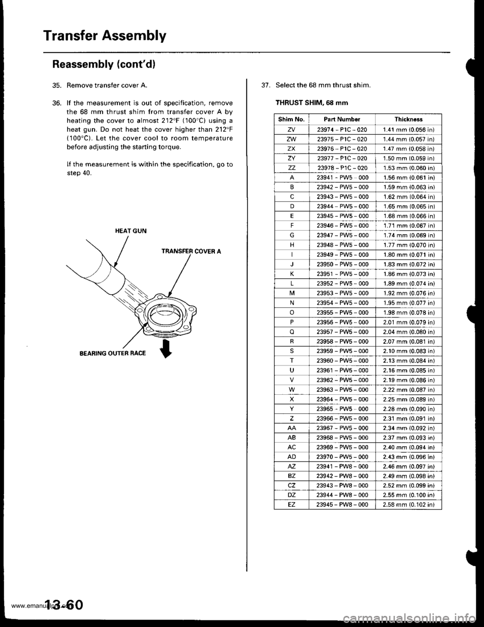
Remove transfer cover A.
lf the measurement is out of specification, remove
the 68 mm thrust shim from transfer cover A by
heating the cover to almost 212'F (100'C) using a
heat gun. Do not heat the cover higher than 212F
(100"C). Let the cover cool to room temperature
before adjusting the starting torque.
lI the measurement is within the specification, go to
step 40.
COVER A
BEARING OUTER RACE
35.
36.
HEAT GUN
13-60
37. Select the 68 mm thrust shim.
THRUST SHIM, 68 mm
Shim No.Part NumberThickne3s
zv23914-P1C-0201.41 mm (0.056 in)
zw23975-P1C-020'1.44 mm 10.057 in)
zx23916 PlC -020'1.47 mm (0.058 in)
ZI23917 -P1C-O201.50 mm (0.059 in)
zz23978-PlC-0201.53 mm (0.060 in)
23941 - PW5 0001.56 mm {0.061 in)
23942-PWs-0001.59 mm (0.063 in)
c23943-PW5-000't.62 mm (0.064 in)
D23944 PW5 - 0001.65 mm (0.065 in)
E23945-PWs-0001.68 mm (0.066 in)
F23946-PW5-0001.71 mm 10.067 in)
G23947-PW5-000'1.74 mm 10.069 in)
23948-PWs-0001.77 mm (0.070 in)
23949-PWs-0001.80 mm (0.071 in)
239s0-PW5-0001.83 mm (0.072 in)
K23951 - PW5 - 0001.86 mm (0.073 in)
L23952-PWs-0001.89 mm {0.074 in)
239s3-PWs-0001.92 mm {0.076 ini
N23954-PW5-0001.95 mm (0.077 in)
o23955-PW5-0001.98 mm (0.078 in)
P23956 - PW5 , 0002.01 mm (0.079 in)
o23957-PWs-0002.04 mm (0.080 in)
R23958-PWs-0002.07 mm (0.081 in)
23959-PW5-0002.10 mm (0.083 in)
T23960-PW5-0002.13 mm (0.084 in)
U23961 - PW5 - 0002.16 mm (0.085 in)
23962-PW5-0002.19 mm (0.086n)
23963-PWs-0002.22 mm (0.087n)
X23964-PWs-0002.25 mm (0.089n)
23965,PWs-0002.28 mm 10.090n)
23966-PW5-0002.31 mm {0.091 in)
23967-PWs-0002.34 mm (0.092 in)
AB23968-PWs-0002.37 mm (0.093 in)
AC23969-PWs-0002.40 mm {0.094 in}
AD23970-PW5-0002.43 mm (0.096 in)
M23941 - PW8 - 0002.46 mm {0.097 'n}
BZ23942-PW8-0002.49 mm (0.098 in)
cz23943-PW8-0002.52 mm {0.099 ini
DZ23944-PW8-0002.55 mm (0.100 in)
EZ23945-PW8-0002.58 mm (0.102 ini
www.emanualpro.com
Page 500 of 1395
38. Install the 68 mm thrust shim using the special
tools.
DRIVER077€ - 001(xno
THRUST S1{IM,68 mmSelective part
BEARING OUTER BACE
ATTACHMENT.62x68mm077a6 - (x)10500
39.After replacing the 68 mm thrust shim, recheck and
make sure the total starting torque is within the
soecification.
40. Coat the new O-rings with MTF, install them on
transfer covers A and B, then install the covers on
the transfer housing.
6x1.0mm12 N.m 11.2 kgf.m,8.7 tbt.ft)TRANSFER COVER B
TRANSFER
O.RINGReplace.
O.BINGReplace.
TRANSFERCOVER A
8 r 1.25 mm2,r N.m (2.4 kgl.m. 17 lbtft)
13-61
www.emanualpro.com
Page 510 of 1395

22. Turn the select lever and shift arm shaft counter-
clockwise, then insert the shift arm shaft.
INTERLOCK EOLT39 N.m (4.0 kqt ft, 29 lbf ft)SELECT ARM
SHIFT ARM A
Align the shift arm A groove and select arm finger
by turn the shift arm shaft and select lever clock-
wise. then installthe shift arm shaft assembly.
Apply liquid gasket (P/N 08718 - 0001 or 08718 -
OO03) to the threads, then install the interlock bolt'
Apply liquid gasket to the surface of the shift arm
cover as snown.
Note these items:
. Use liquid gasket (P/N 08718 - 0001 or 08718 -
0003).
. Remove the dirtv oilfrom the sealing surface.
. Seal the entire circumference of the bolt holes to
prevent oil leakage.
. lf 20 minutes have passed after applying liquid
gasket. reapply it and assemble the housings.
a Allow it to cure at least 20 minutes after assem-
bly betore filling the transmission with MTF.
23.
-->.-
(
SHIFT ARM SHAFT
SHIFT ARM COVER ASSEMBLY
10 x 12 mft DOWEL PIN
t1
26. Install the shift arm cover assembly.
I x 1.25 mm27 N m 12.8 kgt m,20 lbf'ft)
Install the transfer assemblY.
NOTE: Lubricate MTF to the O-ring and contact
areas.
10 x 1.25 mm44 N.m 14.5 kgf.m, 33 lbl.ftl
13-71
www.emanualpro.com
Page 513 of 1395
Transmission Assembly
Installation (cont'dl
13. Installthe balljoints onto the lower arms.
DAMPER PINCH BOLT10 x 1.25 mm43 N.m {a.a kgf.m,32 rbfft)
SELF.LOCKING NUT'12 x 1.25 |nm6il N'm 16.5 kgtin, 47 lbtftlReolace.
Replace.
14.
PROPELI"ER SHAFT
13-74
12 x 1.25 mm,19 - 59 N.m(5.0 - 6.0 kgi.m, 36 - € lbfttl
Install the right damper fork bolt.
Install the propeller shaft to the transfer assembly
by aligning the reference marks.
E x 1.25 mr'|
15.
REFERENCE MARKS
32 N.m 13.3 kst m, 2a lbf.ftl
TRANSFER
Install the exhaust pipe A, then connect the heated
oxygen sensor (HO2S) connector.
GASKETSReplace.
HO2S CONNECTOR
10 x 1.25 mm5,1N.m 15.5 kgtm.() tbt filReplace.
SELF.LOCKING
SELF.LOCKING NUT8 x 1.25 mm16 N.rn 11.6 kg{.m,12lbtfr)Replace.
GASKETReplace.
8 x 1.25 rr|ln22 N.m (2.2 tgf.m, 16 lbl.ftlReplac6.
'17. Installthe guard bar and the splash shield.
SPLASH SHIEI.I)I x 1.25 mm24 N.m l2.a kgf.m.17 tbtft)GUARD BAR
6x1.0mm9.8 N.m (1.0 kgf.m, 7.2 lbf.ft)
www.emanualpro.com