Page 309 of 1395
![HONDA CR-V 2000 RD1-RD3 / 1.G Workshop Manual
The scan tool indicates Diagnostic Trouble Code (DTC) P0123: A high voltage problem in the Throttle Position
(TP) sensor circuit.
TP SENSOR 3P @]{NECTOR IC13O}
sG2(GnN/Br.XlvocrtYEt /8LU)
{GBIT/BLKI
HONDA CR-V 2000 RD1-RD3 / 1.G Workshop Manual
The scan tool indicates Diagnostic Trouble Code (DTC) P0123: A high voltage problem in the Throttle Position
(TP) sensor circuit.
TP SENSOR 3P @]{NECTOR IC13O}
sG2(GnN/Br.XlvocrtYEt /8LU)
{GBIT/BLKI](/manual-img/13/5778/w960_5778-308.png)
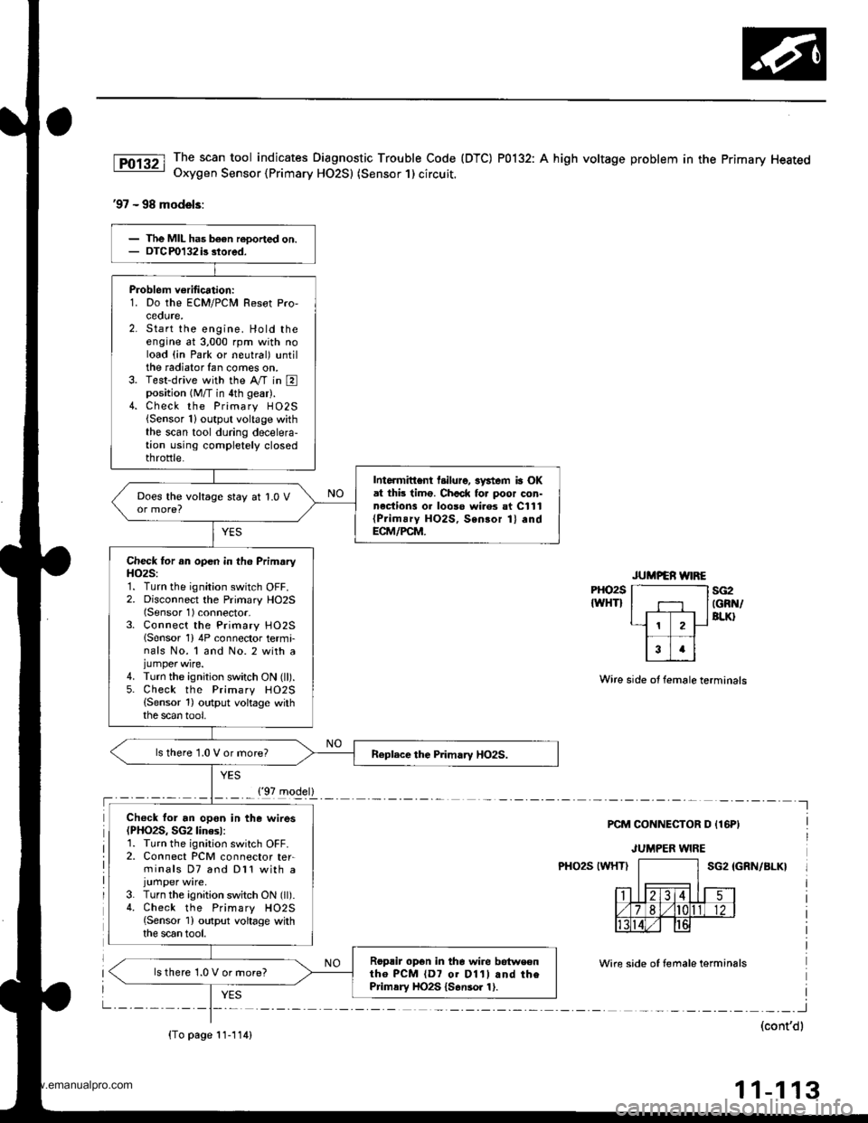
The scan tool indicates Diagnostic Trouble Code (DTC) P0123: A high voltage problem in the Throttle Position
(TP) sensor circuit.
TP SENSOR 3P @]{NECTOR IC13O}
sG2(GnN/Br.XlvocrtYEt /8LU)
{GBIT/BLKI
(cont'd)
11-107
Wiro side of fom.le terminals
PCM CON'{ECTOF D I16PI
Wire side ot female terhinals
The MIL hlr br€n r.9ort.d on.DTC P0123 ir stored.
Pioblom vorificltion:1. Start the ongin6. Hold th€ongine at 3,000 rpm with noload {in Park or neutral) untilth6 radiator fan comes on.then turn the ignition switchOFF,2. Turn the ignition switch ON (ll).
3. Check the throttle position
with the scan tool.
Intarmittant tailuro, ryrtern b OKat this timo. Chock lor poor con-nections or loo3o wir€3 at C130
ITP 3orcorl .nd at tho ECM/FCM.
ls there spprox. 1oyo when thothrottle is Iully closed andapprox.90% when the throttleis tully open€d?
Choct toJ an opcn in th6 TP s6n-3t']:1. Turn the ignition switch OFF.2. Disconnect the TP sensor 3Pconnectol,3. Turn the ignition switch ON (ll).
4. At the wir6 harnoss side, mea-suro voltage betweon thg TPsensor 3P connector t€rminalsNo. 1 and No.3.
ls there approx.5 V?
Chack for an oDan in tha wira(SG2 linel:M6asu16 voltage b6tween PCMconn€ctor terminals Dl0 and D'! 1.
R.pai. opcn in tha wira botwcontho PcM {o111 rnd the TP 3en-3('t,
ls there approx. 5 V?
('97 model)
(To page 11-108)
www.emanualpro.com
Page 310 of 1395
PGM-FI System
(From page 11-107)
Check lor an open in the wirc(SG2line):
Measure voltage between ECM/PCM connector C (31P) terminalsC18 and C28.
Ropair open in th€ wire betweonrhe ECM/PCM (Cl81 .nd the TP56nSOl,
ls there approx. 5 V?
Substitute a known-good ECM/PCM and rocheck. lf pre3cribedvoltago is now avaibble, replacetho origin.l ECM/PCM,
Throttle Position (TP) Sensor (cont'dl
ECM/PCM CONNECTOR C {31PI
Wire side of temale terminals
1 1-108
www.emanualpro.com
Page 312 of 1395

PGM-FI System
Primary Heated Oxygen Sensor (Primary HO2S) (Sensor 1)
The Heated Oxygen Sensors (HO2S) detect the oxygen content in the exhaust gas and signal the ECM/PCM. In operation,
the ECM/PCM receives the signals from the sensor and varies the duration during which fuel is iniected. To stabilize the
sensor's output, the sensor has an internal heater. The Primary HO2S (Sensor 1) is installed in exhaust pipe A.
HO2S:
ztRcoNtAEI.IMENT
s€NsoRTERMINALSVOLTAGE IVI
HEATEBTERMINALS
The scan tool indicates Diagnostic Trouble Code (DTC) P0131: A low voltage
Oxygen Sensor (HO2S) {Sensor 1} circuit,
RICH - AIR. . LEANFUELNATO
problem in the Primary Heated
37 - 98 models:
HEATER
The MIL has been reoorted on.DTC P0131 is stoied.
Problem verification:1. Do the ECM/PCM Reset Pro-ceoure.Start the engine. Hold theengine at 3,000 rpm with noload (in Park or neutral) untilthe radiator fan comes on.Test-drive with the A/T in Eposition (M/T in 4th gear)Check the Primary HO2S{Sensor 1} output voltage withthe scan tool during accelera-tion using wide open throttle.
Intermittent f.ilure, system is OKat this time. Check fo. poor con-nections or loose wirer at C111(Primary HO2S, SeGor 1) and atrh€ ECM/FCM.
Check the fuel pressure (see page
11-178).
Repair the fuel supply system.
{To page 11'111}
1 1-1 10
www.emanualpro.com
Page 315 of 1395

The scan tool indicates Diagnostic Trouble Code (DTC) P0132: A high voltage problem in the Primary HeatedOxygen Sensor {Primary HO2S) (Sensor 1) circuit.
'97 - 98 models:
PHO2S
IWHTIsG2IGRN/BLK}
Wire side ot female terminals
PCM CONNECTOR D {16PI
JUMPER WIRE
PHO2S IWHTISG2 IGRN/BLK}
Wire side of temale terminals
I
(cont'dl
11-113
Problem verification:1. Do the ECM/PCM Resot Pro,ceoute,2. Start the engine. Hold theengine at 3,000 rpm with noload (in Park or neutral) untilthe radiator fan comes on.3. Test-drive with the Ay'T in Eposition (M/T in 4th gear).4. Check the Primary H02S{Sensor 1}output voltage withthe scan tool during decelera-tion using completely closedthrottle.
Intormittent l.ilure, 3ystem ia OKat thb timo. Chcck fo. poor con-nections 01 looso wi.es at C111{Prim!ry HO2S, Sensor 1} andECM/PCM.
Does the voltage stay at 1.0 V
Check for an open in th6 PrimaryH()2S:1. Turn the ignition switch OFF.2. Disconnect the Primary HO2S(Sensor 1) connector-3. Connect the Primary HO25lSensor 1) 4P connector termi-nals No. 1 and No. 2 with ajumper wire.4. Turn the ignition switch ON (ll).5. Check the Primary HO2S(Sensor 1) output voltage withthe scan tool,
ls there 1.0 V or more?
Ch€ck for an opon in the wires(PHO2S, SG2linesl:1. Turn the ignition switch OFF.2. Connect PCM connector ter-minals D7 and Dl1 with a
3. Turn the ignition switch ON (ll).4. Check the Primary HO2S{Sensor 1) output voltage withthe scan tool.
Roprir opon in the wire betweontho PCM {D7 01 D11l and thePrimsry HO2S {S6nsor 1).
ls there 1.0 V or more?
{'97 model}
{To page 11-114)
www.emanualpro.com
Page 318 of 1395

PGM-FI System
Primary Heated Oxygen Sensor (Primary HO2S) lSensor 1) (cont'd)
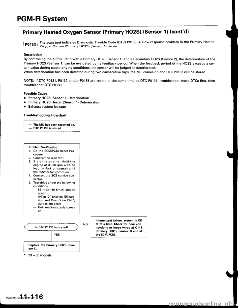
tFO133 lhe scan tool indicates Diagnostic Trouble Code (DTC) P0133: A slow response problem in the Primary Heated: Oxysen Sensor (Primarv HO2S (Sensor 1) circuit.
Description
By controlling the airlfuel ratio with a Primary HO2S (Sensor 1) and a Secondary HO2S (Sensor 2), the deterioration of the
Primary HO2S (Sensor 1) can be evaluated by its feedback period. When the feedback period of the HO2S exceeds a cer
tain value during stable driving conditions, the sensor will be judged as deteriorated.
When deterioration has been detected during two consecutive trips, the MIL comes on and DTC P0133 will be stored.
NOTE: lf DTC P0131, P0132 and/or P0135 are stored at the same time as DTC P0133. troubleshoot those DTCS first, then
troubleshoot DTC P0133.
Possible Cause
. Primary HO2S (Sensor 1) Deterioration
. Primary HO2S Heater (Sensor 1) Deterioration
. Exhaust system leakage
Troubleshooting Flowchart
- The MIL has b6€n reoorted on.- DTC P0133 is stored.
Problem Verilication:'1. Do the ECM/PCM Reset Procedure.2. Connect the scan tool.3. Start the engine. Hold theengine at 3,000 rpm with noload lin Park or neutrali untilthe radiator fan comes on.4. Connect the SCS service connector.5. Test-drive under the followingcondations,55 mph (89 km/h) steadyspeed- M in @ position (E position and Over Drive ON)*,(M/T in sth gear)- Until readiness code comes
Intermittent failure, system is OKat this time. Check tor poor con-nections or loose wires at C111(Primary HO2S, Sensor 1) and althe ECM/PCM.
Replace the Primary HO2S {Sen-sor 11.
1 1-1 16
www.emanualpro.com
Page 333 of 1395

tro-rsl
1Tffi61
tF136t
fPfa6r-1
tF138tl
I-Pi382l
Crankshaft Position/Top Dead Genter/Gylinder Position (CKP/TDC/CYPI Sensor
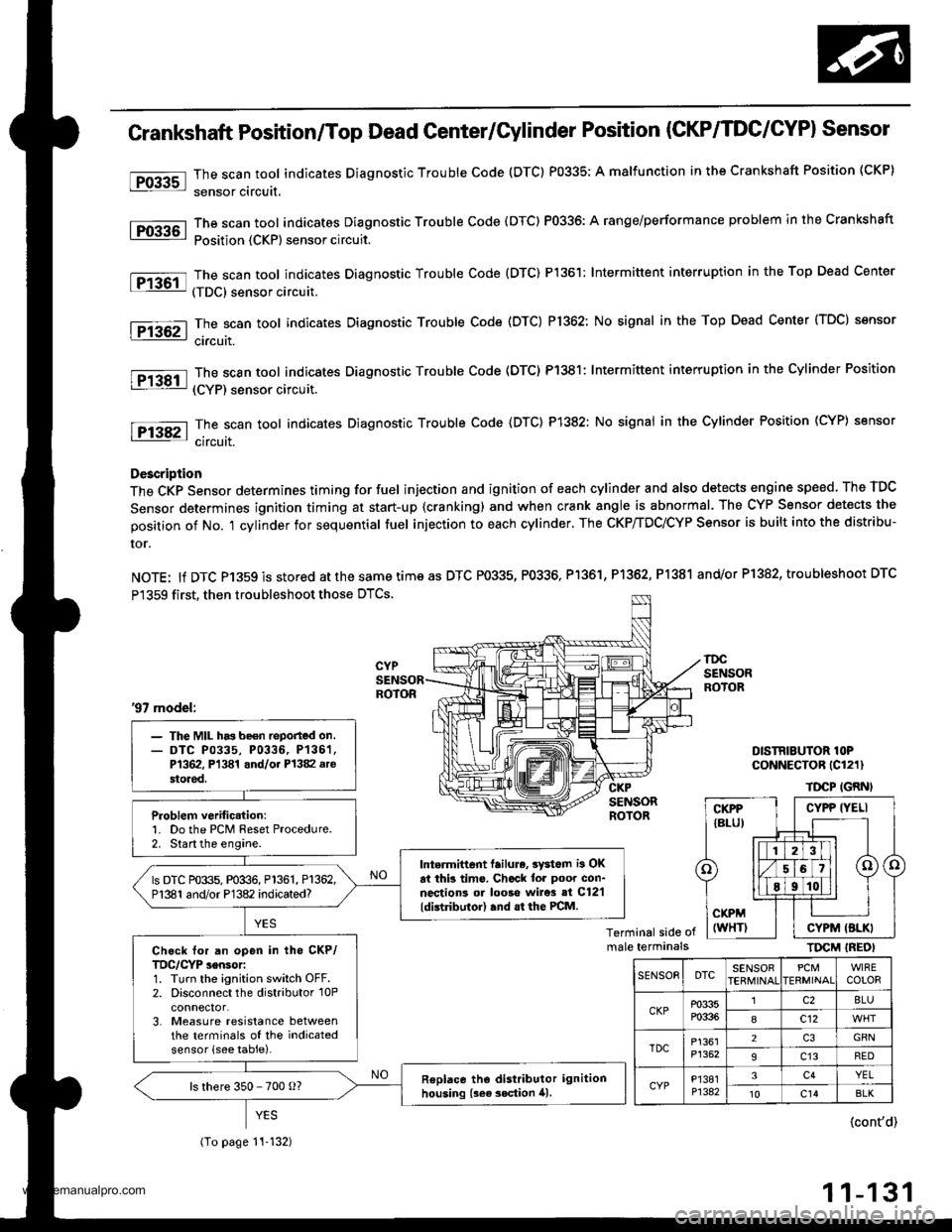
The scan tool indicates Diagnostic Trouble Code (DTC) P0335; A malfunction in the Crankshaft Position (CKP)
sensor circuit,
The scan tool indicates Diagnostic Trouble Code (DTC) P0336: A range/performance problem in the Crankshaft
Position {CKP) sensor circuit.
The scan tool indicates Diagnostic Trouble Code {DTC) P1361: Intermittent interruption in the Top Dead Center
(TDC) sensor circuit.
The scan tool indicates Diagnostic Trouble Code (DTC) P1362: No signal in the Top Dead Center (TDC) sensor
ci.cuit.
The scan tool indicates Diagnostic Trouble Code (DTC) P1381: Intermittent interruption in the Cylinder Position
(CYP) sensor circuit.
The scan toot indicates Diagnostic Trouble Code {DTC) P1382: No signal in the Cylinder Position (CYP} sensor
circuit.
Description
The CKP Sensor determines timing for fuel injection and ignition of each cylinder and also detects engine speed. The TDC
Sensor determines ignition timing at start-up {cranking) and when crank angle is abnormal. The CYP Sensor detects the
position of No. 't cylinder for sequential fuel injection to each cylinder. The CKP/TDC/CYP Sensor is built into the distribu-
ror.
NOTE: lf DTC P1359 is stored atthesametimeas DTC P0335, P0336, Pl361, P1362, P1381 and/or P1382, troubleshoot DTC
P1359 first, then troubleshoot those DTCS.
DISTRIBUTOR lOPCoNNECTOR (Cl211
TDCP IGRNI
Terminal side ofmale terminalsTIrcM IREOI
'97 model:
- The MIL has be€n reported on.- DTC P0335, P0336, P136'�1,P1362, Pl341 and/oi P1382 arestored.
Problem verific.tion:1. Do the PCM Reset Procedure.2. Start the engine.
Intermittent lailure, 3yd6m i3 OKat thb tims. Chcck tor poor con-nections ol looso wire3 si C12'l
ldistributor) .nd .t the PCM.
ls DTC P0335, P0336, P1361, P1362,P1381 and/or P1382 indicated?
Ch.ck for an open in tho CKP/TDC/CYP sensor:1. Turn the ignition switch OFF.2. Disconnect the distributor 10Pconnector.3. Measure resistance betweenthe terminals of the indicatedsensor (see table).
Replace tho distributor ignitionhousing {sea 3ection 41.ls there 350 - 700 o?
(To page 11-132)
CYPP IYELI
CYPM (BLKI
SENSOEDTCSENSOBPCMERMINAIWIRECOLOR
CKPP0335P0336
lc28LU
8c12
TDCP1361P1352
2GRN
9c13RED
CYPP'�I381P1342
3c4YEL't0c14BLK
{cont'd)
11-131
www.emanualpro.com
Page 334 of 1395

PGM-FI System
Grankshaft Position/Top Dead Center/Cylinder Position (CKP/TDC/CYPI
Sensor (cont'd)
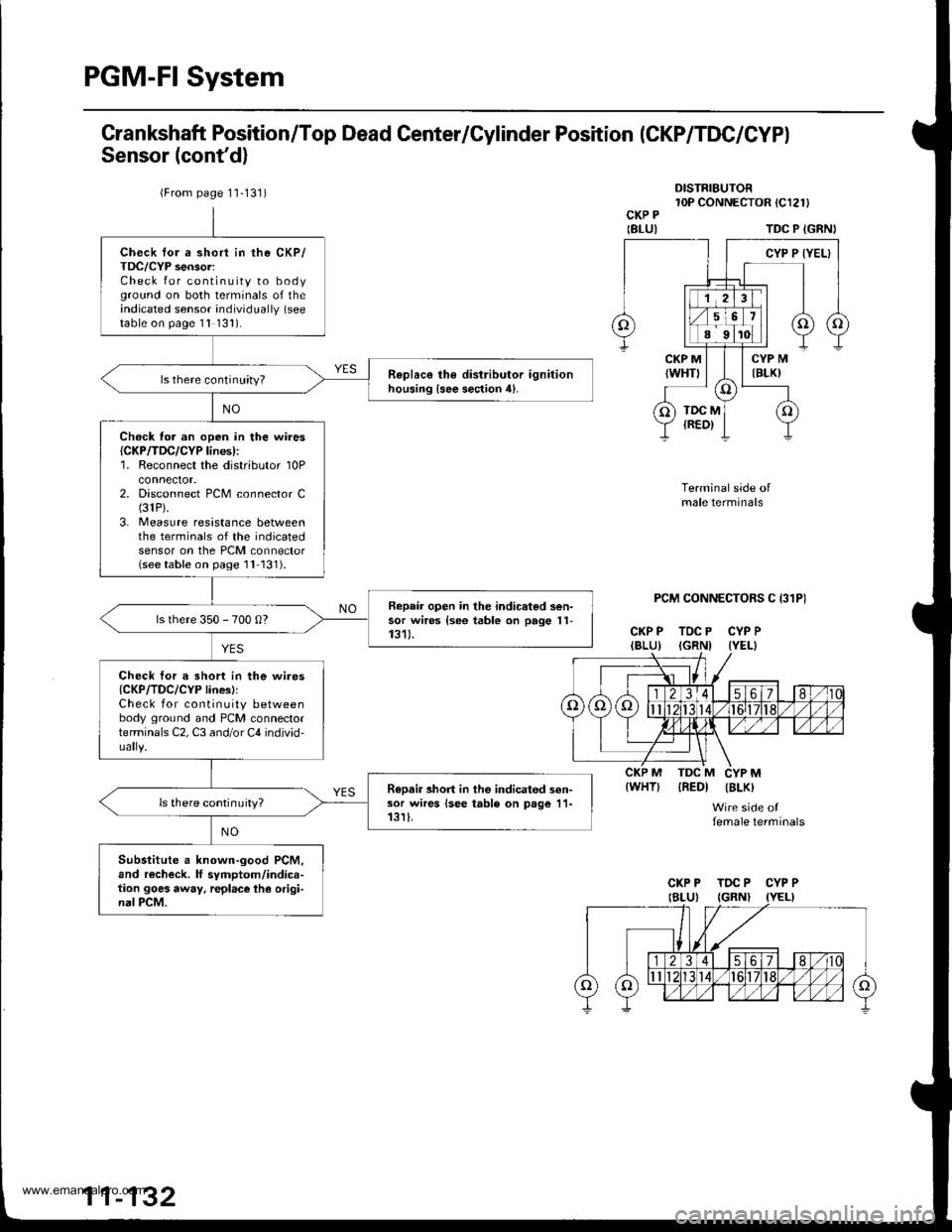
DISTRIBUTOR10P CONNECTOR tCl2l)CKP P
IBLUITDC P {GRNI
PCM CONNECTORS C I31P)
CKP P TDC P CYP PIBLU) IGRNI IYEL}
Terminal side ofmale terminals
IREDI IBLK)
Wire side offemale terminals
{WHT)
{From page 1'1-131)
Check for a short in the CKP/TDC/CYP sensor:Check for continuity to bodyground on both terminals of theindicated sensor individually (see
table on page 1l 131).
R€plac€ the distributor ignitionhousing {see section 4}.ls there continuity?
Ch€ck fo. an open in the wires{CKP/TDC/CYP lines):'1. Reconnect the distributor 10Pconnector.2. Disconnect PCM connector C(31P).
3. Measure resistance betweenthe terminals of the indicatedsensor on the PCM connectorlseetable on page 1l 131).
Repair open in the indicated sen-sor wires {se6 table on page 11-131).ls there 350 - 700 0?
Check tor a short in the wires{CKP/TDC/CYP linesllCheck for continuity betweenbody ground and PCM connectorterminals C2, C3 and/or C4 individ-
R€Dair short in the indicatod sen-sor wires lsee table on page 11-13rI.ls there continuity?
Substitute a known-good PCM,and recheck. lf symptom/indica-tion goes away, r€place lhe origi-nal PCM.
CKP P TDC P CYP P
www.emanualpro.com
Page 336 of 1395
PGM-FI System
Grankshaft Position/Top Dead Center/Cylinder Position (CKP/TDC/CYPI
Sensor {cont'd}
(From page 11 133)
ECM/PCM CONNECTOR C {3IPI
Wire side of female terminals
Chock lor r 3hon in tho wirerICKP/TDC/CYP lin6):Check for continuity betweenbody ground and ECM/PCM con-nector terminals C8, C20 and/orC29 individually.
Rep.ir lhort in ths indicated son-aor wiroa 136o table on prge 11-133).
Substituto r known-good ECM/PCM, and .6chock. tf 3ymptom/indication goe3 swey, replrcetho original ECM/PCM.
11-134
www.emanualpro.com