Page 395 of 1395
Intake Air System
System Description
The system supplies air for all engine needs. lt consists of the intake air pipe, Air Cleaner, intake air duct, Throttle Body
(TB), ldle Air Control (lAC) Valve, fast idle thermo valve, and intake manifold. A resonator in the intake air pipe provides
additional silencing as air is drawn into the system.
INTAKE MANIFOLD
YEL| - - Fiom PGM'FI
BLK T MAIN RELAY
IDLETHERMO
lJ- _iuo'u'j"'
INTAKEAIR DUCT
vaRtousSENSORS
FESONATON
THROTTLEBODY (TB)
1 1-193
www.emanualpro.com
Page 403 of 1395
Positive Grankcase Ventilation (PGVI System
Description
The Positive Crankcase Ventilation (PCV) svstem is
designed to prevent blow-by gas from escaping to the
atmosphere. The PCV valve contains a spring-loaded
plunger, When the engine starts, the plunger in the PCV
valve is lifted in proportion to intake manitold vacuum and
the blow-by gas is drawn directly into the intake manifold.
-: BLOW.BY VAPOR-: FRESH AIR
i/lAlrllFOLD
Inspoction
1. Check the PCV hoses and connections for leaks and
clogging.
'97 - 98 models:
'99 - (X) models:
BREATHERHOSE
(cont'd)
11-201
www.emanualpro.com
Page 404 of 1395
Emission Control System
Positive Crankcase Ventilation (PCV) System (cont'dl
2. At idle, make sure there is a clicking sound from the
PCV valve when the hose between the PCV valve
and intake manifold is lightly pinched with your fin-
gers or pliers.
'97 - 98 models:
'99 - 00 modelsi
lf there is no clicking sound, check the PCV valvegrocrmet for cracks or damage, lf the grommet is
OK, reDlace the PCV valve and recheck.
Gently pinch here.
Gently pinch here.
11-202
www.emanualpro.com
Page 405 of 1395

EVAP PURGE CONTROL SOLENOID VALVE DUTY CONTROLLED AFTER
STARTING ENGINE
ENGINE COOLANT TEMPERATURE ABOVE 154"F (68'C)
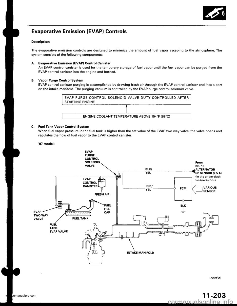
Evaporative Emission (EVAP) Controls
Description:
The evaporative emission controls are designed to minimize the amount of fuel vapor escaping to the atmosphere. The
system consists of the following components:
A. Evaporative Emission (EVAPI Control Canister
An EVAP control canister is used for the temporary storage of fuel vapor until the luel vapor can be purged from the
EVAP control canister into the enqine and burned.
B. Vapor Purge ConirolSystem
EVAP control canister purging is accomplished by drawing fresh air through the EVAP control canister and into a pon
on the intake manifold. The purging vacuum is controlled by the EVAP purge control solenoid valve.
C. Fuel Tank Vapor Control System
When fuel vapor pressure in the fuel tank is higher than the set value of the EVAP two way valve, the valve opens and
regulates the flow ot fuel vapor to the EVAP control canister.
'97 model:
EVAPPURGECONTROL
VALVEFromNo. 15BLK/ /ALTERNATORYEL I sP SENSOR r7.s At(in the under-dashfuse/relay box)
VARIOUSSENSORFEESH AIF
BLK
I
FUEI- TANK
(cont'd)
11-203
INTAKE MANIFOLD
www.emanualpro.com