Page 946 of 1395

Brake Hoses/Lines
Hose Replacement
CAUTION: Do not spill brak€ fluid on the vehicl€; it m8y
damage th€ paint; if brak€ lluid doos contact tho paint,
wash it off immediately with water.
NOTE:
. Before reassembling, check that all pans are free of
dust and other foreign particles.
. Replace parts with new ones whenever specified to
qo so,
Replace the brake hose ifthe hose is twisted, cracked.
or if it leaks.
Disconnect the brake hose from the brake line using
a 10 mm flare nut wrench.
'1.
FLARE NUTWRENCH(Commercially
available)
BRAKE HOSE
Remove and discard the brake hose cliD from the
brake hose.
Remove the banjo bolt, and disconnect the brake
hose from the calioer.
5. Remove the brake hose from the knuckle.
19-22
6. Install the brake hose on the knuckle first, then con-
nect the brake hose to the caliper with the banjo bolt
and new sealing washers.
6 mm HOSE BRACKETEOLTS9.8Nm(1.0 kgf.m,7 lbf.ftlBRAKE HOSE
BANJO BOLT34 N.m
13.5 kgf.m, 25 lbl.ftl
SEALING WASHERSHeplace.
7. Installthe brake hose on the upper brake hose bracket
with a new b.ake hose clip.
Replace.
BRAKE HOSE ARACKET
Connect the brake line to the brake hose.
After installing the brake hose, bleed the brake sys-
tem (see page '19-7).
Perform the following checks;
. Check the brake hose and line joint for leaks, and
tighten if necessary.
. Check the brake hoses for interference and twist-
Ing
1 tbtftl
F
)
/
8.
9.
www.emanualpro.com
Page 1207 of 1395

BLKG401
GroundWir€ ColorComponent or Circuits Grounded
ABS indicator circuit
ABS control unit
Ashtray light
A/T gear position indicator dimming circuit
Brake fluid level switch
Clock ('98 - 00 models)
Clutch inrerlock switch (M/T)
Clutch switch (Mff)
Cruise main switch
Cruise indicator circuit
Cruise control unit
Dash lights brightness controller
Data iink connector
Daytime running rights control unit (Canada)
Front accessary socket
Gauge and indicators
Heater control panel
lgnition key light control unit ('97 model)
lgnition key switch
Integrated control unit
Interlock control unit (Ay'T)
Parking pin switch {A,/T)
Power window relay
Rear accessary socket relay
Bear window defogger relay
Rear window wiper control unit ('97 model)
Service check connector
Spotlights
SRS indicator circuit
Turn signal/hazard relay
Windshield wiper motor
Windshield wiper/washer switch- plus everything grounded through G402
ABS control unit
Blower motor relay
Blower motor high relay
ELD unit (USA)
Power transistor- plus everything grounded through G401
BLKG402
{cont'd)
23-47
www.emanualpro.com
Page 1280 of 1395

Wipers/Washers
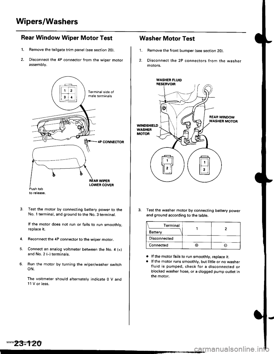
1.
Rear Window Wiper Motor Test
Remove the tailgate trim panel (see section 20),
Disconnect the 4P connector from the wiper motor
assembly.
4P CONNECTOR
WIPEBLOWER COVEnPush tabto release,
Test the motor by connecting battery power to theNo. I terminal, and ground to the No. 3 terminal.
lf the motor does not run or fails to run smoothly,replace it.
Reconnect the 4P connector to the wiper motor.
Connect an analog voltmeter between the No. 4 (+)
and No. 2 (-) terminals.
Run the motor by turning the wiper/washer switchoN.
The voltmeter should alternately indicate 0 V and11 V or less.
4.
5.
23-120
1.
Washer Motor Test
Remove the front bumper (see section 20).
Disconnect the 2P connectors from the washermolors,
REAR WINDOWWASHER MOTOR
Test the washer motor by connecting battery power
and ground according to the table.
lf the motor fails to run smoothly, replace it.lf the motor runs smoothly, but little or no washerfluid is pumped, check for a disconnected orblocked washer hose, or a clogged pump outlet inthe motor.
a
a
L_Iq'.r91
Battery
,l
Disconnected
Connected@
www.emanualpro.com
Page:
< prev 1-8 9-16 17-24