Page 1256 of 1395
Accessory Socket
Accessory Socket Test/Replacement
Front Accessory Socket:
1. Remove the center dashboard lower cover (see sec-
tion 20).
Disconnect the 2P connector from the front accessory
socket.
Inspect the connector terminals to be sure they are
all making good contact.
2.
lf the terminals are bent, loose or corroded, repair
them as necessary, and recheck the system.
lf the terminals look OK, go to step 4.
ACCESSORYSOCKET
Turn the ignition switch to ACC (l), and check for
voltage between the No. 1 and No. 2 terminals.
. There should be battery voltage.
. lf there is no battery voltage, check for:- blown No.27 (10 A) fuse in the under-dash
fuse/relay box.- poor ground (G401, G402).- an open in the wire.
23-96
5. If all the tests prove OK, replace the front accessory
socket.
PBOTECTOB
FACE PANEL
www.emanualpro.com
Page 1268 of 1395

Power Mirrors
Function Test
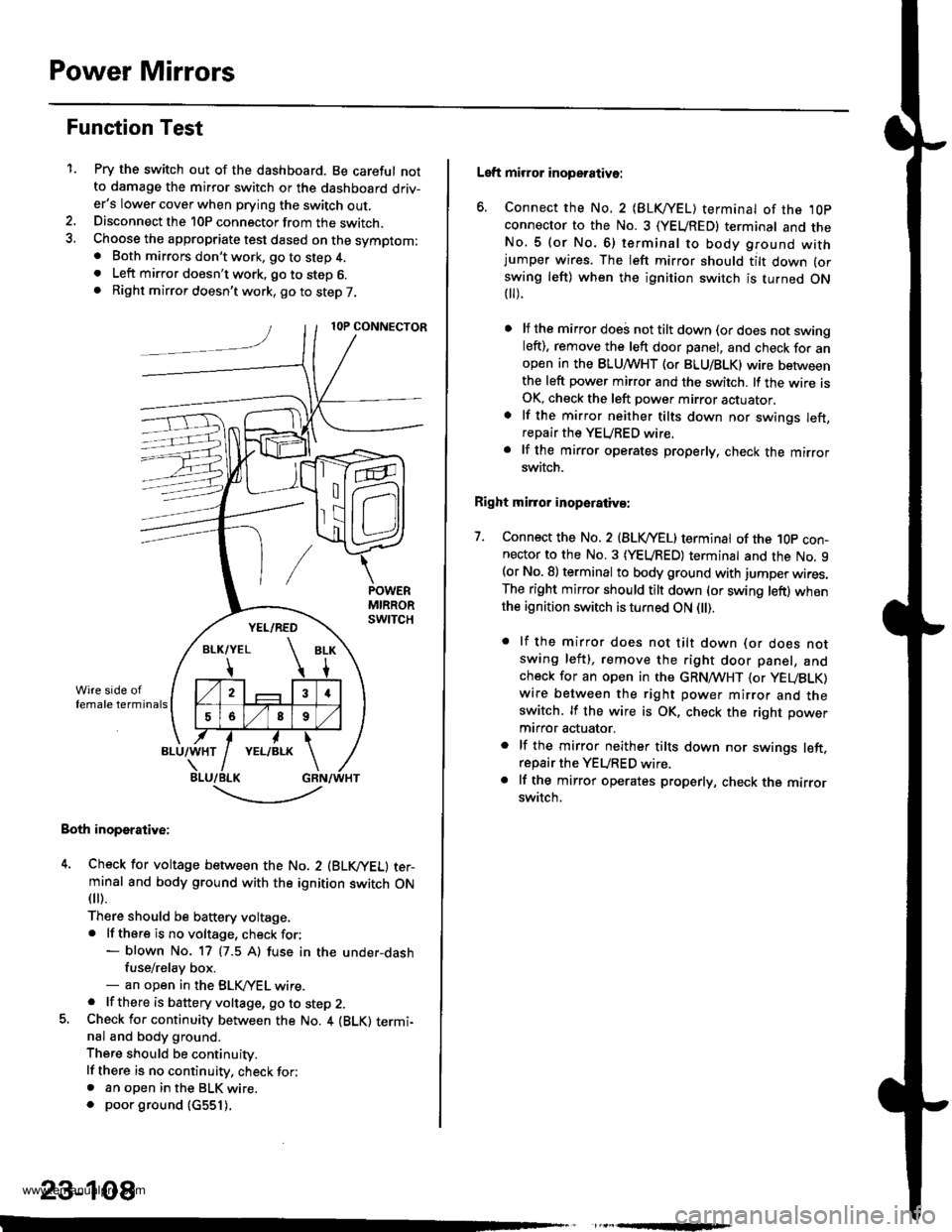
1.Pry the switch out of the dashboard. Be careful notto damage the mirror switch or the dashboard driv-er's lower cover when prying the switch out.Disconnect the 10P connector from the switch.Choose the appropriate test dased on the symptom:. Both mirrors don't work, go to step 4.. Left mirror doesn't work, go to step 6.. Right mirror doesn't work, go to step 7.
Both inoperative:
4. Check for voltage between the No. 2 (BLVYEL) ter-minal and body ground with the ignition switch ON
fl r).
There should be baftery voltage,. lf there is no voltage, check for:- blown No. 17 (7.5 A) fuse in the under-dashfuse/relay box.- an open in the BLK,/YEL wire.. lf there is battery voltage, go to step 2.5. Check for continuity between the No. 4 {BLK) termi-nal and body ground.
There should be continuity.
lf there is no continuity, check for;. an open in the BLK wire.. poor ground (c551).
,
-.t-..------'-
23-108
Left mirror inoperative:
6. Connect the No. 2 {BLKI/EL) terminal of the ,l0p
connector to the No. 3 (YEUREDI terminal and theNo.5 (or No.6) terminal to body ground withjumper wires. The left mirror should tilt down (or
swing left) when the ignition switch is turned ON t).
lf the mirror doei not tilt down (or does not swingleft), remove the left door panel, and check for anopen in the BLUMHT (or BLU/BLK) wire betweenthe left power mirror and the switch. lf the wire isOK, check the left power mirror actuator,
lf the mirror neither tilts down nor swings left,repair the YEURED wire.
lf the mirror operates properly, check the mirrorswitch.
Right mirror inoperaiiva:
7. Connect the No. 2 {BLVYEL) terminat of the 1Op con-nector to the No. 3 (YEURED) terminal and the No. 9(or No. 8) terminal to body ground with jumper wires.The right mirror should tilt down (or swing left) whenthe ignition switch is turned ON l).
. lf the mirror does not tilt down (or does notswing left), remove the right door panel, andcheck for an open in the GRN,4TVHT (or yEUBLK)
wire between the right power mirror and theswitch. lf the wire is OK, check the right power
mtrror actuator.
. lf the mirror neither tilts down nor swings left.repair the YEURED wire.. lf the mirror operates properly, check the mirrorswitch.
www.emanualpro.com
Page 1278 of 1395

Wipers/Washers
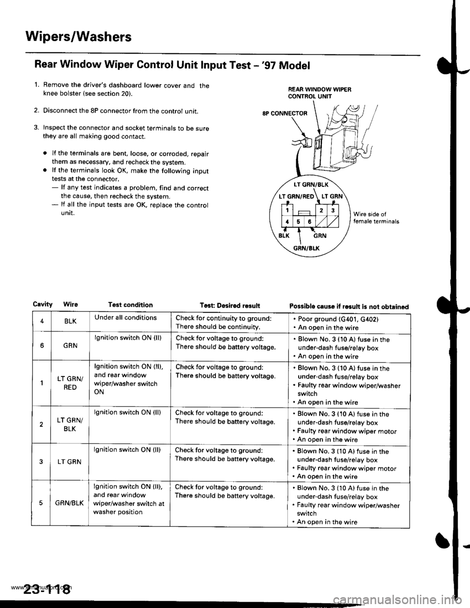
Rear Window Wiper Gontrol Unit lnput Test -'97 Model
Remove the driver's dashboard lower cover and theknee bolster {see section 20).
Disconnect the 8P connector from the control unit.
Inspect the connector and socket terminals to be surethey are all making good contact.
a lf the terminals are bent, loose, or corroded, repair
them as necessary. and recheck the system.. lf the terminals look OK, make the following input
tests at the connector.- lf any test indicates a problem, find and correct
the cause, then recheck the system.- lf all the input tests are OK, replace the control
UNII.
1.
LT GRN/BLK
T GRN/RED LT
12
16
GRN/BLK
8P CONNECTOF
CavityTest condhion Test Desir€d r93uhPossible cause il rasuh is not obtained
4BLKUnder all conditionsCheck for continuity to ground:
There should be continuity.
. Poor ground (G401, c402). An open in the wire
GRN
lgnition switch ON (lllCheck for voltage to ground;
There should be battery voltage.
Blown No. 3 (10 A) fuse in the
under-dash fuse/relay box
An open in the wire
'lLT GRN/
RED
lgnition switch ON ( ll),
and rear window
wiper/washer switch
ON
Check for voltage to ground:
There should be battery voltage.
Blown No. 3 (10 A) fuse in the
under-dash fuse/relay box
Faulty rear window wiper/washer
switch
An open in the wire
LT GRN/
BLK
lgnition switch ON (lllCheck for voltage to ground;
There should be battery voltage.
Blown No. 3 {10 A) fuse in the
under-dash fuse/relay box
Faulty rear window wiper motor
An open in the wire
LT GRN
lgnition switch ON (ll)Check for voltage to ground:
There should be battery voltage.
Blown No.3 {10 A)fuse in the
under-dash fuse/relay box
Faulty rgar window wiper motorAn open in the wire
5GRN/BLK
lgnition switch ON lll),
and rear window
wiper/washer switch at
washer position
Check for voltage to ground:
There should be battery voltage.
Blown No.3 (10 A) fuse in the
under-dash fuse/relay box
Faulty rear window wiper/washer
switch
An open in the wire
23-118
www.emanualpro.com
Page 1281 of 1395
Hatch Glass Opener
Circuit Diagram
BATTEFY
@*"
UNDER.H@D FUSE/RELAY BOX
|-*;rr^!...',r,*;l.......1<\o<
+l
I
I
IWHT/GRN
WHT/GRN
II
rt
KEYLESSiPOWEF DOOB LOCKCONTROL UNIT
V
IIIYEL
HATCHGLASSOPENERsoLENOr0
J
TBLK
I
out,G631
WHT/GBN
Ot-
23-121
1. Remove the dashboard lower cover (see section
20).
2. Disconnect the 2P connector from the switch.
3. Remove the switch from the dashboard lower
cover.
Switch Test
DASHBOANDLOWER COVER
HATCH GLASSOPENER SWITCH
Check for continuity between the No. 1 and No. 2
terminals.
. There should be continuity when the switch is
pushed.
. There should be no continuity when the switch is
released.
www.emanualpro.com
Page 1313 of 1395

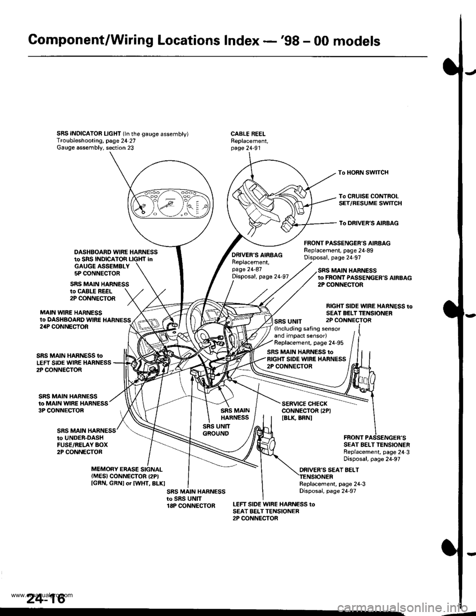
Gomponent/Wiring Locations Index -'98 - 00 models
SRS INDICAIOR LIcHT (ln the gauge assembty)Troubleshooting, page 24 27Gauge assembly. section 23
DASHBOARD WIRE HARNESSto SRS INDICATOR LIGHf inGAUGE ASSEMBLY5P CONNECTOR
FRONT PASSENGER'S AIRBAGReplacement, page 24-89Disposal, page 24 97
CABLE REELReplacement,page 24-91
To HORN SWITCH
To CRUISE CONTROLSET/RESUME SWTCH
To DRIVER'S AIRBAG
ro CABLE REEL2P CONNECTOR
MAIN VYIRE HARNESSto DASHBOARD WIRE HARNESS
SRS MAIN HARNESS
ORIVER'S AIRBAGReplacement,page 24-87Disposal, page 24-97
SRS UNIT
SRS MAIN HARNESSto FROI{T PASSENGER,S AIRBAG2P CONiIECTOR
RIGHT SIDE WIRE HARNESS toSEAI BELTTENSIONER2P CONNECTOR24P CONNECTOR
SRS MAIN
SRS MAIN HARNESS toLEFT SIDE WIRE HARNESS2P CONNECTOR
SRS MAIN HARNESSto MAIN WIRE HARNESS3P CONNECTOB
(lncluding safing sensorand impact sensor)Replacement, page 24-95
SRS MAIN HARNESS toRIGHT SIDE WIRE HARNESS2P CONNECTOR
SERVICE CHECKCONNECTOR I2PIIBLK BRNI
to UNDER-DASHFUSE/RELAY BOX2P CONNECTORSEAT BELT TENSIONERReplacement, page 24 3Disposal, page 24-97
ORIVER'S SEAT BELTMEMORY ERASE SIGNAL(MES) CONNECTOR I2PIIGRN, GRNI or IWHT, BLKIReplacement, page 24-3Disposal, page 24-97
LEFT SIDE WIRE HARNESS toSEAT BELTTENSIONER2P CONNECTOR
24-16
.4
www.emanualpro.com
Page 1330 of 1395
SRS Indicator Light Wire Connections
SRS Indicator Light Power Circuit
DASHBOARD WIRE HARNESS
YEL
BLK
To UNDER-DASHFUSE/RELAY BOX <_
20P CONNECTOR
To GAUGEcsog + assEMBLy
SRS Indicator Light Control Circuit
SRS MAIN HARNESS
)-MAIN WIRE HARNESS
VAIVBIt
To UNDER-DASHFUSE/BELAY BOX2P CONNECTOR
c414MAIN WIRE HARNESS 3P CONNECTORTerminal side of msle t€rminals
c415MAIN wlRE HARNESS 24P CONNECTORTerminal aide of male terminals
c502DASHBOARD WIRE HARNESS 2OP CONNECTORWire side of lemslo terminsls
c503OASHBOARD WIRE HARNESS 24P CONNECTORWire side of female t€rminal3
c509DASHBOABD WIRE HARNESS 5P CONNECTORWire sid€ ot lemale te.minals
c801SRS MAIN HARNESS 2P CONNECTORwire side ol f.male terminals
c803SRS MAIN HARNESS 3P CONNECTORWire side ol female terminals
c806SRS MAIN HARNESS T8P CONNECTORWire side of lomrle terminals
)
24-33
www.emanualpro.com
Page 1337 of 1395

Troubleshooting
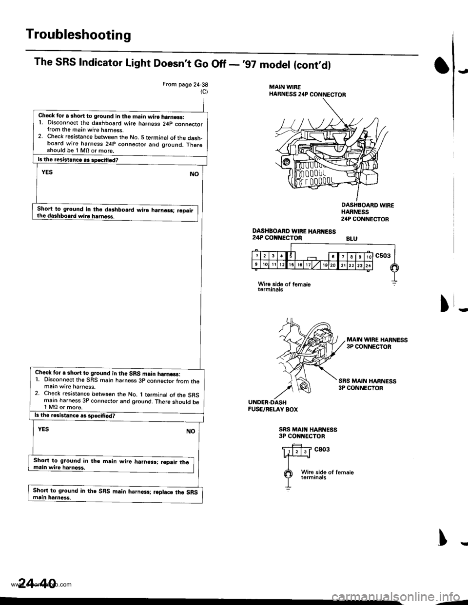
The SRS Indicator Light Doesnt Go Off -'97 model {cont'dl
From page 24-38
1C)
Check for a short to ground in tho main wire ha.n.3s:1. Disconnect the dashboard wire harngss 24p connectorfrom the main wire harness,2. Check resistance between the No. 5 terminal of the dash_board wire harness 24P connector and ground. Thereshould be 1 M0 or more.
Short to ground in tho deshbosrd wire harne.r; raD.irthe dashboard wiro harness.
Check tor a short to ground in tho SRS main hfina3!:1. Disconnect the SBS main harness 3p connector from themaan wire harness.2. Check resistance between the No. 1 terminal of the SRSmain harness 3P connector and ground. There should be1 MO or more.
Short to ground in tho main wire harnesr; ,opair th6main wire hamoss.
Short to ground in the SRS main hsrn6sa;.oplac. thc SRSmain harn6ss.
i,
MAIN WIREHARNESS 24P CONNECTOR
DASHBOARD WIRE HAff{ESS24P COi{NECTOR
OASHBOARD WIREHARNESS24P CONNECTOR
BLU
)
MAIN wlRE HARNESS3P CONNECTOB
SRS MAIN HARNESS3P CONNECTOR
UNDER.OASHFUSE/RELAY BOX
SRS MAII{ HARI{ESS3P CONNECTOR
cao3
)r
24-40
Wire side of femalet6rminals
-1
www.emanualpro.com
Page 1342 of 1395
Chock fo. a short to glound in tho main wire harn63:
1. Disconnect tho dashboard wire harnoss 24P connector
from the main wire harness.2. Check resistance between the No 5terminal oIthedash-
board wire harness 24P connector and ground. There
should bs 1 Mo or more.
Short to ground in tho dashboatd wilo harnots; repair
Chcck for a short to ground in the SRS main harnoss:
1. Disconnect the SRS main hart\ess 3P connector {rom the
main wire harness,2. Check resistance between the No. 1 terminal of the SRS
main harness 3P connector and ground. There should be
1 MO or more.
Short to ground in the mlin wire harnoss; .epair lh€
mlin wira harness.
Short to ground in thc SRS mtin hemess; replace tho SRS
J
From page 24-431C)
MAIN WIREHABNESS 2,lP CONNECTOR
OASHBOARD WIRE HARI{ESS
24P CONNECTOR
OASHBOARD WIREHARNESS2,rP CONNECTOR
BLU
)
MAIN WIRE3P CONNECTOR
cToR FUSE/RELAY BOX
SRS MAIN HARNESS3P CONIIECTOR
c803
)(cont'd)
24-45
www.emanualpro.com
Page:
< prev 1-8 9-16 17-24