Page 827 of 1395
Front Driveshafts
Reassembly (cont'd)
16. Unwind the boot band tool. and cut off the excess
free end of the band to leave a 5 - 10 mm (0.2 - 0.4
in) tail protruding from the clip.
5- 10 mm
10.2 - 0.4 in,
Bend the band end by tapping it down with a ham-
mer,
NOTE;
. Make sure the band does not move,
. Remove any grease remaining on the surround-
ing surfaces.
18, Install the new set ring.
17.
16-12
Outbosrd Joint Sids:
1. Wrap the splines with vinyl tape to prevent damage
to the boot.
OUTBOARD BOOT
2, Install the boot band and outboard boot, then
remove the vinyl tape. Take care not to damage the
boot.
3. Install the stop ring into the driveshaft groove.
VINYL TAPE
DRIVESHAFT
www.emanualpro.com
Page 828 of 1395
4. lnsert the driveshaft into the outboard ioint until the
stop ring is close on the joint.
DRIVESHAFT
To completely seat the outboard joint, pick up the
driveshaft and joint. and drop them from about 10
cm (4 to 5 inches) onto a hard surface, Do not use a
hammer as excessive force may damage the drive-
shaft.
i/,,,t| :l,r;;:,:.'i,,1;'/l
6. Check the alignment of the paint mark with the out-
board joint end.
DRIVESHAFT
1.Pack the outboard joint with the joint grease included
in the new joint boot set.
Grease quantity:
Outboard ioini: '97 model and '98 USA model
130 - 140 g {,1.6 - ,0.9 oz}'98 C8n8d8 modsl 8nd all '99 - 00 models
ll0 - tso g {i1.9 - 5.3 ozl
DRIVESHAFT
(cont'd)
16-13
www.emanualpro.com
Page 829 of 1395
Front Driveshafts
8. Fit the boot ends onto the driveshaft and outboard
lornt.
OUTBOARD BOOT fiPE)
OUTBOARD BOOT
OUTBOARD BOOT
Reassembly (cont'd)
Install the boot bands,
. For all '97 models and'98
step 13.
. For'98 Canada models andgo to step 10.
OUTBOARD JOINT
USA models, go to
all '99 - 00 models,
10. Set the ear clamp band by threading the tab into theholes of the band.
16-14
11. Close the ear portion of the band with a commercially
available boot band pincers KENT-MOORE J-35910 or
equivalent.
BOOT BAND PINCERSKENT.MOORE J-35910or equivalent
12.Check the clearance between the closed ear Dortionof the band, lf the clearance is not within the stan-dard, close the ear portion of the band further.
6.0 mm 10.24 in) MAX
3.0 mm {0.12 in} MAX
EAR PORTION
www.emanualpro.com
Page 830 of 1395
13. Fit the boot ends onto the driveshaft and the out-
board joint.
14. Fit the double looD boot bands onto the boot ends
15.
16.
Pull up the slack in the band by hand.
Mark a position on the band 10 - 14 mm (0.4 - 0.6
in.) from the clip.
Thread the free end of the band through the nose
section of a commercially available boot band tool
(KD-3191 or equivalentl, and into the slot on the
winding mandrel.
17.
BOOT BAND TOOL(Commercially available)KD-3191 or equivalentMark spot.
(cont'd)
16-15
CLIP
www.emanualpro.com
Page 831 of 1395
Front Driveshafts
Reassembly (cont'dl
18.
19.
Place a wrench on the winding mandrel of the boot
band tool, and tighten the band until the marked
spot on the band meets the edge of the clip.
Lift up the boot band tool to bend the free end of
the band 90" to the clip. Center-punch the clip, then
fold over the remaining tail onto the clip.
Unwind the boot band tool. and cut off the excess
free end of the band to leave a 5 - 10 mm (0.2 - 0.4
in) tail protruding from the clip.
20.
CLIP
16-16
21, Bend the band by tapping it down with a hammer.
NOTE: Make sure the band and the clip does not
interfere with anything, and the band does not
move, Remove any grease remaining on the sur-
rounding surfaces.
BAND END
www.emanualpro.com
Page 832 of 1395

Front Driveshafts
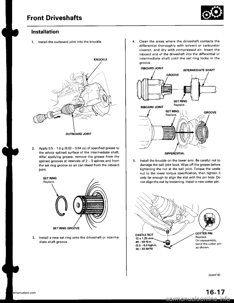
lnstallation
1. Install the outboard ioint into the knuckle.
KNUCKLE
OUTBOARD JOINT
Apply 0.5 - 1.0 g (0,02 - 0.04 oz) of specified grease to
the whole sDlined surface of the intermediate shaft.
After applying grease. remove the grease from the
splined grooves at intervals of 2 - 3 splines and from
the set ring groove so air can bleed from the inboard
ioint.
SET RINGReplace.
SET RING
Install a new set ring onto the driveshaft or interme-
diate shaft groove.
4. Clean the areas where the driveshaft contacts the
differential thoroughly with solvent or carburetor
cleaner, and dry with compressed air. Insert the
inboard end of the driveshaft into the differential or
intermediate shaft until the set ring locks in the
groove.
INBOARD JOINT
INBOARD JOINT
lnstall the knuckle on the lower arm. Be careful not to
damage the ball joint boot. Wipe off the grease before
tightening the nut at the ball joint. Torque the castle
nut to the lower torque specification. then tighten it
only far enough to align the slot with the pin hole. Do
not align the nut by loosening. lnstall a new cotter pin.
5.
CASTLE NUT12 x 1 .25 mm49-59Nm(5.0 - 6.0 kgl'm,36 - 4:l lbl.ft)
COTTER PINReplace.On reassembly,bend the cotter pin
(cont'd)
16-17
Replace.
www.emanualpro.com
Page 837 of 1395

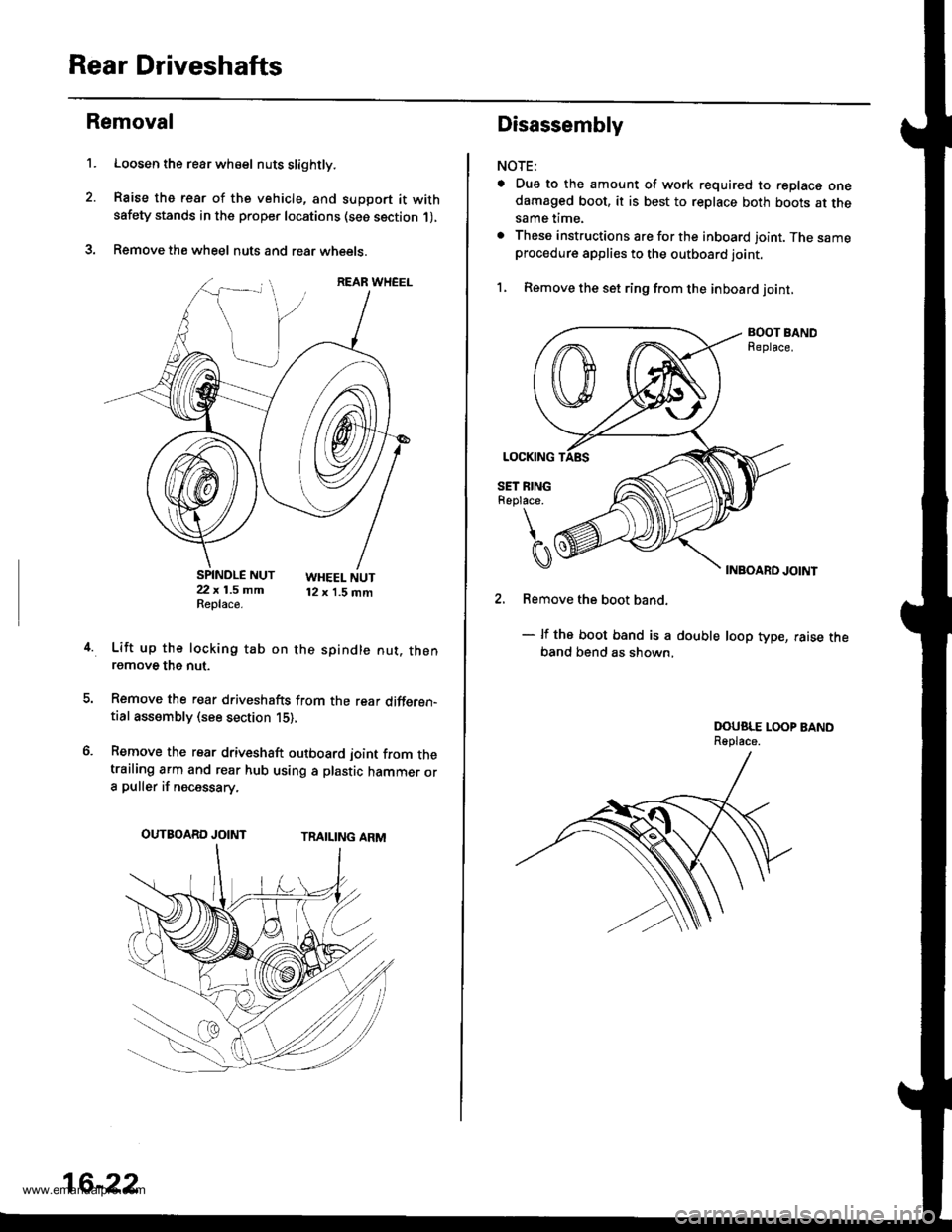
Rear Driveshafts
't.
Removal
Loosen the rear wh€el nuts slightly.
Raise the rear of the vehicle, and support it withsafety stands in the proper locations (see section 1),
Remove the wheel nuts and rear wheets.
SPINDLE NUT22 x 1.5 mmReplace.
WHEEL NUT12 x 1.5 mm
4.Lift up the locking tab on the spindle nut. thenremove the nut.
Remove the rear driveshafts from the rear differen-tial assembly (see section 15),
Remove the rear driveshaft outboard joint from thetrailing arm and rear hub using a plastic hammer ora puller if necessary.
TRAILING ARMOUTBOARD JOINT
16-22
Disassembly
NOTE:
a Due to the amount of work required to replace onedamaged boot, it is best to replace both boots at thesame time.
. These instructions are for the inboard joint. The sameprocedure applies to the outboard joint.
1, Remove the set ring from the inboard joint,
BOOT BANDReplace.
INBOARD JOINT
2. Remove the boot band.
- lf the boot band is a double loop type, raise theband bend as shown,
DOUSLE LOOP BANDReplace.
www.emanualpro.com
Page 838 of 1395
3. Mark each roller and inboard joint to identify the
locations of rollers and grooves in the inboard joint.
Then remove the inboard joint on the shop towel.
INBOARD JOINTCheck splines and driveshaft ringfor wear or damage,Check inside bore for wear.Inspect {or cracks,DRIVESHAFT RING
M.rks
SHOP TOWEL
Mark the rollers and spider to identify the locations
of the rollers on the sgider, then remove the rollers,
ROLLER
Remove the circlip.
Mark the spider and driveshaft to identify the posi-
tion of the spider on the shaft.
Remove the spider using a bearing remover.
0\
t
ICIRCLIP
Mark
7.
Marks
DRIVESHAFT
INEOARD BOOTInspect for cracking,splitting and wear.
10.
'1 1.
8. Wrap the splines on the driveshaft with vinyl tapeto
prevent damage to the boots.
DRIVE
Remove the boot band and boot from the drive-
shaft. Take care not to damage the boot.
Remove the vinyl tape.
Inspect the driveshaft for damage and other faults.
16-23
www.emanualpro.com