Page 144 of 1395

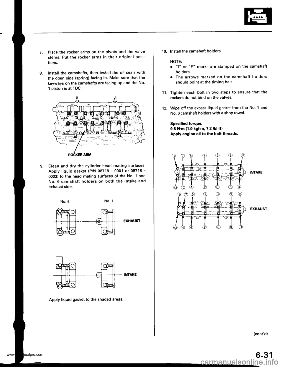
7.Place the rocker arms on the pivots and the valve
stems. Put the rocker arms in their original posi-
lrons.
lnstall the camshafts, then install the oil seals with
the open side (spring) facing in. Make sure that the
keyways on the camshafts are facing up and the No.
1 piston is at TDC.
Clean and dry the cylinder head mating surfaces.
Apply liquid gasket (P/N 08718 - 0001 or 08718 -
0OO3) to the head mating surfaces of the No. 1 and
No. 6 camshaft holders on both the intake and
exhaust side.
L
No. I
EXHAUST
II{TAKE
Apply liquid gasket to th€ shaded areas.
't't,
'10. lnstall the camshaft holders.
NOTE:
o "1" or "E' marks are stamped on the camshaft
holders.
. The arrows marked on the camshaft holders
should point at the timing belt.
Tighten each bolt in two steps to ensure that the
rockers do not bind on the valves.
Wipe off the excess liquid gasket from the No. 1 and
No. 6 camshaft holders with a shop towel,
Specified torque:
9.8 N.m (1.0 kgf.m, 7.2 lbf.ft)
Apply engine oil to the bolt ihreads.
I?,ITAKE
EXHAUST
(cont'd)
6-31
www.emanualpro.com
Page 145 of 1395

Cylinder Head
Installation (cont'dl
'13. Align the marks on the cylinder head plug to thecylinder head upper surface, then install the cylin
der head plug in the end of the cylinder head.
CYLINOER HEADPLUGReplace.
lnstallthe back cover.
To set the camshafts at TDC position for the No. lpiston, align the holes in the camshafts with theholes in the No. l camshaft holders and insert 5.0mm pin punches in the holes. Install the keys into
the camshaft grooves.
37 N m (3.8 *gl.m, 27 lbt.tr)
9.8 N.m (1.0 kgtm,7.2|hrftl
Push the camshaft pulleys onto the camshafts. thentighten the retaining bolts to the torque specified.
6-32
14.
KEYS
I x 1.25 mm
6x1.0mm
Install the timing belt (see page 6-1 1).
Adjust the valve clearance (see page 6-3).
Thoroughly clean the head cover gasket and thegroove.
lnstall the head cover gasket in the groove of thecylinder head cover. Seat the head cover gasket in
the recesses for the camshaft first, then work it into
the groove around the outside edges. Make sure thehead cover gasket is seated securely in the corners
of the recesses with no gap.
17.
'18.
19.
www.emanualpro.com
Page 161 of 1395
Piston Pins
lnstallation
The arrow must face thetiming belt side ot theengine and the connectingrod oil hole must face therear of the engine.
CONNECTING ROOotL Hor.E
1. Adjust the length B of the piston pin driver and shaft.
B: 49.70 mm (1.957 in)
PISTON PIN DRIVER SHAFT0t973 - P€qxtlo
Place the piston on the
pin in with a hydraulic
recessed portion of the
on the piston base head.
ffi*r,"ron'nl
PILOT COLLAROTLAF - PF3O1(x'
PISTON PIN BASE INSERT07GAF - PH6o3ttO
PISTON BASE HEADOTHAF - PL2O102
PISTON BASE07973 - 6670500
piston base and press the
press. Make sure that the
piston aligns with the lugs
7-15
www.emanualpro.com
Page 166 of 1395

PistonsCrankshaft
Installation
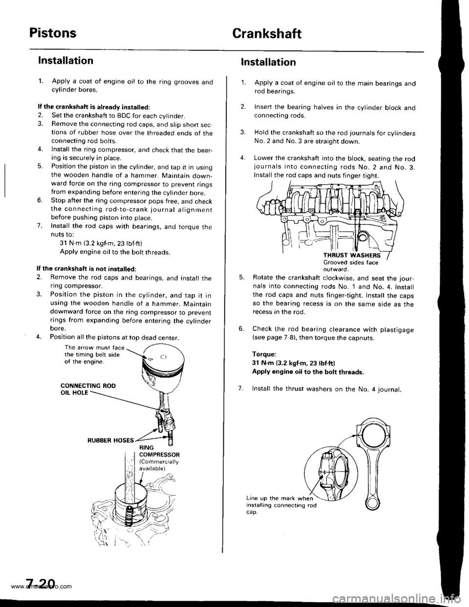
1. Apply a coat of engine oil to the ring grooves andcylinder bores.
It the crankshaft is already installed.
2. Set the crankshatt to BDC for each cylinder.3. Remove the connecting rod caps, and slip short sections of rubber hose over the threaded ends of theconnecting rod bolts.
4. lnstall the ring compressor, and check that the bear-ang is securely in place.
5. Position the piston in the cylinder, and tap it in usingthe wooden handle of a hammer. Maintain down-ward force on the ring compressor to prevent ringstrom expanding before entering the cylinder bore.6. Stop after the ring compressor pops free, and checkthe connecting rod-to-crank journal alignmentbefore pushing piston into place.
7. Install the rod caps with bearings, and torque theNUIS IO:
31 N.m (3.2 kgf.m,23 tbf.ft)
Apply engine oil to the bolt threads.
lf the crankshaft is not installed:
2. Remove the rod caps and bearings, and install theflng compressor.
3. Position the piston in the cylinder, and tap it inusing the wooden handle of a hammer. Maintaindownward force on the ring compressor to prevent
rings from expanding before entering the cylinderoore,
4. Position all the pistons at top dead center.
The arrow must facethe timing belt sideof the engine.
CONNECTING ROOOIL HOLE
RUBBER HOSES
7 -20
\-\
3.
4.
1.
6.
Installation
Apply a coat of engine oil to the main bearings androd bearings.
Insert the bearing halves in the cylinder block andconnect|ng rods.
Hold the crankshaft so the rod journals for cylindersNo.2 and No. 3 are straight down.
Lower the crankshaft into the block, seating the rodjournals into connecting rods No.2 and No.3.Install the rod caps and nuts finger tight.
outward.
Rotate the crankshaft clockwise, and seat the jour
nals into connecting rods No. 1 and No. 4, Install
the rod caps and nuts finger-tight. Install the capsso the bearing recess is on the same side as therecess an the rod.
Check the rod bearing clearance with plastigage(see page 7 8). then lorque the capnuts.
Torque:
3l N.m 13.2 kgf.m, 23 lbt.ftl
Apply engine oil to the bolt thleads.
5.
7. Install the thrust washers on the No. 4 journal.
Line up the mark wheninstalling connecting rodcap.
www.emanualpro.com
Page 169 of 1395
Oil Seals
18. Tighten the bolts and nuts finger tight at six points.
Tighten all bolts and nuts, starting from nut O. clock-
wise in three steps. Excessive tightening can cause
distortion ot the oil pan gasket and oil leakage.
Torque: 12 N.m (1.2 kgt.m,8.7 lbtft)
19.
1.
lnstallation
Dry the crankshaft oil seal housing.
Apply a light coat of grease to the crankshsft and to
the lips of the seals.
Using the special tool, drive in the timing pulley-end
seal until the driver bottoms against the oil pump.
When the seal is in place, clean any excess grease
off the crankshaft and check that the oil seal lip is
not distorted,
SEAL DRIVEROTLAD - PT3O1OAlnstall sealwith theparts number sidefacing out.
(cont'd)
7-23
www.emanualpro.com
Page 179 of 1395

1.
2.
3.
RemovaUlnspection/lnstallation
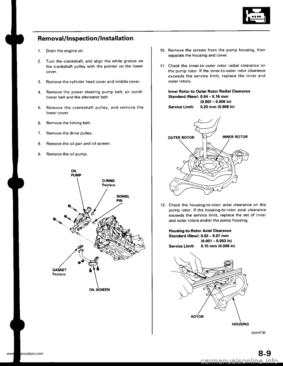
Drain the engine oil.
Turn the crankshaft, and align the white groove on
the crankshaft pulley with the pointer on the lower
cover.
Remove the cylinder head cover and middle cover.
Remove the power steering pump belt, air condi-
tioner belt and the alternator belt.
Remove the crankshaft pulley, and remove the
lower cover.
6. Remove the timing belt.
7. Remove the drive pulley.
8. Remove the oil pan and oil screen.
9. Remove the oil pump.
orLPUMP
OLRINGReplace.
5.
OIL SCREEN
10.
ll.
Remove the screws from the pump housing, then
separate the housing and cover.
Check the inner-to-outer rotor radial clearance on
the pump rotor. lf the inner-to-outer rotor clearance
exceeds the service limit. replace the inner and
outer rotors.
lnner Rotor-to Outar Rotor Radial Clearance
Standard {Newl: 0.04 - 0.16 mm
{0.002 - 0.006 inl
Service Limit: 0.20 mm (0.008 in)
Check the housing-to-rotor axial clearance on the
pump rotor. lf the housing-to-rotor axial clearance
exceeds the service limit. replace the set of inner
and outer rotors and/or the pump housing.
Housing-to-Rotor Axial Clearance
Standard {New): 0.02 - 0.07 mm
{0.001 - 0.003 in)
So|'�ice Limit: 0.15 mm (0.006 inl
(cont'd)
8-9
HOUSING
www.emanualpro.com
Page 199 of 1395
Inspection
1.
2.
Remove the timing belt (see section 6)
Turn the water pump pulley counterclockwise.
Check that it turns freely.
Check for signs of seal leakage.
NOTE: A small amount ol "weeping" from the bleed
hole is normal.
BIIED HOLE
Replacement
1. Remove the timing belt (see section 6).
2. Remove the water pump by removing five bolts
3, Inspect, repair and clean the O-ring groove and the
mating surface with the cylinder block.
Replace.6x1.0mm't2 N.m 11 2 kgf m.
8.7 tbf.ftl
4. lnstall the water pump in the reverse order of removal.
-
@-
I
I
10-1 1
www.emanualpro.com
Page 266 of 1395

Troubleshooting
Troubleshooting Procedures (cont'dl
Symptom Chart
Listed below are symptoms and probable causes for problems that DO NOT cause the Malfunction Indicator Lamp (MlL) tocome on. lf the MIL was reported on, go to page 11-60.Troubleshoot each probable cause in the order listed (from left to right) until the symptom is eliminated,The probable cause and troubleshooting page reference can be found below.
Other Probable Causes for an engine that will not start:- Compression- Intake air leakage- Engine locked up- Timing belt- Starting system- Overheating- Battery
SYMPTOMPROBABLE CAUSE
Engine will not sta rt4, 2,3,5,20, 't5, 1
Hard starting2, 4, 12,17, 14, 't9
Cold fast idle too low7, a,9, 6, 17
Cold fast idle too high7,8,9,11,10
ldle speed fluctuates9,7,8, 't1, 10
Misfire or rough runningTroubleshoot for misfire on pages '11-126, 1|21LOl/\/ power2, 10,11, 13, '17, 18,20
Engine stalls2, 4, 12,1,20,9,5, 't6
Probable Cause List (For the DTC Ch8rt, see page ll-75.)
Probable CausePageSystem
Engine controt ruoaute (ecvtffi'I11-42
I 1-178Fuel oressure
PGM-Fl main relav
lgnition system
Crankshatt Position/Top Dead Center/Cylinder position sensor circuit
Intake Air Temperature (lAT) sensor ctrculr
ldle Air Control (lAC) Vatve
Fast idle thermo valve
ldle speed adjustment
Throttle body
Throftle cable
Manifold Absolute P."""rr"ffi
Throftle Position (TP) sensor
Barometric pressur" (gnno-
Ay'T gear position signal
Brake switch signal
Air Cleaner
Three Way Catalytic Converter (TWC)
Evaporative emission (EVAP) control
Contaminated fuel
1 1- 187
Section 4
5't1-'t31,146
6I '�t-95
711-152
81'l-168
1 1- 169
1011-196'1111-'194
12'1 'l -90
1 1- 103
1411-137
15Section 14
161 1- 166
17r 1-194
181 1,199'1911-203
20
11-64
www.emanualpro.com