Page 686 of 1395
Transmission
Removal (cont'd)
8. Disconnect the mainshaft sp€ed sensor, the shift
control solenoid valve, and the linear solenoid con-
necrors,
Remove the drain plug. and drain the automatic
transmission fluid {ATF). Reinstall the drain plug
with a new sealing washer.
DRAIN18 x 1.5 mm4e N.m rs.o ksr.m. 36 rbrft) ;:i:$: *o"*."
SENSOR CONNECTOR
14-170
OAMPER FORKReplace.
10. Remove the guard bar and the splash shield.
Remove the cotter pins and castle nuts, then sepa-
rate the ball joints from the lower arms (see section
18).
Remove the right damper fork bolt, then separateright damper fork and damper.
11.
12.
SELF.LOCKINGNUTReplace.
CASII.E NUT
DAMPER FORKBOLT
DAMPER PINCH BOLT
www.emanualpro.com
Page 777 of 1395

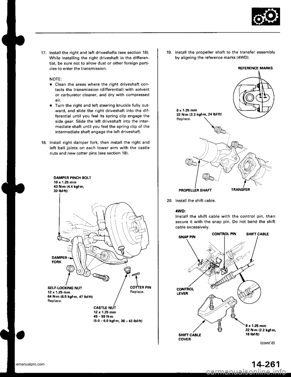
17. Install the right and left driveshafts (see section 18).
While installing the right driveshaft in the differen-
tial, be sure not to allow dust or other foreign parti-
cles to enter the transmission.
NOTE:
. Clean the areas where the right driveshaft con-
tacts the transmission (differential) with solvent
or carburetor cleaner, and dry with compressed
air.
. Turn the right and left steering knuckle fully out-
ward, and slide the right driveshaft into the dif-
ferential until you feel its spring clip engage the
side gear. Slide the left driveshaft into the inter-
mediate shaft until you feel the spring clip of the
intermediate shaft engage the left driveshaft,
18. Install right damper fork, then install the right and
left ball joints on each lower arm with the castle
nuts and new cotter pins (see section 18).
DAMPER PINCH BOLT10 x 1 .25 mm43 N.m 14.{ kgf.m,32 rbr.ftl
DAMPERFORX
SELF.LOCKING NUT12 x 1,25 mm6/t N m (6.5 kg{.m, a7 lbtft)Replace.
Replace.
CASTLE12 x 1.25 mm49 - 59 N.m15.0 - 6.0 kgl m, 36 - {3 lbtftl
19, Install the propeller shaft to the transfer assembly
by aligning the reference marks (4WD).
20.
8 x 1.25 mm32 N.m (3.3 kgt'm,2ir blft)
Feplace.
\
@_
PROPELLER SHAFT
lnstall the shift cable.
4WD:
Install the shift cable with the control pin, then
secure it with the snap Din. Do not bend the shift
cable excessivelv.
CONTROLLEVER
SHIFT CAALECOVER
8 x 1.25 mm22 N.m 12.2l'gl m,16 rbt.ftl
(cont'd)
REFERENCE MARKS
14-261
www.emanualpro.com
Page 778 of 1395
Transmission
Installation (cont'dl
2WD:
Install the control lever with a new lock washer to thecontrol shaft. Do not bend the shift cable excessivelv.
8 r 1.25 mm22 N.m|'2.2 kgt.m,16 rbf.ft)
SI{IFT CAELECOVER
LOCK WASHER 6 x 1.0 mmReplace. 14 N.m 11.4 kgt.m,10 tbr.frl
lnstallthe shift cable cover.
Install exhaust pipe A.
Connect the primary heated orygen sensor (primary
HO2S) connector.
GASKETSReplace.
22.
23.
10 x 1.25 m.n5r N.m {5.5 kgf.m,40 tbtftlReplace.
SELF.LOCKING
SELF-LOCKING NUT8 ! 1.25 mm16 N.m {1.6 kgf.m,12 lbf.fttReplace.
8 x 1.25 mm22 N.m {2,2 kgt.m, l5 lbt.ftl
SHIFT CABLE
14-262
24. Installthe splash shield and guard bar,
8 x 1.2524 N.m {2.a kgl.m,17 tbt.ftl
SPLASH SHIELD
GUARO BAR
25.
6r1.0|r|m9.8 N.m l1.0lgf.m, 7.2 tbtftl
Connect the mainshaft speed sensor, the shift con-trol solenoid valve, and the linear solenoid connec_tors,
SHIFT CONTROL SOLENOIDVALVE CONNECTOR
www.emanualpro.com
Page 818 of 1395

DriveshaftsFront Driveshafts
Inspection
Boot Damago
Check the boots on the driveshaft for cracks, damago,
leaking grease, and loose boot bands. lf any damags is
found, replace the boot and boot bands.
Looso Splines
Turn the driveshaft by hand, and make sure th€ splin€s
and joint are not excessively loose. lf damage is found,
replace the inboard joint.
Twisting or Crscking
Make sure the driveshaft is not twisted or crackod.
Replace it if necessary.
DRIVESHAFT
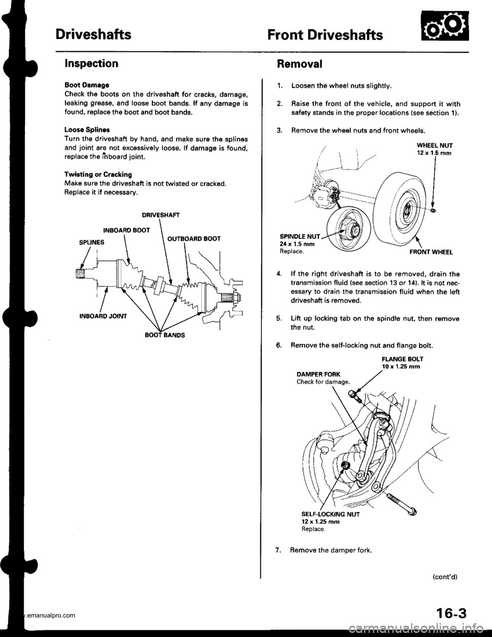
1.
Removal
Loosen the wheel nuts slightly.
Raise the front of the vehicle, and suppon it with
safety stands in the proper locations (see section 1).
Remove the wheel nuts and front wheels.?
SPINDLE NUT24 x 1.5 mmReplace.
lf the right driveshaft is to be removed, drain the
transmission fluid {see s€ction 13 or 14). lt is not nec-
essary to drain the transmission fluid when the left
driveshaft is removed.
Lift up locking tab on the spindle nut, then remove
the nut,
Remove the self-locking nut and flange bolt,
FLANGE BOLT10 x 1.25 mm
FRONT WHEEL
(cont'd)
6.
SELF"LOCKING NUT12 x 1.25 mmReplace.
7. Remove the damper fork,
16-3
www.emanualpro.com
Page 820 of 1395
13, Pull the knuckle outward, and remove the driveshaft
inboard joint from the differential case or bearing
suoDort.
KNUCKLE
Remove the driveshaft outboard joint from the front
wheel hub using a plastic hammer.
PLASTIC HAMMER
14.
DRIVESHAFT
DRIVESHAFT
Disassembly
Inboard Joint Sid€:
1, Carefully clamp the driveshaft in a vise with softjaws, then remove the set ring from the inboardjoint.
2. Remove the boot bands. Take care not to damage
the boot,
. lf the boot band is a locking tab type, pry up the
locking tabs with a screwdriver, and lift up the
end of the band.
. lf the boot band isawelded typeora low profile
type, carefully cut the boot band with a pair of
diagonal cutters.
. lf the boot band is a double loop type. lift up the
band bend.
Locking Tab
SET BINGReplace.
Welded
{cont'd)
16-5
www.emanualpro.com
Page 822 of 1395
Outboard Joint Side:
1. Lift up the three tabs with a screwdriver, then
remove the boot bands, Take care not to damage
the boot.
NOTE:
. lf the boot band is a double loop type, lift up the
band bend.
. lf the boot band is a welded type, cut the boot
band.
. lf the bootband isa lockingtabstype. pry upthe
tabs with a screwdriver, and lift up the end of the
oano.
Ear Clamp
EAR CLAMP BANDReplace.
2. Slide the outboard boot to the inboard ioint side.
Wipe off the grease to expose the driveshaft andthe outboard joint inner race.
Mark the driveshaft at the same position of the out-
board joint end with paint.
TAB
DRIVESHAFT
PAINT MARK
5, Carefullv clamD the driveshaft in a vise.
THREADED AOAPTER,2iI x 1.5 mm07xAc - 0010200
Remove the outboard joint using a special tool asshown.
Remove the driveshatt trom the vise
Remove the stop ring from the driveshaft.
o.
7.
8.
STOP RINGReplace.
Slide hammc..5/8'x lS Throad(Commerically, available)
DRIVESHAFT
www.emanualpro.com
Page 833 of 1395

Front DriveshaftsIntermediate Shaft
Installation {cont'd}
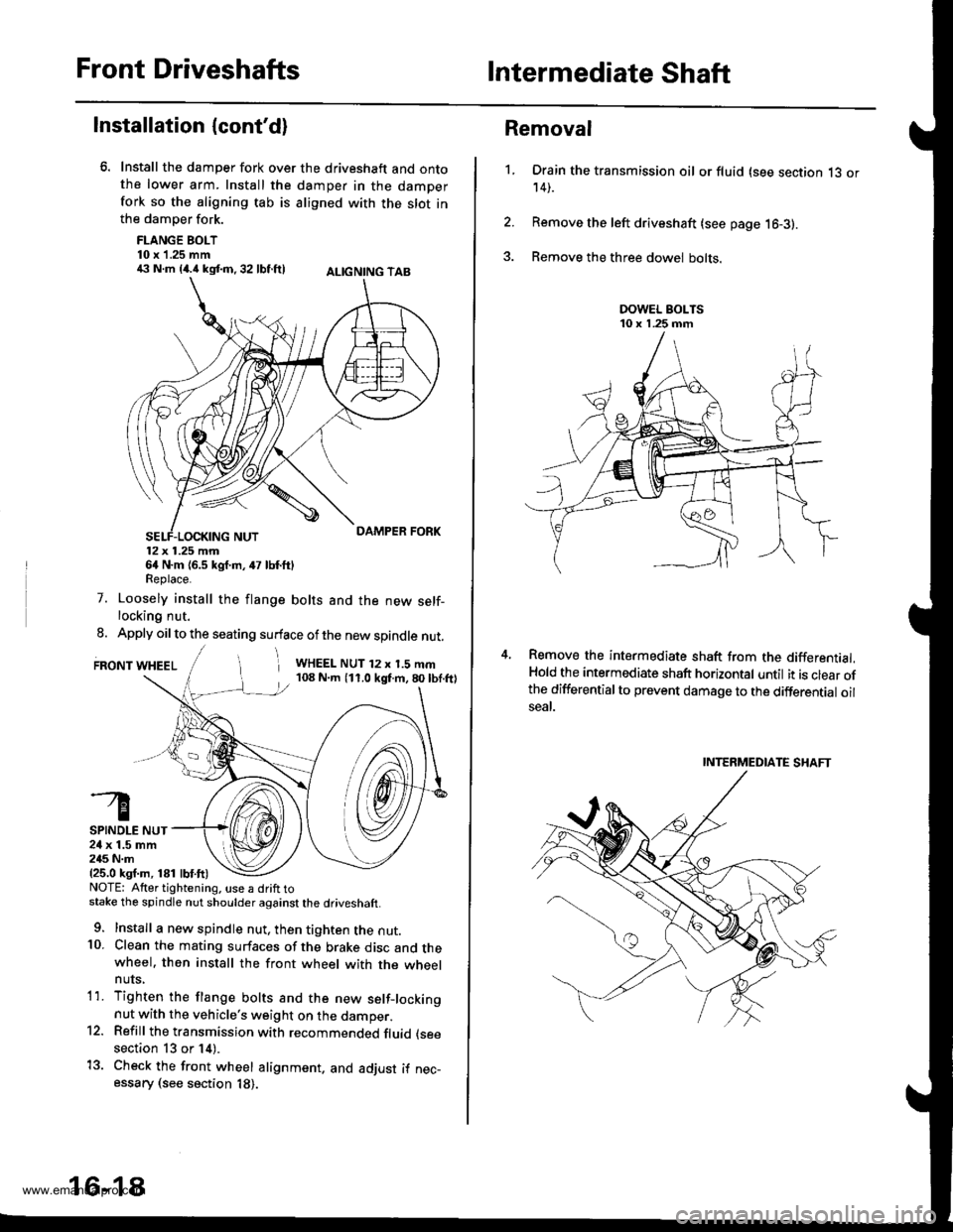
Install the damper fork over the driveshaft and ontothe lower arm. Install the damper in the damperfork so the aligning tab is aligned with the slot inthe damper fork.
FLANGE BOLT10 x 1.25 mm€ N.m {4.i1kst.n,32 lbf.ftl ALtcNtNG TAB
12x 1.25 mm64 N.m {6.5 kgf.m, 47 lbf.ftlReplace.
7. Loosely install the flange bolts and the new self-locking nut.
8. Apply oil to the seating surface of the new spindle nut.
FRONT WHEELi WHEEL NUT 12 x 1.5 mm108 N.m (11.0 kgf.m,80lbf.ftl
SPINDLE NUT24 x 1.5 mm245 N.m{25.0 ksf.m, 181 lbf.ft)NOTE: Atter tightening. use a drift tostake the spindle nut shoulder against the driveshaft.
9. Install a new spindle nut, then tighten the nut.10. Clean the mating surfaces of the brake disc and thewheel. then install the front wheel with the wheelnuts,
1'1. Tighten the flange bolts and the new setf-lockingnut with the vehicle's weight on the damper.12. Refill the transmission with recommended fluid (see
section 13 or 14).
13. Check the front wheel alignment. and adjust if nec-essary (see section 18).
16-18
1.
Removal
Drain the transmission oil or fluid (see section 13 or14).
Remove the left driveshaft (see page 16-3).
Remove the three dowel bolts.
Remove the intermediate shaft from the differential.Hold the intermediate shaft horizontal until it is clear ofthe differentialto prevent damage to the differential oilseal.
INTERMEDIATE SHAFT
www.emanualpro.com
Page 837 of 1395

Rear Driveshafts
't.
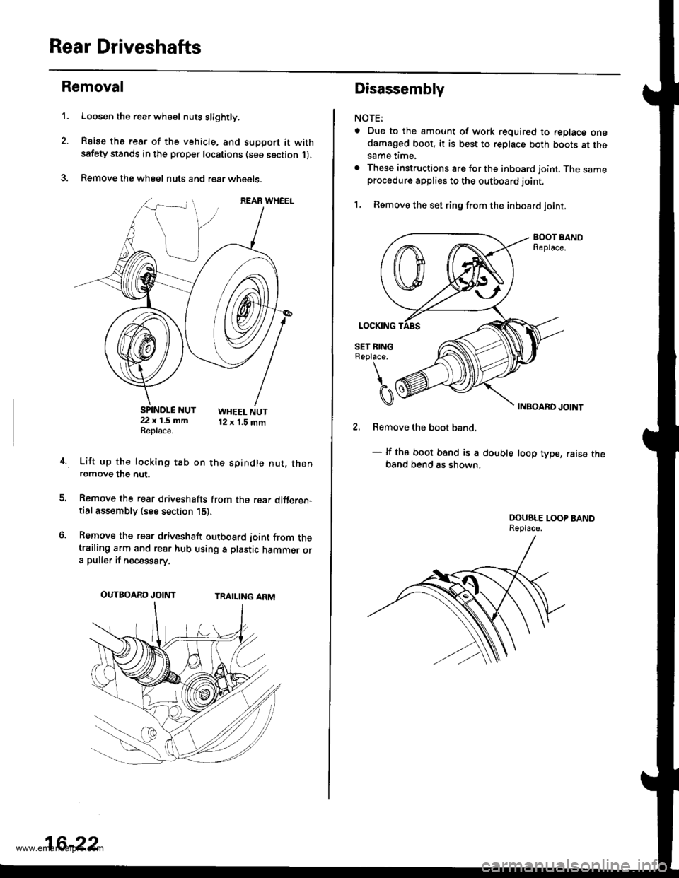
Removal
Loosen the rear wh€el nuts slightly.
Raise the rear of the vehicle, and support it withsafety stands in the proper locations (see section 1),
Remove the wheel nuts and rear wheets.
SPINDLE NUT22 x 1.5 mmReplace.
WHEEL NUT12 x 1.5 mm
4.Lift up the locking tab on the spindle nut. thenremove the nut.
Remove the rear driveshafts from the rear differen-tial assembly (see section 15),
Remove the rear driveshaft outboard joint from thetrailing arm and rear hub using a plastic hammer ora puller if necessary.
TRAILING ARMOUTBOARD JOINT
16-22
Disassembly
NOTE:
a Due to the amount of work required to replace onedamaged boot, it is best to replace both boots at thesame time.
. These instructions are for the inboard joint. The sameprocedure applies to the outboard joint.
1, Remove the set ring from the inboard joint,
BOOT BANDReplace.
INBOARD JOINT
2. Remove the boot band.
- lf the boot band is a double loop type, raise theband bend as shown,
DOUSLE LOOP BANDReplace.
www.emanualpro.com