Page 177 of 1395

Oil Pressure SwitchOil Pressure
Testing
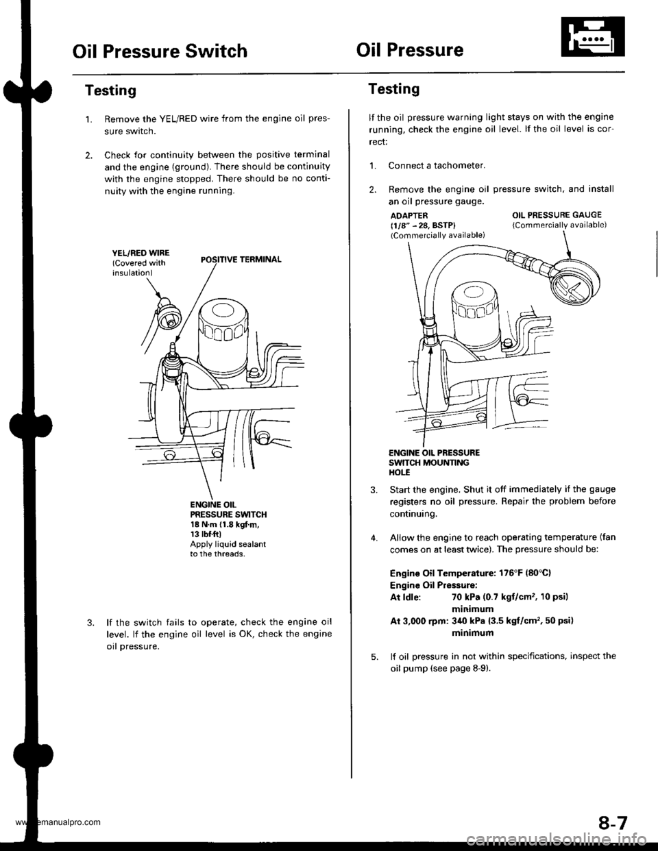
Remove the YEL/RED wire from the engine oil pres-
sure swrtcn.
Check for continuity between the positive terminal
and the engine {ground). There should be continuity
with the engine stopped. There should be no conti-
nuity with the engine running.
L
PRESSURE SWTCH18 N.m {1.8 kgf.m,13 tbr.ftlApply liquid sealantto the threads,
lf the switch fails
level. lf the engine
orl pressure.
to operate, check the engine oil
oil level is OK, check the engine
Testing
lf the oil pressure warning light stays on with the engine
running, check the engine oil level. lf the oil level is cor-
rect:
L Connect a tachometer.
2. Remove the engine oil
an oil pressure gauge.
ADAPTER(1/8" - 28, BSTP)(Commercially available)
pressure switch. and install
OIL PRESSURE GAUGE
{Commercially available)
4.
ENGINE OIL PRESSURESWTTCH MOUNNNGHOt-E
Start the engine. Shut it off immedjately if the gauge
registers no oil pressure. Repair the problem before
continuing.
Allow the engine to reach operating temperature (fan
comes on at least twice). The pressure should be:
Engino Oil Temperature: 176'F (80'C)
Engine Oil Pressure:
At ldle:70 kPa (0.7 kgt/cm'�, 10 psil
minimum
Ai 3,000 rpm: 3/r0 kPa {3.5 kgt/cm', 50 psi)
minimum
lf oil pressure in not within specifications, inspect the
oil pump (see page 8-9).
8-7
www.emanualpro.com
Page 189 of 1395
Cooling
f ffustrated Index ........... ..... 1O-2
Radiator
Rep|acement ...........,....,...................... 10-4
Engine Coolant Refilling and
Bleeding ..,.,................. 10-5
Cap Testing .................... 10-7
Testing ......10-7
Thermostat
Rep|acement ....................................... 10-8
Testing ...... 10-9
Water Pump
lllustrated lndex ....,..... .. 10-10
Inspection . 10-1 1
Replacement ....................................,.. 10-1 1
Fan Gontrol
Component Location Index ............... 10-12
Circuit Diagram ............. 10-13
Fan Motor Testing ......... 10-14
Radiator Fan Switch Testing ............. 10-14
Coolant Temperature Gauge
Gauge Testing ............... 10-15
Coolant temperature Sending
Unit Testing ........,....... 10-15
www.emanualpro.com
Page 198 of 1395
Water Pump
lllustrated Index
ENGINE COOLANTTEMPERATURE IECTISENSOR18 N.m 11,8 kgt.m,13 tbt.ftl
COOLANTTEMPERATUREGAUGEUNIT
6x1.0mm9.8 N'm (1.0 kgf.m,7.2 tbt frl
9 N.m {0.3 kgf.m,7 tbf.fttApply liquid gasketto the threads.
WATER OUTLETCOVERApply liquid gasker part No.087'18 - 0001 or 08718 - 0003to the mating surface.
RADIATOR FAN SWITCH2il N.m (2.i1 kgl.m,17 tbfft)
WATER PUMPlnspection, page 10-11
O-RINGReplac€.
6xl,0mm12 N.tn n.2 lgl.rn,8.7 tbf'ft)
CONNECTINGPIPE
6x1.0mm12 N.m 11.2 kgf.m,8.7 tbtftl
10-10
www.emanualpro.com
Page 203 of 1395

Goolant Temperature Gauge
Gauge Testing
1. Check the No. 25 (7.5 A) fuse in the under-dash
fuse/relay box before testin9.
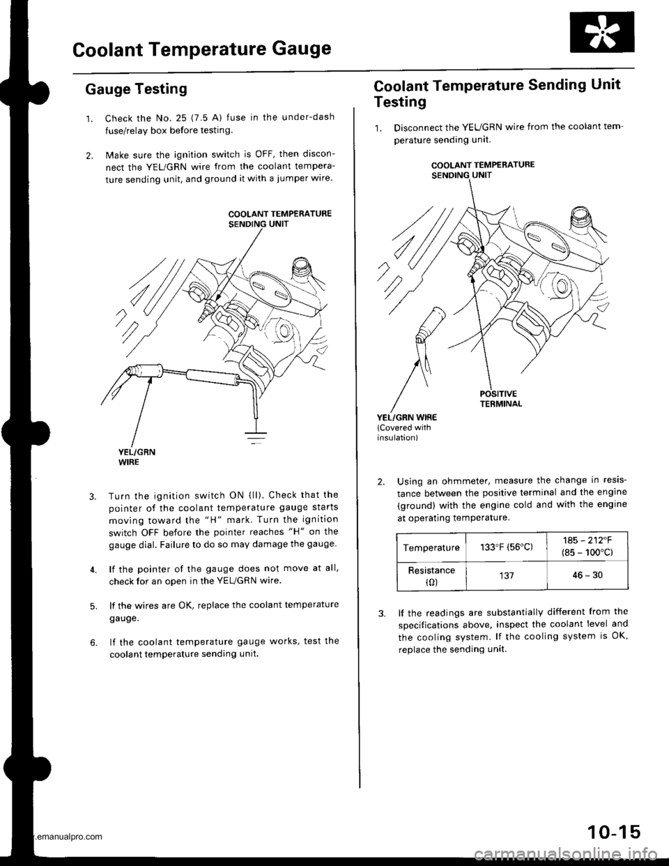
2. Make sure the ignition switch is OFF, then discon-
nect the YEL/GRN wire from the coolant tempera-
ture sending unit. and ground it with a jumper wire.
YEL/GRNWIRE
Turn the ignition switch ON {ll). Check that the
pointer of the coolant temperature gauge starts
moving toward the "H" mark. Turn the ignition
switch OFF before the pointer reaches "H" on the
gauge dial. Failure to do so may damage the gauge.
lf the pointer of the gauge does not move at all,
check for an open in the YEL/GRN wire.
lf the wires are OK, replace the coolant temperature
gauge.
lf the coolant temperature gauge works, test the
coolant temperature sending unit.
5.
COOLANT TEMPERATURE
Coolant Temperature Sending Unit
Testing
1. Disconnect the YEUGRN wire from the coolant tem
perature sending unit.
COOLANT TEMPERATURE
POSITIVETERMINAL
YEL/GRN WIRE(Covered withinsulation)
2. Using an ohmmeter, measure the change in resis-
tance between the positive terminal and the engine
(ground) with the engine cold and with the engine
at operating temPerature.
Temperature133.F (56'C)1A5 - 212F
(8s - 100'c)
Resistance(0)13746-30
3. lf the readings are substantially different from the
specitications above, inspect the coolant level and
the cooling system. lf the cooling system is OK,
replace the sending unit.
10-15
www.emanualpro.com
Page 204 of 1395

Fuel and Emissions
Special Tools ...................... 11-2
Component Locations
lndex ...................... ....,.... 11-3
Svstem Description
Vacuum Connections ...........,....,.,................. 1 1-9
Electrical Connections ................................... 1 1-15
System Connectors .,.,,.,............................,.,. 1 1-36
Troubleshooting
Troubleshooting Procedures,.,..................... 11-60
Engine Control Module/Powertrain ConttolModule Terminal Arrangement .............., 11-67
Diagnostic Trouble Code Chart .................... 1 t-75
How to Read Flowcharts .......,.....,.,............... I 1-79
PGM-Fl System
System Description .................,.,.,,,............... 1 1-80
Troubleshooting Flowcharts
Engine Control Module/PowertrainControl Module ........11-52
Manifold Absolute Pressure Sensor ............. 11-90
Intake Air Temperature Sensor .................... 1 1-95
Engine Coolant Temperature Sensor .,..,.,.... 1 1-99
Throttle Position Sensor ...........,.....,.,.,..,...... I 1'103
Primary Heated Orygen Sensor (Sensor 1) ... 11-110
Secondary Heated Oxygen Sensor{Sensor 2l .................. 1 1-117
Heated Oxygen Sensor Heater ..................... 11-121
Fuef Supply System ......11-124
Random Misfire ,....,.,..... 11-126
Mistire Detected in One Cylinder .....-........... 11-128
Knock Sensor ................ 11-130
CKP/TDC/CYP Sensor .................................... 1 1-131
Vehicle Speed Sensor ...............................,.... 1 1-135
Barometric Pressure Sensor .....,...,...,.,,........ 1 1-137
Electrical Load Detector ...,.,.......................... 1 1-138
CKF Sensor ................,.,, '11-112
ECM/PCM lnternaf Circuit ............................. 11'117
HO2S Replacement .,.,.,. 11-148
ldle Control System
System Description ............ 11-149
Troubleshooting Flowcharts
ldle Control System ...... 11-150
fdle Air Control Valve ......................,............. 11-152
Air Conditioning Signal ................................. I 1-155
Alternator FR Signal ...................................... 1 1-159
Starter Switch Si9na1 .................................... t l-161
Power Steering Pressure Switch Signal ...... 11-162
Brake Switch Si9na1 ...................................... 11-166
Fast ldle Thermo Valve .,.,.............................,.,.,. 11-168
ldle speed setting .............. 11-169
Fuel Supply System
Fuel Lines ............................ 11-171
Fuef Tube/Ouick-Conneci Fittings ..................... 11 -175
System Description ............ 11-178
Fuel Pressurg ...................... 11-178
Fuel Iniectors ................,..... 11-179
Fuel Pressure Re9u1ator .............................,.,...., f 1-181
Fuef Fifter ....,.,.,.,,,,.,............11-142
Fuel Pump ........................... 11-183
Fuel Gauge .......................... 11-184
Fuel Gauge Sending Unit ................................... I 1-185
Low Fuel Indicator System ...........,.,..,............... 1 1-185
PGM-FI Main Relay ............. 11-187
Fue|Tank................ ............. 11-191
Intake Air System
System Description ............ 11-193
Air Cleanel ,.,.,..................... 11-194
Throttle Cable ..................... 11-194
Throttle Body........ .............. 11-196
Emission Control System
System D$cription ...,....,.,. 11-199
Tailpipe Emission ............... 11-199
Three Way Catalytic Converter ..................,.,...,, 11-199
Positive Crankcase Ventilation System .,.,,,,.,.., 11-2O1
Evaporative Emission Controls .........,.,.,............ 11-203
www.emanualpro.com
Page 205 of 1395
Special Tools
Ref. No. Tool NumberDescriptionOty Page Reference
q
t3'
,3)l
6rl
A973X_041 _XXXXX
07JAZ 0010008
07PAZ , 0010100
07sAz - 001000A
07405 - 0040001
Vacuum Pump/Gauge,0 - 30 in.Hg
Vacuum/Pressure Gauge, 0 4 in.Hg
SCS Service Connector
Backprobe Set
Fuel Pressure Gauge
1
1
2
1
'11-201 . 208,214,
215,2't6,217 ,220,
221 , 222, 223, 224
11 207 , 224
11-60, 83, 88, 1 16,
128,200,205
11-62
11-178, 181
Special Tools
I
11-2
www.emanualpro.com
Page 210 of 1395

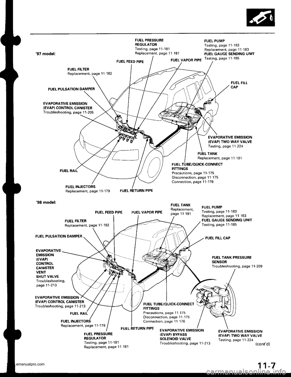
FUEL PRESSUREREGULATORTesting, page 11-181Replacement, page 11 181
FUEL PUMPTesting, page 11 183Replacement, page 11 183FUEL GAUGE SENDING UNITTesting, page 11 185
'97 model:
'98 model:
FUEL PULSATION DAMPER
EVAPORATIVE EMISSIONIEVAP) CONTROL CANISTERTroubleshooting. page 1'l-205
FUEL FILTERReplacement, page 11 182
FUEL INJECTORSReplacement, page 1 1-179
FUEL FEED PIPEFUEL VAPOR PIPE
FUELFITTINGS
FUEL FILLCAP
EVAPORATIVE EMISSION
IEVAPI TWO WAY VALVETesting, page 11 224
TANKReplacement, page 11 191
-CONNECT
Precautions, page 1 1-175Disconnection, page 11 175Connection, page 1 1-176
FUEL FILTERReplacement, page 11 182
FUEL FEED PIPEFUEL VAPOR PIPE
FUEI- TANKReplacement,page 1l 191
FUEL TUBE/OUICK.CONNECTFITTINGSPrecautions, page 11 '175
Disconnection, page 11 175Connection, page 11 176
FUEL PUMPTesting, page 11 183Replacement, page 11 183FUEL GAUGE SENDING UNITTesting, page 1l'185
FUEL FILL CAP
FUEL TANK PRESSURESENSORTroubleshooting, page 1 l-209
FUEL PULSATION DAMPER
EVAPORATIVEEMTSSTONIEVAPICONTROLCANISTERVENTSHUT VALVETroubleshooting,page 11'213
EVAPORATIVE EMISSIONIEVAPI CONTROL CANISTERTroubieshooting, page 1 1 -213
FUEL RAIL
FUELFeplacement, page 1 1-179
FUEL PRESSURENEGULATORTesting, page 11-181Replacement, Page 11 181
EVAPORATIVE EMISSION{EVAP) EYPASSSOLENOID VALVETroubleshooting, page 1 1'213
€VAPORATIVE EMISSION{EVAP) TWO WAY VALVETesting, page 11 224(cont'd)
www.emanualpro.com
Page 211 of 1395
Gomponent Locations
Index lcont'd)
'99 - (X) modols:
FUEL TANKReplacement,page 11-191
FUEL FEED PIPE
FUEL FILTERReplacement, page 11 182
FUEL VAPOR PIPE
FUELFITTINGS
FUEL PUMPTesting, page '11 183Replacement, page 1 1_183FUEL GAUGE SENDING UNITTesting, page 11-185
FUEL FILL CAP
EVAPORATIVE EMISSIONIEVAP) CONTROLTroubleshooting, page 1 1-213
FUEL PULSATION DAMPER
FUEL RAIL
FUELReplacement, page 1 1-179
EVAPORATIVEEMtSStON
IEVAP)CONTROLCANISTERVENTSHUT VALVETroubleshooting,page 11-213FUEL TANK PRESSURESENSORTroubleshooting, page 1'l'208
EVAPORATIVE EMISSION{EVAP) TWO WAY VALVETesting, page 11-224
FUEL PRESSUREREGULATORTesting, page 11-181Replacement, page 11 181,CONNECT
PrecaLrtions, page 1 1-175Disconnection, page 1 1-175Connection, page 176
EVAPORATIVE EMISSION{EVAPI BYPASSSOLENOID VALVETroubleshooting, page 11 213
www.emanualpro.com