2000 HONDA CR-V Engine ignition system
[x] Cancel search: Engine ignition systemPage 307 of 1395

'98 - 00 model3:
The MIL has boon reDortod on.DTC m122 b rtorod.
P.oblom veiification:1. Start the engine. Hold theengine at 3,000 rpm with noload (in Park or neutral) untilthe radiator tan comes on,then turn the ignition switchOFF.2. Turn the ignition switch ON lll).3. Check the throttle position
with the scan tool.
ls there approx. 10% when thethrottle is fully closed andapprox. 90% when the throttleis fully opened?
Intarmittent failure. system is OKat thia time. Check for poor con-n€ctions or loolo wires rt C130ITP s.nsorl and.t the ECM/FCM.
Check for an opon or short in thowire {VCC2 linel:1. Turn the ignition switch OFF.2. Disconnect the TP sensor 3Pconnedor,3. Turn the ignition switch ON (ll).
4. Meas! re voltage betweenthe TP s€nsor 3P connector ter-minals No. 1 and No.3.
ls there approx. 5 V?
Check lor an opon in wiro IVCC2linel:Measure voltage between ECM/rcM connector terminals C'18 andc2a.Chock for en op€n or Bhort in TP3an30r:1. Turn the ignition switch OFF.2. At the sensor side, measureresistance between the TPsensor 3P conneclor terminalsNo. 1 and No. 2 with the throt-tle fully closed.
B.psir opon in the wire b€{woontho ECM/PCM {C281 and th6 TP3en!xtt.ls lher€ approx. 5 V?
Subslitute e known-good ECM/PCM .nd r.chock. lf pro3cribedvoltrge iB now rYrilablo, replacath. originll ECM/PCM.
TP SENSOR 3P CONNECTOR {C130}
sG2IGRN/BLKI
vcc2IYEUBLUI
Wire side oI Iemale lerminals
Wire sid6 of temale terminals
Terminal side of male torminals
(cont'd)
1 1-105
ECM/PCM CONNECTOR C (31P}
sG2IGRN/BLKIa-,l 18 sl./|135
/1617lrs]zolzr zzl
232527)gJ lzgi3o sr I
T^vccz {YEL/8LUl
(To page 11-106)
www.emanualpro.com
Page 314 of 1395
PGM-FI System
'99 - 00 models:
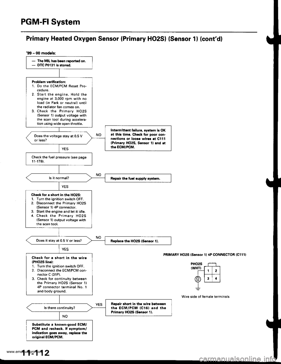
- The MIL has bsen reported on.- DTC P0131 ir storod.
Problem ve fication:1. Do the ECM/PCM Reset Pro-cedure,2. Start the engine. Hold theengine at 3,000 rpm with noload {in Park or neutral) untillhe radiator tan comes on.3. Check the Primary HO2S(Sensor 1) oltput voltage withthe scan tool during accelera-tion using wide op€n throttle.
Inl.rmittant failura, 3yrtam i! OKat thb tim.. Ch.ck tor poor con-nectiona oa looaa wlraa al C111{Pri|n.ry HO2S, Son3or 1l .nd .ttho ECM/FCM,
Does the voltage stay at 0.5 Vor less?
Check tho fuel pressure (see pago1r,178).
R.p.ir th. fu€l lupply ry!t.m.
Chock lor a short in tho HO2S:1. Turn the ignition switch OFF.2. Disconnect the Primary HO2S(Sensor 1) 4P connector.3. St6rt the engine and lot it idle.4. Check the Primary HO2S(Sensor 1) output voltage withthe scan tool,
Does it stay 6t 0.5 V or less?Rephc. th6 HO2S (S.n3or 11.
Chock for a short in tho wirc(PHO2S lino):1. Turn the ignition switch OFF.2. Disconnect the ECM/PCM con-nector C (31P).
3. Check tor continlity betweenthe Primary HO2S {Sensor 'l}
4P connector terminal No. Iand body ground.
Ragah rhort in tha wira balwoanth. ECM/PCM {Cl61 rnd thcPrirn.ry HO2S (S.n3or 11.
Substltut6 a known-good ECM/PCM and recheck. lf rymptom/indicrtion 00os away, raplaco thcoriginal ECM/PCM.
Primary Heated Oxygen Sensor (Primary HO2SI (Sensor 1l (cont'd)
PRIMARY HO2S (Son.or 1l aP CONNECTOR |C111)
PHO2S T--1rwHTr f-T---]
--1 1 2lI t--- 1t6)lslrlv L__r__J
_L
Wire side ol female terminals
11-112
www.emanualpro.com
Page 320 of 1395
PGM-FI System
Secondary Heated Oxygen Sensor (Secondary HO2SI (Sensor 2l (cont'dl
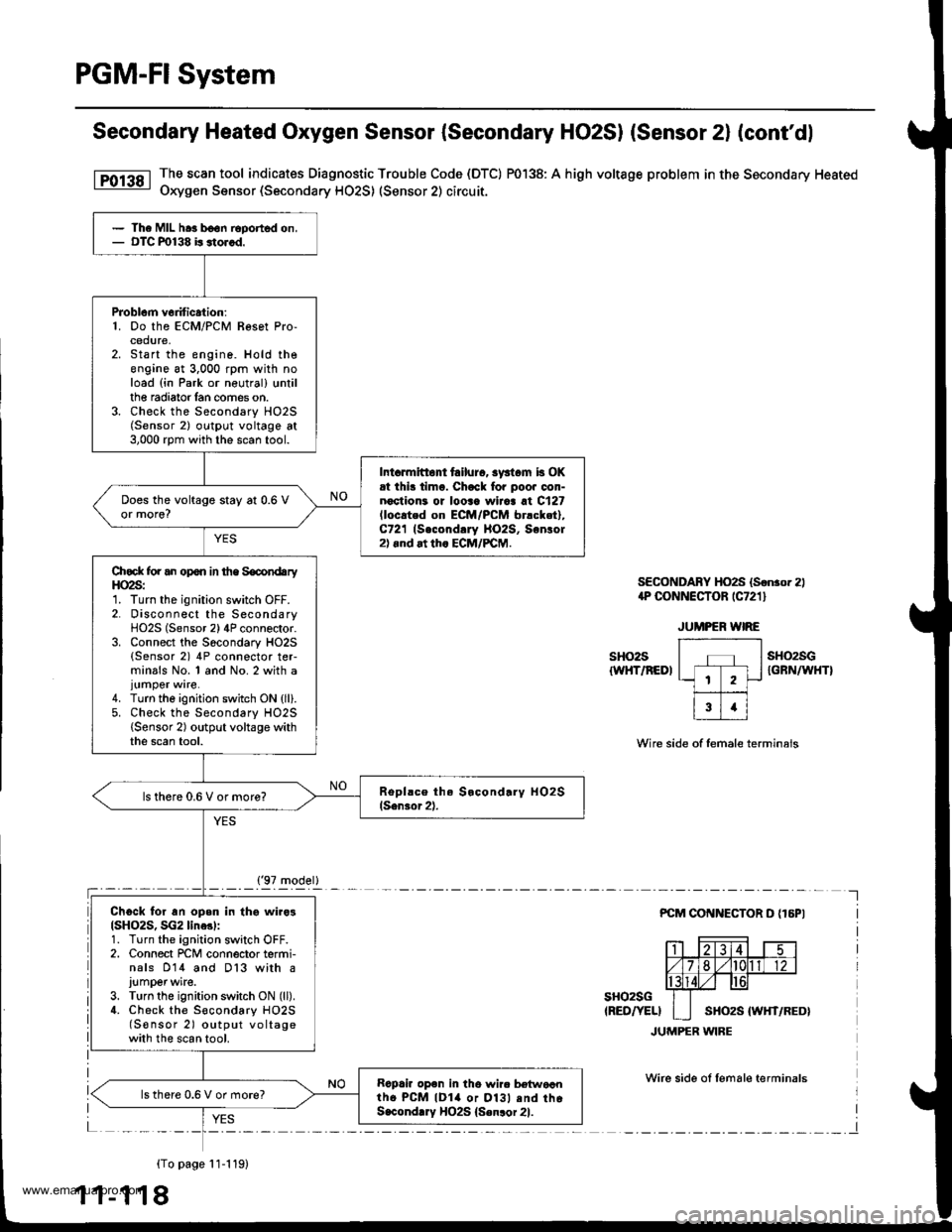
The scan tool indicates Diagnostic Trouble Code (DTC) P0138: A high voltage problem in the Secondary Heated
Oxygen Sensor (Secondary HO2S) (Sensor 2) circuit.
SECONDABY HO2S (Sonror 2)1P CONNECTOR rC721 l
sHo2s{WHT/REDI
sH()2sGIGFN/WHTI
Wire side of female terminals
PCM COI{NECTOR D {16PI
sHo2sG(RED/YELI
JUMPER WIRE
Wirc side ol lemale terminals
{To page 11-119)
1 1-1 18
The MIL hra b€on Eported on,OTC m138 b stor.d.
PJoblcm v6dtic.tion:1. Do the ECM/PCM Resot Pro-cedure,Start the engine. Hold theengine at 3,000 rpm with noload (in Park or neutral) trntilthe radiator lan comes on.Check the Secondary HO2S(Sensor 2) outpl.rt voltage at3,000 rpm with the scan tool.
Int.rmitto tailurc, syst.m b OKrt ihi! timo. Chack fo. poo. oon-noctioni or looaa wiiaa at C127lloc.ted on EcM/PcM br.cket),C721 (Second!ry llO2S, Sonlol2).nd at th. ECM/PCM.
Does the voltage stay at 0.6 Vor more?
Chock for an opon in the SocondaryHO2S:1. Turn the ignition switch OFF.2. Disconnect the SecondaryHO2S (Sensor 2) 4P connector.3. Connect the Socondary HO2S(Sensor 2) 4P connector ter-minals No. 1 and No. 2 with a
4. Turn the ignition switch ON {ll}.5. Check the Secondary HO2S{Sensor 2) output voltage withthe scan tool.
ls there 0.6 V or more?
Ch6ck for an open in thg wiro3(SH()2S, SG2 line3l:1. Turn the ignition switch OFF.2. Connect rcM connector termi-nals 014 and D13 with a
J!mper wite.3. Turn the ignition switch ON (ll).
4. Check the S€condary HO2S(S€nsor 2) output voltagewith the scan tool.
Rapair op6n in tho wir. b€{woantho PcM lDla or Dl3l .nd thoS.condlry HO2S {Senlor 21.
lsthere 0.6 V or more?
('97 model)
www.emanualpro.com
Page 332 of 1395
PGM-FI System
Knock Sensor {KSl
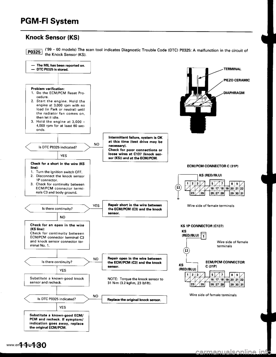
('99 - 00 models) The scan tool indicates Diagnostic Troublo Code (DTC) P0325: A malfunction in the circuit ofthe Knock Sensor (KS).
ECM/PCM CONNECTOR C 131P}
Wire side of female terminals
KS 1P CONNECTOR IC13?'
KSIRED/BLU)
KS(BED/BLU)
Wire side ol femaletermtnals
ECM/PCM CONNECTORc (31P)
- The MIL has been rooorted on.- DTC m325 is storod.
Problem verification:1. Do the ECM/PCir, Reset Procedure,2. Start the engine. Hold theengine at 3,000 rpm with noload (in Park or neutral) untilthe radiator tan comes on,then let it idle.3. Hold the engine at 3,000 -
4,000 rpm for at least 60 sec-onds,
Intermittent lailu.e, 3ystom is OKat thi3 tim. (te3t drive m.y benacalLrYr.Chock to. poor connsctions olloora wiros rt C137 lknock aon-.o. (KS)) and ar the ECM/FCM.
Ch€ck tor a short in the wir6 {KSlinel:1. Turn the ignition switch OFF.2, Disconnect the knock sensorlP connector.3. Check lor continuity betweenECM/PCM connector terminals C3 and body ground.
Replil rhort in the n irg b6{wocntho ECM/PCM lc:ll and the knocks€ngr1.
Check fo..n open in the wire{KS line):Check for continuity betweenECM/PCM connector terminal C3and knock sensor connector ter,minal No. 1.
B.pair opon in the wirc lrotweenlho ECM/PCM lctl and thc knockacnsor.
ls there cont;nuity?
Substitute a known-good knocksensor and recheck.
ls DTC P0325 indicated?Bcpl.ce the original knock 3€nsor,
Substituto a known-good ECM/PCM and .echeck. lf 3ymptom/indication goes away, replacethe original ECM/PCM.
NOTE: Torque the knock s6nsor to31 N.m (3.2 kgl.m, 23 lbf.ft).
1 1-130
Wire side ot female terminals
www.emanualpro.com
Page 337 of 1395
![HONDA CR-V 2000 RD1-RD3 / 1.G Workshop Manual
Vehicle Speed Sensor (VSSI
lPosoo-]-. |posol l-
97 modol:
The scan tool indicates Diagnostic Trouble Code {DTC} P0500*�or P0501*r: A range/perfor-
mance in the Vehicle Speed Sensor (VSS) circuit. HONDA CR-V 2000 RD1-RD3 / 1.G Workshop Manual
Vehicle Speed Sensor (VSSI
lPosoo-]-. |posol l-
97 modol:
The scan tool indicates Diagnostic Trouble Code {DTC} P0500*�or P0501*r: A range/perfor-
mance in the Vehicle Speed Sensor (VSS) circuit.](/manual-img/13/5778/w960_5778-336.png)
Vehicle Speed Sensor (VSSI
lPosoo-]-'. |posol l-'
'97 modol:
The scan tool indicates Diagnostic Trouble Code {DTC} P0500*'�or P0501*r: A range/perfor-
mance in the Vehicle Speed Sensor (VSS) circuit. * I ; A/T*2i Mfi
FCM CONNECTORS
A t32Pl
LG1(BRN/BLK)
NOTE: Do not use the engine to turn thofront wheels with th6 rear wheels on theground. The 4WD system will engage andthe vehicle will suddenlv Iurch forward.
Wire side ot female terminals
LGl
{BRN/BLKI
(cont'd)
11-135
The MIL hes boen roported on.DTC m501 is 3tor€d.
Problom verificetion:1. Test'drive the vohicle.2. Check the vehicle speed withthe scan tool,
lntormittent tailure, rystom b OKat thia timo. Chock tor poor con-nection3 or 10o3o wires rt C129lvss) .nd rr rhe Pcfr4,
ls the correct speed indicated?
Chock for an open in tho PiCM:1. Turn the ignition switch OFF.2. Block the rear wheels and setthe parking brake.3. Jack up the lront of the vehicleand support it with saletystands.4. Turn the ignition switch ON (ll).
5. Elock the right front wheel andslowly rotate the left trontwheel by hand.6. Measure voltage betweenPCM connector terminals C18and A9.
Substitulc a known-good PCMand .och6ck. It symptom/indicd.tion go.a away, .cplaco tho origi-nel FCM.
Doesthe voltage pulse 0 Vand 5 V or battery voltage?
Check for a .hort in the PCM:L Turn the ignition switch OFF.2. Disconnect the PCM con'nector C (31P).
3. Turn the ignition switch ON (ll).
4. Elock the right front wheeland slowly rotate the left front
5. Measure vohage between PCMconnector terminals C18 andA9.
Substituto e known-good PCMand rochock. f rymptom/indica-tion goos rwry, roplsc. tho origi-nalFCM.
Doesthe voltage pulse 0 Vand 5 V or battery voltage?
- Repair short in the wirebetween the PCM lC18l,cruise control unit, speodo-meter, and VSS,- Repair opon in the wirebetween the PCM {C181 .ndrhe vss.- f wire is OK. tost lho VSS l3oosoction 231.
www.emanualpro.com
Page 338 of 1395
PGM-FI System
Vehicle Speed Sensor (VSSI {cont'd}
'98 - 00 models:
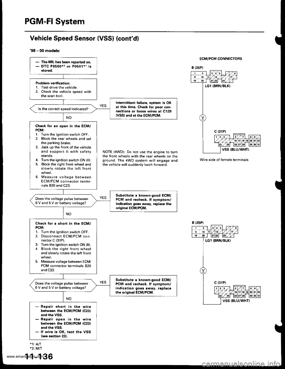
ECM/PCM CONNECTORS
B t25Pl
NOTE (4WD): Do not use the engine to turnthe front wheels with the rear wheels on theground. The 4WD system will engage andthe vehicle will suddenly lurch forward.
Wire side of female terminals
- The MIL ha3 been reDoned on.- DTC P0500" or P0501*1 i33torod.
Probl6m verification:1. Test-drive the vehicle.2. Check the vehicle speed withthe scan tool,
Intermittont failu.e, svstem is OKat thk time. Check for poor con-nection! or loose wiros at C129lvss) .nd ar the EcM/PcM.
ls the correct speed indicated?
Check for rn open in the ECM/PCM:l� Turn the ignition switch OFF.2. Elock the rear wheels and setthe parking brake.3. Jack up the front oI the vehicleand support it with satetystands.4. Turn the ignition switch ON {ll}.5. Block the right front whoel andslowly rotate the lett front
6. Measure voltage betweenECM/PCM connector termi-nals 820 and C23.
Substitute a known-good ECM/PCM and rochock. ll symptom/indicetion 9063 away, .oplace th€origin.l ECM/PCM.
Does the voltage pulse between0 V and 5 V or battery voltage?
Check for a short in the ECM/PCMI1. Turn the ignition switch OFF.2. Disconnect ECM/PCM connector C 131P).3. Turn the ignition swilch ON {ll).4. Block the right front wheeland slowly rotate the left front
5. Moasure voltage between ECM/PCM connector terminals 820and C23.
Sub.titute a known-good ECM/PCM and rschock. It rymptom/indication goos .w.y. replecerhe original ECM/PCM.
Does the voltage pulse betlveen0 V and 5 V or battery voltage?
- R.pair short in the wirobetwe€n the ECM/PCM lC23).nd tho VSS.- Roprir open in th6 wirebotweon the ECM/PCM lc23land th6 vss.- It wirc is OK, te3t ihe VSS(!€e soetion 23).
B (25P)
1
*2:Mft
1-136
www.emanualpro.com
Page 340 of 1395
PGM-FI System
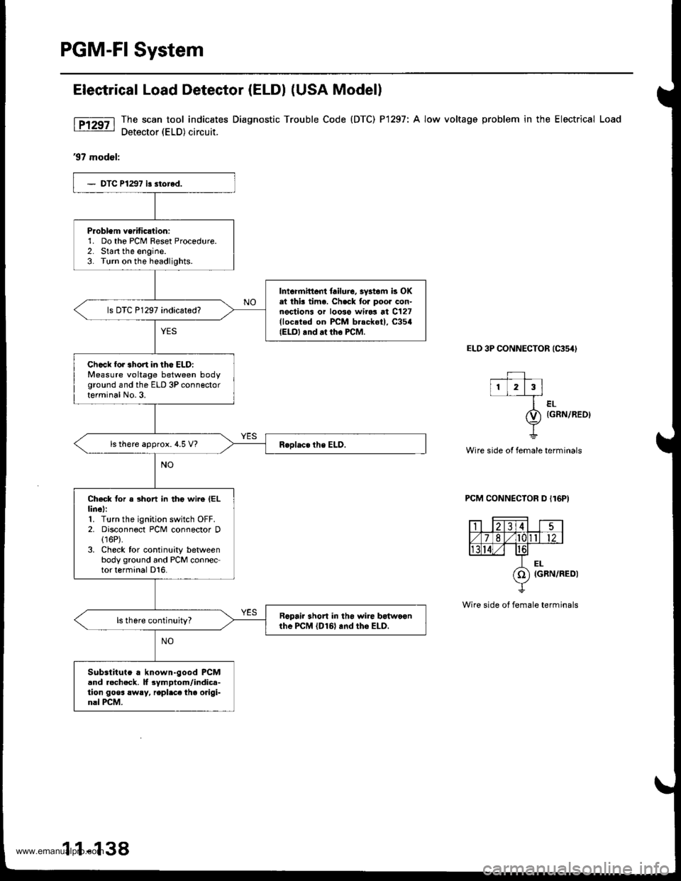
Elestrical Load Detector (ELDI (USA Modell
The scan tool indic€tes Diagnostic Trouble Code (DTC) P1297: A low voltage problem in the Electrical Load
Detector (ELD) circuit.
'97 model:
ELD 3P CONNECTOR {C354I
--+-l1L2l3l
ler-
O) tcnrulaeot
Y
Wire side ot female terminals
PCM CONNECTOR D I16P)
Wire side of female terminals
Problem vsriticltion:1. Do the PCM Feset Procedure.2. Start the engine.3. Turn on the headlights.
Intormittent lailuic, 3vstom k OKat thk time. Ch.ck tor poor con-nections or loose wiro3 at C127(loc.ted on PCM b.sckot), C354{ELO, .nd at tho FCM.
ls DTC P1297 indicated?
Ch.ck for 3hort in lho ELD:Measure voltage between bodyground and the ELD 3P connectorterminal No.3.
ls there approx. 4.5 V?
Check for a short in tho wire IELlinel:1. Turn the ignition switch OFF.2. Disconnect PCM connector D(16P).
3. Check for continuity betweenbody ground and PCM connector terminal D16.
Rcpair 3hort in tho $rire botwo€nthe PcM lDl6l and tho ELD.
Substituto a known-good PCMand rocheck. lf 3ymptom/indic.-tion goos !w!y, repl.ce the origi-nal PCM.
1 1-138
www.emanualpro.com
Page 342 of 1395
PGM-FI System
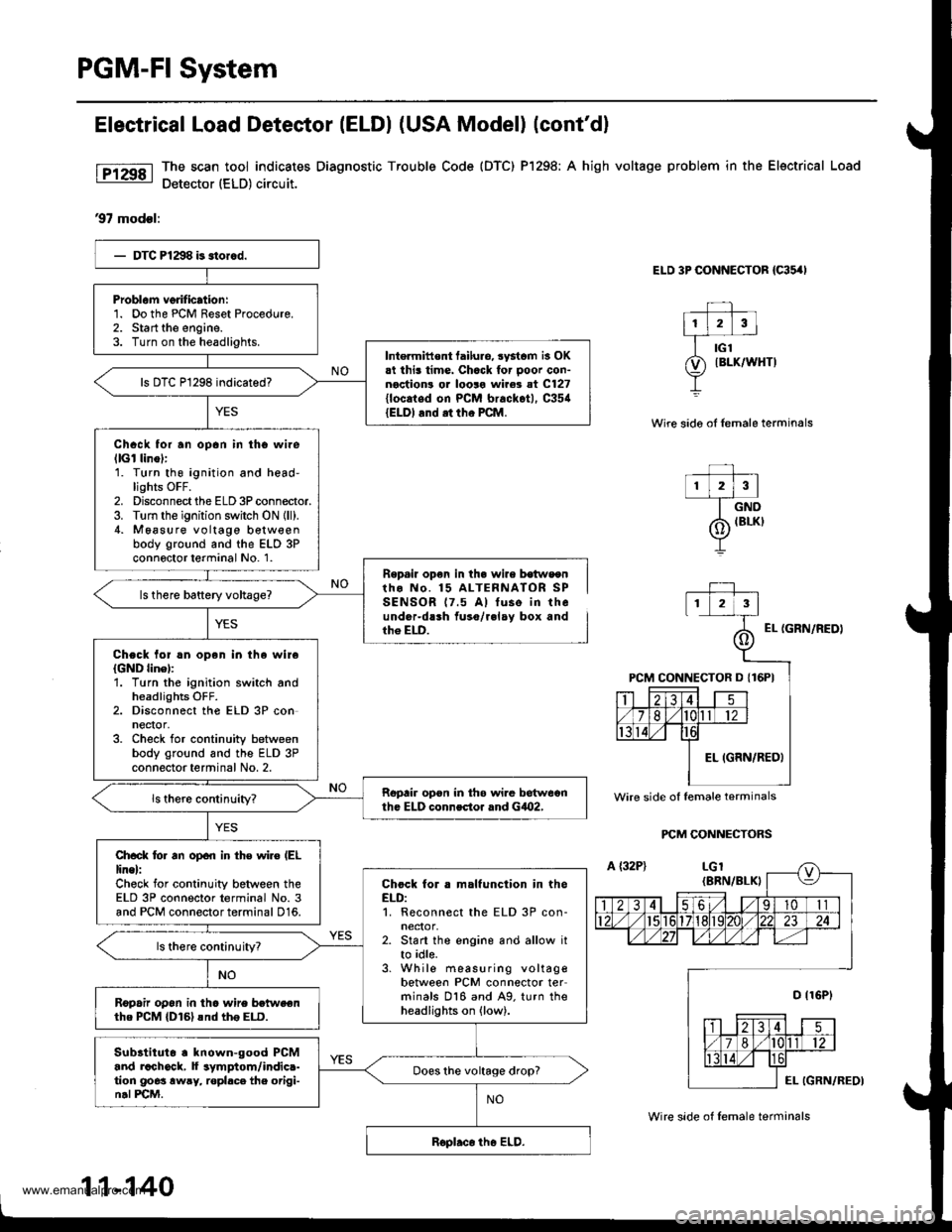
Electrical Load Detestor (ELDI (USA Model) (cont'dl
The scan tool indicates Diagnostic Trouble Code {DTC) Pl298; A high voltage problem in the Electrical Load
Detector (ELD) circuit.
97 modsl:
ELD 3P CONNECTOR {C35,'I
Wire sido oI lemale terminals
r lzlrl--T_ow
/6 IBLKI
Y
Repail op€n in th. wire b€tws€ntho No. 15 ALTERNATOR SPSENSOR 17.5 A) tuse in theunder-dlrh fuso/r.lay box andth6 ELD.EL {GRN/NEDI
PCM CONNECTORS
Problam verification:1. Do the PCM Reset Procedure.2. Start the engine.3. Turn on the headlights.Intermittent tailuro, systcm is OK.t this time. Chack for ooor con-noction! or looro wire3 at C127{locaied on PCM brackot), C35{{ELDI and .t tho PCM.
Chack for an opan in tho wilellGl linol:1. Turn thg ignition and head-lights OFF.2. Disconnect the ELD 3P connector.3. Turn the ignition switch ON {ll).4. M6asure voltage b€tw€enbody ground and the ELD 3Pconnoctor terminal No. 1.
Chock lol !n open in the wireIGND linel:'1. Turn the ignition switch andheadlights OFF.2. Disconnect the ELD 3P conneqor,3. Check for continuity betweenbody ground and the ELD 3Pconnector terminal No. 2.
Ropair opon in th6 wi.e betweonth. ELD connector rnd GiO2,
Ch.ck lo. an open in th€ wiro (EL
line):Check for continuity between theELD 3P connector terminal No. 3and PCM connector terminal 016.
Chock for . malfunction in theELD:1. Reconnect the ELD 3P con-neclor,2. Start the engine and allow itto idle.3. While measuring voltagebetween PCM connector terminals 016 and A9. turn theheadlights on (low).
ls there continuityT
R6pafu op6n in tho wire betweenthe PCM {D161snd th6 ELD.
Subltituto . known-good PCMand rachock, f symptom/indic.-tion goes awry, ropl.ce the origi-n.l PCM.
Does the voltage drop?
Wire side of lemale terminals
11-140
Wire side of lemale terminals
www.emanualpro.com