Page 421 of 1395
'98 - 00 mod€ls:
The scan tool indicates Diagnostic Trouble code (DTc) P1457: Evaporative Emission (EVAP) Control system leak
detected (EVAP control canister system).
Troubl6shooting Flowchart('98 model only)_]
I
- The MIL has been rePorted on.- DTC P1,157 is storod.
Do the fuel tank Pressure sensor
test {see page 11-214).
ls the {ueltank pressure sensor OK?
Do the EVAP Purge contlol
solenoid valve test lsea Page 1l_
220t.
(cont'dl
11-219
www.emanualpro.com
Page 423 of 1395

EVAP bypass solenoid valv€ test.
{The continuation of DTC P1457
troubleshooting.l
Check the EVAP bypass 3olenoid
1. Disconnect the vacuLlm hose
from the EVAP two way valve,
and conned a vacuum PUmPto the hose.2. Turn the ignition switch ON (ll).
3. Apply vacuum to the hose
EVAP bvpas3 30lsnoid vrlvo/
EVAP two way v.lve is OK. Do
the EVAP control canisler vent
3hut v.lve te3l (see Psge11'2221.
Does the valve hold vacuum?
Ch6ck the EVAP byp.ss solenoid
'1. Turn the ignition switch OFF
2. Disconnect the EVAP bypass
solenoid valve 2P connector.
3. Check {or continuity between
the EVAP bypass soleno id
valve 2P connector termlnal
No. 2 and body ground
ReDlace the EVAP bypass 3olenoid
valve and O-rings.
Check for a short in lhe wire
{2WBS linel:1. Disconnect ECM/PCM connec
tor A (32P).
2. Check lor continuity betlveenthe EVAP bypass soleno id
valve 2P connector termrnalNo. 2 and body ground.
Rcpsir short in th. wire bgtwoen
the EcM/PCtrl lA3l lnd the EVAP
bypa$ solenoid valvo.ls there continuitY?
Sub3tiiute . known'good ECM/
PCM End recheck. lI sYmptom/
indication goe3 away, tePlace
the original ECM/PCM.
EVAPBYPASSFUELTANKPRESSUBE SENSORSOLENOIDVALVEEVAP TWO WAY
VALVE
VACUUMPUMP/GAUGE,0-30 in.HgA973X -
041 -
xxxxx
EVAP AYPASS SOLENOID
VALVE 2P CONNECTOR (C647}
q
@)
T
t.'-+lt1t?l
| 2wBs
(d1 terul
Y-L
Wire side offemaleterminals
2WBS(BLU}
(cont'd)
11-221
www.emanualpro.com
Page 426 of 1395

Emission Control System
Evaporative Emission (EVAP) Controls (cont,dl
Evaporative Emission (EVAP) Two Way Valve Testing
'97 model:
1. Remove the fuelfill cap.
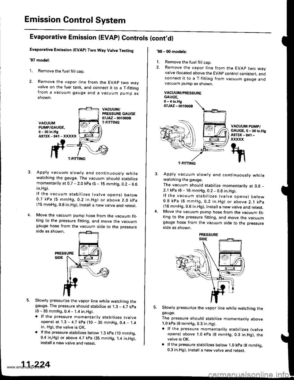
2. Remove the vapor Iine from the EVAP two wayvalve on the fuel tank, and connect it to a T_fittingfrom a vacuum gauge and a vacuum pump asshown.
VACUUM,/PRESSURE GAUGEotJAz - 001 rDoBT-FITTINGVACUUMPUMP/GAUGE,0 - 30 in.HgA973X-041-XXXXX
3. Apply vacuum slowly and continuouslv whilewatching the gauge. The vacuum should stabilizemomentarily at 0.7 - 2.0 kpa (5 - 1S mmHg, 0.2 _ 0.6in.Hg).
lf the vacuum stabilizes (valve opens) below0.7 kPa (5 mmHg,0.2 in,Hg) or above 2.0 kpa(15 mmHg, 0.6 in.Hg), install a new valve and retest.
4.Move the vacuum pump hose from the vacuum fit_ting to the pressure fitting, and move the vacuumgauge hose from the vacuum side to the pressureside as shown.
PiESSURESIDE
5. Slowly pressurize the vapor line while watching thegauge. The pressure should stabilize at 1.3 - 4.7 kpa(0 - 35 mmHg, 0.4 - 1.4 in.Hg).. lf the pressure momentarily stabilizes (valve
opens) at 1.3 - 4.7 kpa (10 - 35 mmHg, 0.4 _ 1.4in. Hg), the valve is OK.. lf th6 pressure stabilizes below 1.3 kpa fio mmHg,0.4 inrHg) or above 4.7 kpa (35 mmHg, 1.4 in.Hg),install a new valve and retest.
T-FITTING
11-224
.98 - 0O models:
1. Remove the fuel fill cap.2. Remove the vapor line from the EVAP two wayvalve {located above the EVAP control canister). andconnect it to a T-fitting from vacuum gauge andvacuum pump as shown.
VACUUM/PRESSUFE
VACUUM PUMP/GAUGE,0 - 30 in.HgA973X - 041 -
xxxxx
5.
Apply vacuum slowly and continuously whilewatching the gauge.
The vacuum should stabilize momentarily at O.g _
2.1 kPa (6 - 16 mmHg, 0.2 - 0.6 in.Hg).lf the vacuum stabilizes (valve opens) below0.8 kPa (6 mmHg, 0.2 in.Hg) or above 2.1 kpa(16 mmHg, 0.6 in.Hg), install a new valve and retest.Move the vacuum pump hose from the vacuum fit-ting to the pressure fitting. and move the vacuumgauge hose from the vacuum side to the pressure
side as shown.
Slowly pressurize the vapor line while watching thegauge.
The pressure should stabilize momentarilv above1.0 kPa (8 mmHg, 0.3 in.Hg).a lf the pressure momentarily stabilizes (valve
opens) above 1.0 kPa (8 mmHg. 0.3 in.Hg), thevalve is OK.. lf the pressure stabilizes below ,|.0 kpa {g mmHg.0.3 in.Hg), install a new valve and retest.
T-FITTING
www.emanualpro.com
Page 436 of 1395

Flywheel
Inspection
2.
3.
Llnspect the ring gear teeth for wear and damage.
Inspect the clutch disc mating surface on the fly-
wheel for wear, cracks, and burning
Measure the flywheel runout using a dial indicator
through at least two full turns. Push against the fly-
wheel each time you turn it to take up the crank-
shaft thrust washer clearance.
NOTE: The runout can be measured with engine
installed.
Standard (Newl: 0.05 mm (0.002 in) max.
Service Limit: 0.15 mm {0.006 inl
lf the runout is more than the service limit, replace
the flywheel and recheck the runout
Turn the inner race ot the flywheel bearing with your
finger. The bearing should turn smoothly and qui-
etly. Check that the bearing outer race fits tightly in
the tlywheel. lf the race does not turn smoothly, qui-
etly, or fit tight in the flywheel, replace the bearing.
FLYWHEEL
RING GEAR
FLYWHEEL
L
2.
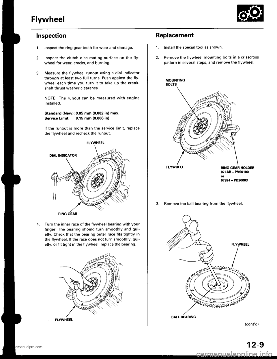
Replacement
Installthe special tool as shown.
Remove the flywheel mounting bolts in a crisscross
pattern in several steps, and remove the flywheel.
MOUNNNGBOLTS
FLYWHEEL
(cont'd)
12-9
RING GEAR HOLDER07LAB - PV00r00ol07924 - PD20003
3. Remove the ball bearing from the flywheel.
BALL BEARING
www.emanualpro.com
Page 443 of 1395

Transfer Assembly
lnspection
@ Make sure tifts, iacks, and satety stands
are placed properly (see section 1).
L Raise the front of the vehicle, and support it with
safety stands (see section 1).
2. Set the parking brake, and block both rear wheels
securely.
3. Shift to neutral oosition.
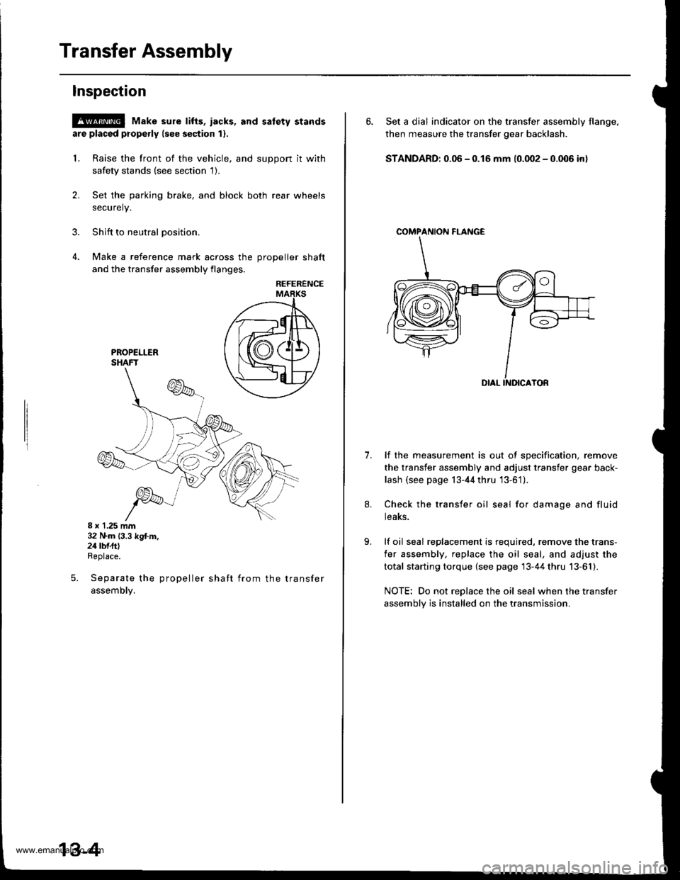
4. Make a reference mark across the DroDeller shaft
and the transfer assembly flanges,
REFERENCE
8 x 1.25 mm32 N.m (3.3 kg{.m.24 rbf.ftlReplace.
Separate the propeller shaft from the transfer
assemDty.
5.
13-4
6. Set a dial indicator on the transfer assembly flange,
then measure the transfer gear backlash.
STANDARD: 0.06 - 0.16 mm (0.002 - 0.006 in)
COMPAf{ION FI-ANGE
1.lf the measurement is out of specification, remove
the transfer assembly and adjust transfer gear back-
lash (see page 13-44 thru '13-61).
Check the transfer oil seal for damage and fluid
teaKs.
lf oil seal replacement is required, remove the trans-
fer assembly, replace the oil seal, and adjust the
total starting torque (see page 13-44 thru 13-61).
NOTE: Do not replace the oil seal when the transfer
assembly is installed on the transmission.
www.emanualpro.com
Page 462 of 1395

Mainshaft Assembly
lndex
Note the Iollowing during reassembly:
. The 3rd/4th, and 5th synchro hubs, and the ball bearing are installed with a press.
. Installthe angular ball bearing with the thin-edged outer race facing the stop ring
prior to reassembling, clean all the parts in solvent, dry them, and apply lubricant to any contact surfaces. The
3rd/4th and 5th svnchro hubs, however, should be installed with a press before lubricating them'
ANGULAR EALL BEARINGCheck for wear and operation.Note the directionof installation.SYNCHRO RINGInspection, page l3 37
SYNCHRO HUBlnspection, page 13-36
SYNCHRO SLEEVEInspection, page 13 36
SPRING
SYNCHRO
SYOP RING
TAPER RING
BEARINGCheck Ior wear and operataon.
COLLAR
RINGInspection, page 13-37
SYNCHRO SPRING
SYNCHRO HUBInspection, page 13_36
SYNCHRO SLEEVEInspection, page 13 36
SPFING
RINGInspection, page 13_37
GEARInspection, page 13_25, 37
COLLARInspection, page 13-24, 25
GEARInspection, page 13 24, 37
Inspection,page 13-37
3RD GEARInspeclton,page 13 24,37
BEARINGCheck for wearano operalton.
Inspection, page 13 26
NEEDLE BEARINGCheck for wear and operat,on.
13-23
www.emanualpro.com
Page 467 of 1395
Countershaft Assembly
Index
NOTE:
3
The 3rd, 4th. and sth gear are installed with a press.
Prior to reassembling, clean all the parts in solvent, dry them, and apply lubricant to any contact surfaces. The 3rd,
4th, and sth gears, however. should be installed with a press before lubricating them.
LOCKNUT Replace.127-o-127N.m
113-0- 13kstmi
\94-0- 9.trbtft /
IST/2ND SYNCHRO HUBInspection, page 13 36
Check lor wear anddamage.
THRUST WASHERInspection, page 13-29
DAMPER
WASHER
AEARINGCheck for wear and ooeration.
BEARINGCheck for wear andoperation.
GEAR
4TH GEAR
3RD GEAR
GEAR
SPNING
DOUBI.f CONE
Inspection, page 13-37
1ST GEARInspection, page 13 29,37
BEARINGCheck tor wear and operation.
Inspection, page 13-30, 37
NEEDLE BEARINGCheck for wear and oPeration
SPACERSelection, page 13-30
DAMPERCheck for wear and damage.
DOUBLE CONE
Inspection, page 13-37
SPRING
www.emanualpro.com
Page 472 of 1395
Reassembly
Note these items during reassembly:
. Press the 3rd, 4th, and sth gear on the countershaft
without lubrication.
. When installing the 3rd, 4th. and sth gears, suppon
the shaft on steel blocks and install the gears using a
press.
. Refer to page 13-28 for reassembly sequence.
1. Install the thrust shim, needle bearing, 1st gear, and
friction damper.
NOTE: Reassembly the friction damper on the lst
gear before installation.
rnrcrroru orn,leen ----.-4O)
lST GEAR
NEEDLE BEARING
THRUST SHIM
2. Install the double cone synchro.
3. Install the 1sv2nd synchro hub by align the friction
damper fingers with 1svznd synchro hub grooves.
(cont'd)
OUTER
lST/2ND
13-33
www.emanualpro.com