Page 520 of 1395

Description
General Operation (cont'dl
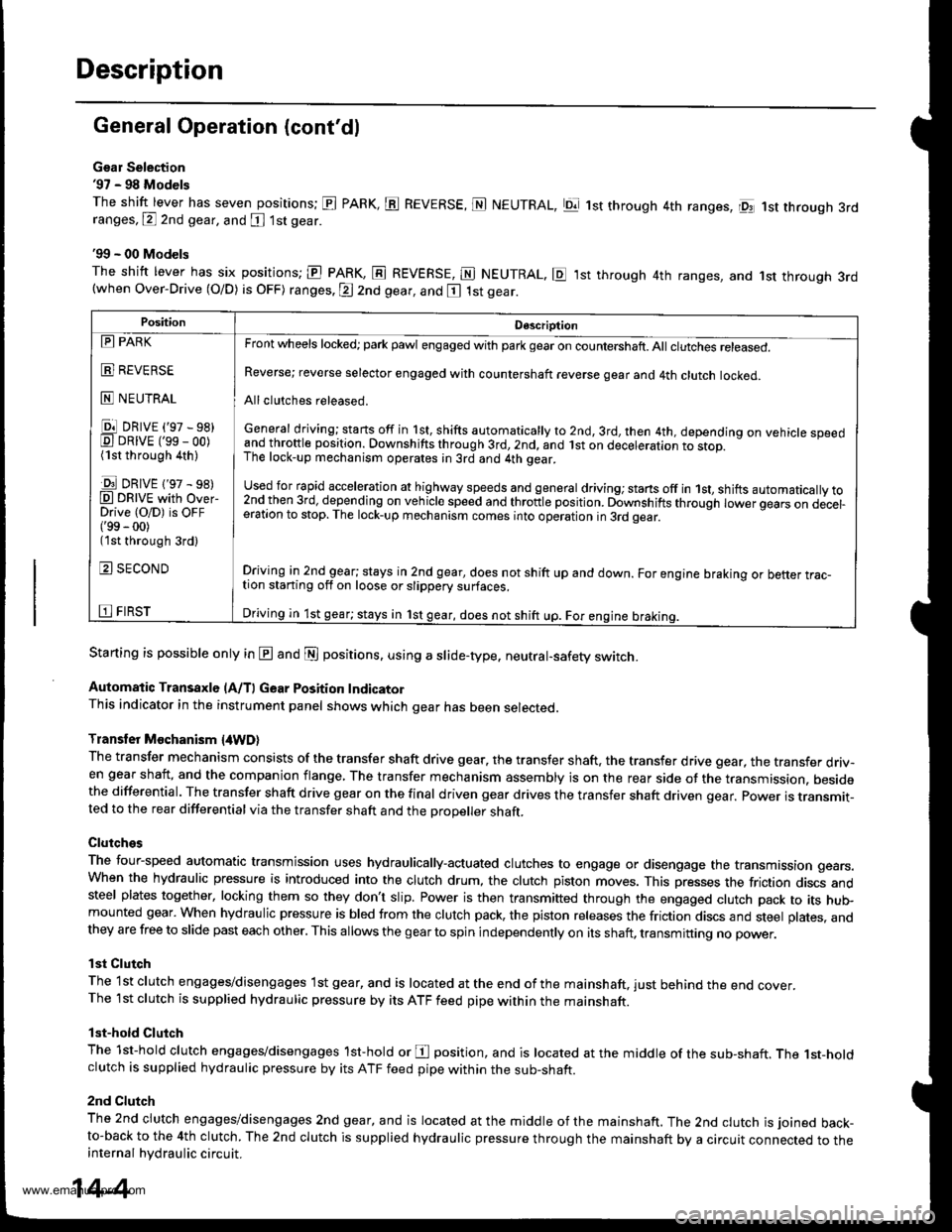
Gsar Selection'97 - 98 Models
The shift lever has seven positions; El PARK, ts REVERSE, N NEUTRAL, Ell 1st through 4th ranges, lpq 1st th.ough 3rdranges, P 2nd gear, and [ 1st gear
'99 - 00 Models
The shitt lever has six positions; El PARK, E REVERSE, E NEUTRAL. E ,lst through 4th ranges, and 1st through 3rd(when Over-Drive (O/D) is OFF) ranges. @ 2nd gear, and E 1st gear.
Starting is possible only in @ and @ positions. using a slide-type. neutral-safety switch.
Automatic Transaxle (A/T) Gear Position IndicatorThis indicator in the instrument panel shows which gear has been selected.
Transler Mochanism {4WD}
The transfer mechanism consists of the transfer shaft drive gear. the transfer shaft. the transfer drive gear, the transfer driv-en gear shaft, and the companion flange, The transfer mechanism assembly is on the rear side ot the transmission. besidethe differential. The transfer shaft drive gear on the final driven gear drives the transfer shaft driven qear. power is transmit-ted to the rear differential via the transfer shaft and the Drooeller shaft.
Clutches
The four-speed automatic transmission uses hydraulically-actuated clutches to engage or disengage the transmission gears.When the hydraulic pressure is introduced into the clutch drum, the clutch piston moves. This presses the friction discs andsteel plates together, locking them so they don't slip. Power is then transmifted through the engaged clutch pack to its hu$mounted gear. When hydraulic pressure is bled from the clutch pack, the piston releases the friction discs and steel plates, andthey are free to slide past each other. This allows the gearto spin independently on its shaft, transmitting no power.
lst Clutch
The 1st clutch engages/disengages lst gear, and is located at the end ofthe mainshaft, just behind the end cover.The 1st clutch is supplied hydraulic pressure by its ATF feed pipe within the mainshaft.
lst-hold Clutch
The 1st-hold clutch engages/disengages 1st-hold or E position, and is located at the middle of the sub-shaft. The 1st-holdclutch is supplied hydraulic pressure by its ATF feed pipe within the sub-shaft.
2nd Clutch
The znd ciutch engages/disengages 2nd gear, and is located at the middle of the mainshaft. The 2nd clutch is joined back-to-back to the 4th clutch. The 2nd clutch is supplied hydraulic pressure through the mainshaft by a circuit connected to theinternal hydraulic circuit.
PositionDescription
Reverse; reverse selector engaged with countershaft reverse gear and 4th clutch locked.
Allclutches released.
General driving; starts off in 1st, shifts automatically to 2nd, 3rd, then 4th, depending on vehicle speedand throftle position. Downshifts through 3rd,2nd, and lst on deceleration to stop.The lock-up mechanism operates;n 3rd and 4th gear.
used for rapid €cceleration at highway speeds and general driving; stans off in 1st, shifts automatically to2nd_then 3rd, dejending on vehicle speed and throttle position. Downshifts through lower gears on decel-eration to stop. The lock-up mechanism comes into operation in 3rd gear.
Driving in 2nd_gear; stays in 2nd gear, does not shift up and down. For engine braking or better trac_tion starting off on loose or slippery surfaces.
Driving in 1st gear; stays in 1st gear, does not shift up. For engine braking.
tll PARK
t!!l l|EvEn>E
E NEUTRAL
Ell DRrvE ('97 - sB)E DRrvE ('ss - oo)(1st through 4th )
E DRrvE {'97 - s8)O DRTVE with over-Drive (O/D) is OFF('99 - 00)(1st through 3rd)
E SECOND
E FIRST
14-4
www.emanualpro.com
Page 530 of 1395

Description
Power Flow (cont'dl
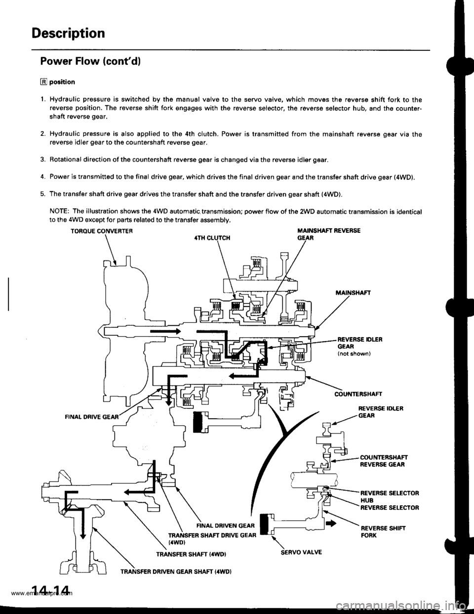
E position
1. Hydraulic pressure is switched by the manual valve to the servo valve, which movss the reverse shift fork to the
reverse position, The reverse shift fork engages with the reverse selector, the reverse selector hub, and the counter-
shaft reverse gear.
2. Hydraulic pressure is also applied to the 4th clutch. Power is transmitted from the mainshaft reverse gear via the
reverse idler gear to the countershaft reverse gear.
3. Rotational direction ofthe countershaft reverse gear ischanged viathe reverse idlergear.
4. Power is transmitted to the final drivegear,which drivesthefinal d riven gear a nd the transfer shaft drive gesr (4WD).
5. The transfer shaft drive gear drives the transfer shaft and the transfer driven gear shaft (4WD).
NOTE: The illustration shows the 4WD automatic.transmission; power flow of the 2wD automatic transmission is identical
to the 4WD except for parts related to the transfer assembly.
TOROUE CONVERTERMAINSHAFT REVERSE
COUNTERSHAFT
FINAL ORIVE
REVERSE IDLERGEAR
COUNTERSHAFTREVERSE GEAR
REVERSE SEITCTORHUBREVERSE SELECTOR
REVEBSC SHIFTFORK
FINAL OBIVEN GEAR
TRANSFER SHAFT DRIVE GEAR{4WD)
TRANSFER SHAFT {4WD)SERVO VAI-VE
14-14
TRANSFER DRIVEN GEAR SHAFT I4WD}
www.emanualpro.com
Page 532 of 1395
Description
PCM
PGM.FIControl System
Throttle Position SensorSignelVehicle Speed SensorSignal
Engin€ Coolsnt TomperatureSen30r SignalService Ch€ck Connectol
A/T Control Svstem
INTERLOCK
Shift Control
Shift ConlrolSolenoid Valve ACONTROL UNITr
RShift ControlSolenoid Valve B
N
Linear SolenoidD
Lock-up Control
2
Lock-up ControlSolenoid valve A1
Lock-up ControlSolenoid Valve BOver-DriveSwitch Signal
Mainshaft Speed SensorSignalE Indicator Light
Countershaft SpeedSensor SigntlSelt-Oiagnosis SigndSelf-DiagnosisFunc{ion
O/D OFFIndicetor Light
Electronic Gontrol System (cont'd)
'99 - 00 Models
14-16
www.emanualpro.com
Page 534 of 1395
Description
Electronic Control System (cont'dl
Grade Logic Control System
How it works:
The PCM compares actual driving conditions with memorized driving conditions, based on the input from the vehicle speed
sensor, the throttle position sensor, the barometric pressure sensor ('98 model). the engine coolant temperature sensor, the
brake switch signal, and the shift lever position signal, to control shifting while the vehicle is ascending or descending a
slope, or reducing speed.
SIGNALS DETECTED
Driving Rcsisl.nce
Judgemont ot Controlling Aroa
. Normal Modo {Flrt ro.d mode}. Ascending Mode. Deacending Mode. Deceleration Mode
14-14
www.emanualpro.com
Page 537 of 1395
Circuit Diagram and Terminal Locationsr9T Model
IGNITIONSWITCH
LOC( UPCONTROL
LOCK UPCONTROLSOLEITOIDVALVE B
sf Frc0|lltF0LSOLENOIDVALVE A
sHrFr c0r{TnoLSOLEI{OID VALVE B
UNEASSOLINOID
14-21
www.emanualpro.com
Page 541 of 1395
Main Valve Sody
The main valve body houses the manual valve, the 1-2 shift valve. the 2nd orifice control valve. the CPB valve, the modu-
lator valve. the servo control valve. and the relief valve. The primary functions of the main valve body are to switch fluid
pressure on and off, and to control the hydraulic pressure going to the hydraulic control system.
CP8 VALVE2ND ORIFICE CONTROLVALVE
MODULATOR VALVE
RELIEF VALVE
1-2 SHIFT VALVE
MANUAL VALVE
MAIN VALVEBOOY
SERVO CONTROI-VALVE
Secondary valve Body
The secondary valve body is located on the main valve body, The secondary valve body houses the 2-3 shift valve, the 3-4
shift valve, the 3-4 orifice control valve, the 4th exhaust valve, and the CPC valve'
3.' SHIFT VALVE
.TH EXHAUST VALVE
CPC VAL
(cont'd)
14-25
2.3 SHIFT VALVE
3na ORIFICE CONTROLVALVE
VALVE
www.emanualpro.com
Page 555 of 1395

Lock-up System
TOROUE CONVERTER
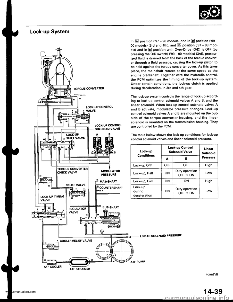
In E position ('97 - 98 models) and in E position ('99 -
OO models) (3rd and 4th), and E position ('97 - 98 mod-
els) and in E position with Over-Drive (O/D) is OFF (by
pressing the O/D switch) ('99 - 00 models) (3rd), pressur-
ized fluid is drained from the back of the torque convert-
er through a fluid passage, causing the lock-up piston to
be held against the torque converter cover, As this takes
Dlace, the mainshaft rotates at the same speed as th8
engine crankshaft. Together with the hydraulic control,
the PCM optimizes the timing of the lock-up system.
Under certain condltions. the lock-up clutch is appli€d
during deceleration, in 3rd and 4th gear.
The lock-up system controls the range of lock-up sccord-
ing to lock-up control solenoid valves A and B, and ths
linear solenoid. When lock-up control solenoid valves A
and B activate. modulator pressure changes. Lock-up
control solenoid valves A and B are mounted on the out-
side of the torque converter housing, and the linear
solenoid is mounted on the transmission housing. They
are controlled bv the PCM.
The table below shows the lock-up conditions for lock-up
control solenoid valves and linear solenoid pressure.
LINEAR SOLENOID PRESSURE
(cont'd)
LOCK.UP CONTROL' VALVE
LOCK.UP CONTROLSOLENOID VALVE
AB
MODULATORPf,ESSURE
MAINSHAFT
COUNTERSHAFT
SUB.SHAFT
Lock-up
Conditions
Lock-up Conirol
Solenoid valveLinaal
Solenoid
PrgssulsAB
Lock-up OFFOFFOFFHigh
Lock-up, HalfONDuty operation
OFF - ONLow
Lock-up, FullONONHigh
Lock-up
during
deceleration
ONDuty operation
OFF - ON
RELIEF VALVE
LOCK'UP TIMINGVALVE
COOLER RELIEF VALVE
ATF COOLERATF STRAINER
ATF PUMP
14-39
www.emanualpro.com
Page 558 of 1395

Description
Lock-up System (cont'dl
a
a
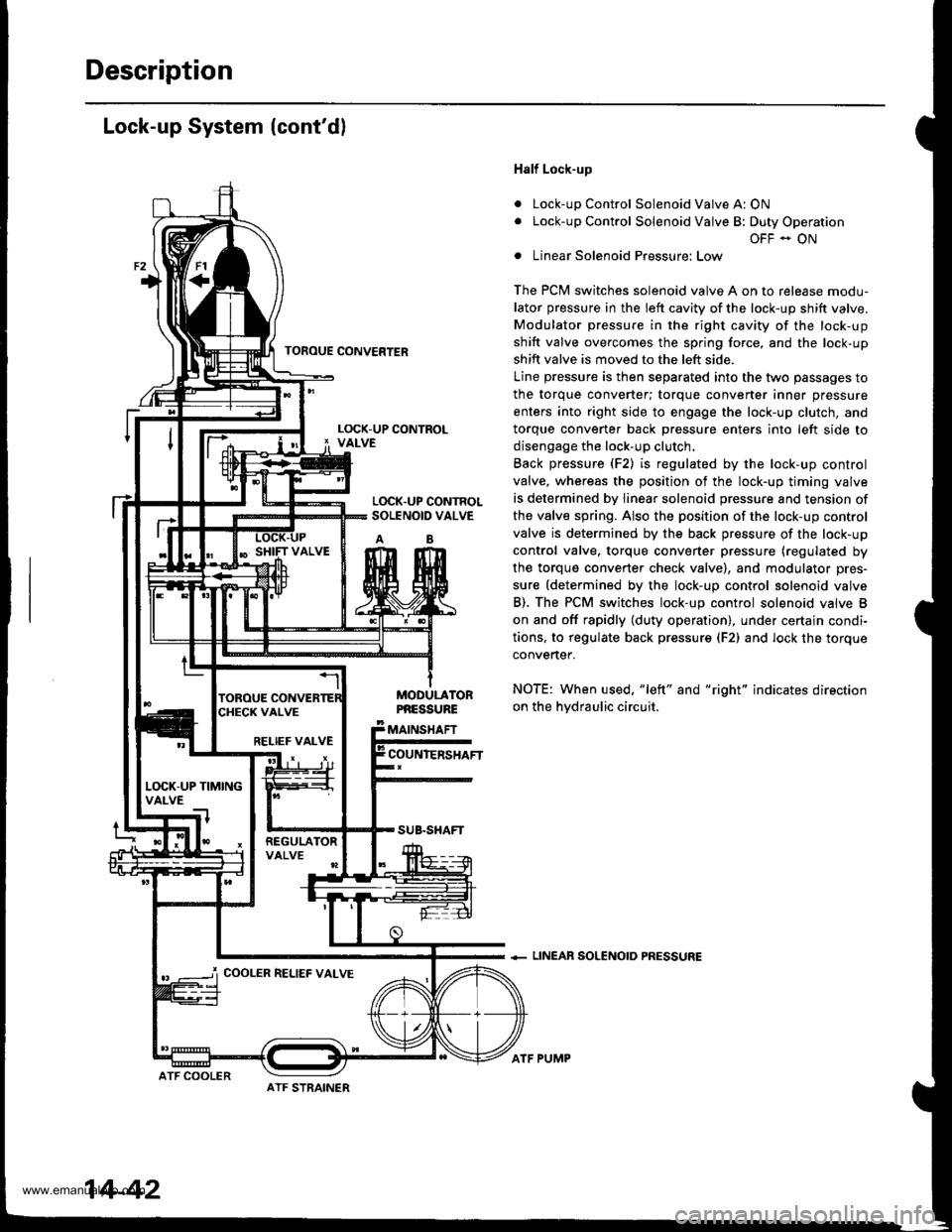
Half Lock-up
Lock-up Control Solenoid Valve A: ON
Lock-up Control Solenoid Valve B: Duty Operation
OFF - ON
Linear Solenoid Pressure: Low
The PCM switches solenoid valve A on to release modu-
lator pressure in the left cavity of the lock-up shift valve.
Modulator pressure in the right cavity of the lock-up
shift valve overcomes the spring force, and the lock-up
shift valve is moved to the left side.
Line pressure is then separated into the two passages to
the torque converter; torque converter inner pressure
enters into right side to engage the lock-up clutch, and
torque convener back Dressure enters into left side to
disengage the lock-up clutch.
Back pressure (F2) is regulated by the lock-up control
valve, whereas the position of the lock-up timing valve
is determined by linear solenoid pressure and tension of
the valve spring. Also the position of the lock-up control
valve is determined by the back pressure of the lock-up
control valve. torque converter pressure (regulated by
the torque converter check valve), and modulator pres-
sure (determined by the lock-up control solenoid valve
B). The PCM switches lock-up control solenoid valve B
on and off rapidly (duty operation), under certajn condi-
tions, to regulate back pressur€ (F2) and lock the torque
convertef.
NOTE: When used, "left" and "right" indicates direction
on the hvdraulic circuit.
+ LINEAR SOLENOID PRESSURE
TOFOUE CONVERTER
L(rcK.UP CONTROLSOLENOID VALVE
AB
MODULATORPNESSURE
MAINSHAFT
COUNIERSHAFTRELIEF VALVE
L(rcK-UP TIMINGVALVE
COOLER RELIEF VALVE
ATF STRAINER
14-42
ATF COOLER
ATF PUMP
www.emanualpro.com