Page 724 of 1395

Countershaft
Inspection (cont'd)
3.
4.
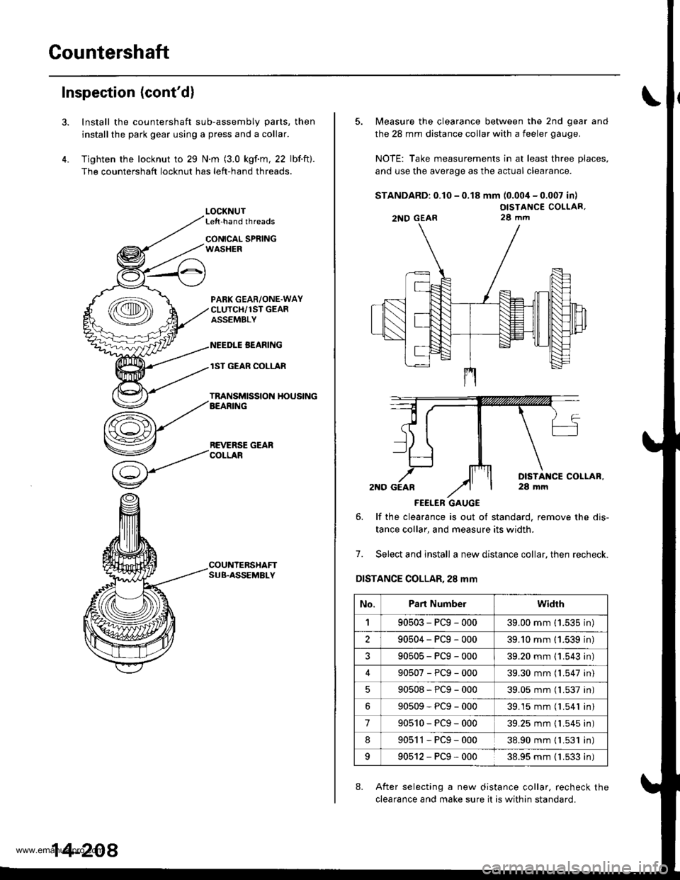
Install the countershaft sub-assembly parts, then
installthe park gear using a press and a collar.
Tighten the locknut to 29 N.m (3.0 kgf.m, 22 lbf.ft).
The countershaft locknut has left-hand threads.
LOCKNUTLe{t-hand threads
CONICAL SPRINGWASHER
PABK GEAR/ONE.WAYCLUTCH/1ST GEARASSEMBLY
NEEDLE BEANING
lST GEAR COLLAR
TRANSMISSION HOUSINGAEARING
REVERSE GEARCOLLAR
COUNTERSHAFTSUB.ASSEMBLY
14-208
5. Measure the clearance between the 2nd gear and
the 28 mm distance collar with a feeler gauge.
NOTE: Take measurements in at least three places,
and use the average as the actual clearance.
STANDARD: 0.10 - 0.18 mm (0.004 - 0.007 in)
OISTANCE COLLAR,28 mm
FEELER GAUGE
6. lf the clearance is out ot standard, remove the dis-
tance collar, and measure its width.
7. Select and install a new distance collar, then recheck.
DISTANCE COLLAR,28 mm
8. After selecting a new distance collar. recheck the
clearance and make sure it is within standard.
2NO GEAR
No.Part Numberwidrh
190503-PCg-00039.00 mm ('1.535 in)
290504-PCg-00039.'10 mm (1.539 in)
?90505-PCg-00039.20 mm {1.543 in)
90507-PCg-00039.30 mm (l.547 in)
90508*PCg-00039.05 mm (l.537 in)
90509-PCg-00039.15 mm (l.541 in)
790510-PCg-00039.25 mm {1.545 in)
890511-PCg-00038.90 mm { L531 in)
990512-PCg-00038.95 mm ( 1.533 in)
www.emanualpro.com
Page 1013 of 1395
Glass
Windshield Replacement (cont'dl
11. Glue the molding side seal and molding upper seal
to the molding on each side.
20-32
12. Align and glue the molding to the edge of the wind-
shield.
NOTE: Be careful not to touch the windshield
where adhesive will be applied.
a. With a brush, apply a light coat of primer (3lvl N-
200, or equivalent) to the edge ot the windshield
as shown,
b. Glue the adhesive tapes l3M 4212, or equivalent)
to both bottom edges of the windshield.
c. Align the alignment mark on the molding to the
alignment mark of the windshield.
d. Glue the molding to the edge of the windshield.
>: Alignment mark locations
ALIGNMENTApply primerMARK here. ln3ide , /
@
100 mm {3.9 in.l100 mm {3.9 in.}
ADHESIVE TAPEThic*ness: 1.2 mm (0.05 in.)Widthr 4 mm (0.16 in.)
r0 mm (1.6 in.l
www.emanualpro.com
Page 1018 of 1395
7. Glue the fastener to the inside face of quarter glass
as shown. lf the old quarter glass is to be reinstalled,
apply a light coat of primer (3M C- 100, or equivalent),
then apply butyltape to the quaner glass as shown.
NOTE:
. Be careful not to touch the quarter glass where
adhesive will be aDplied.
. Do not peel the separator off the butyl tape.
Width: 5.4 mm 10.25 in.)
BUTYL TAPE
I
w-mr
>t\
/\SS MOLDING
/'/.//// | Bttryl taee locations l3M 8628, or equivalent)Thickness:3.2 mm 10.13 in.l
>: Fastenoa location, I
FASTENER MOLDING
GLA
8. lnstall the fastener to the bodv as shown.
>: Fastener location, 1
1l mm(0.43 in.)
GLASS
400 mm (15.75 in.)
9. lf the old quarter glass is to be reinstalled, seal the
body hole with piece of urethane tape, Set the quar
ter glass upright in the opening and make alignment
marks across the quarter glass and body with a
grease pencil at the three points shown.
(cont'd)
20-37
ALIGNMENT MANK
10. Remove the quarter glass.
www.emanualpro.com
Page 1067 of 1395

Moldings
Door Moldings Replacement (cont'd)
It the old molding is to be reinstalled:
The following materials and tools are required to repair
the molding.
NOTE: Followthe manufacturer's instructions.
Materials: (Reference)
. Stripe remover
3M 08907
. Stripe adhesive remover
3M 08908
. Adhesive tape
3M Super Automotive Attachment Tape
Tools:
. Protective tape
. Knife or Cutter
. Sponge or Shop towel
. Infrared dryer
. Film
. Plastic putty knife
. Alcohol
CAUTION: Put on gloves to protect your hands,
1. lf necessary, replace any damaged clips on the mold-
ang.
2. Apply the stripe remover evenly to the bonding sur-
face of the body and molding.
3. Cover the bonding surface of the body and molding
with a film, then heat to 104 - 122"F (40 - 50'C) for 5- 10 minutes with an infrared dryer.
NOTE: Use care when heating to prevent deforma-
tion of the body and molding.
4. Carefully scrape the adhesive tape with a plastic
putty knife.
For removal of adhesive tape residue, follow-up with
stripe adhesive remover, then scrape the adhesive
tape with a plastic putty knife.
Remove the protective tape, then clean the bonding
surface with a sponge dampened in alcohol.
NOTE: Make sure the bonding surface is kept free or
water, oil and grease.
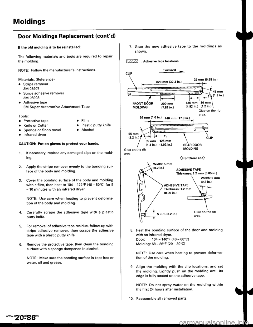
7. Glue the new adhesive tape
snown,
N : Adlesive tape locations
Forwerd L
820 mm 132.3 in.)
FRONTMOLDING
to the moldings as
25 mm {0.98 in.l
45 mm(1.8 in.l
200 mm(7.87 in.)
125 mm
{4.92 in.)30 mm
{1.2 in.}
t'.
Glue on the ribarea,26 mm (1.0 in.) 440 mm 117.3 in.l
35 mm 125 mm
{1.4 in.) {4.92 in.)REAR DOORMOLDING
(Front/rear end)
Width: 5 mm
Heat the bonding surface of the door and molding
with an infrared dryer.
Door: 104 - 140'F (40 - 60'C)
Molding: 68 - 86'F (20 - 30'C)
NOTE: Use care when heating to prevent deforma-
tion of the molding.
Align the molding with the clip locations, and set
the molding. Lightly push on the molding until its
edge is fully seated on the adhesive tape.
NOTE: Oo not spray water on the molding within
the first 24 hours after installation.
Reassemble all removed parts.10.
www.emanualpro.com