2000 HONDA CR-V srs
[x] Cancel search: srsPage 630 of 1395
Electrical Troubleshooting ('98 - 00 Modelsl
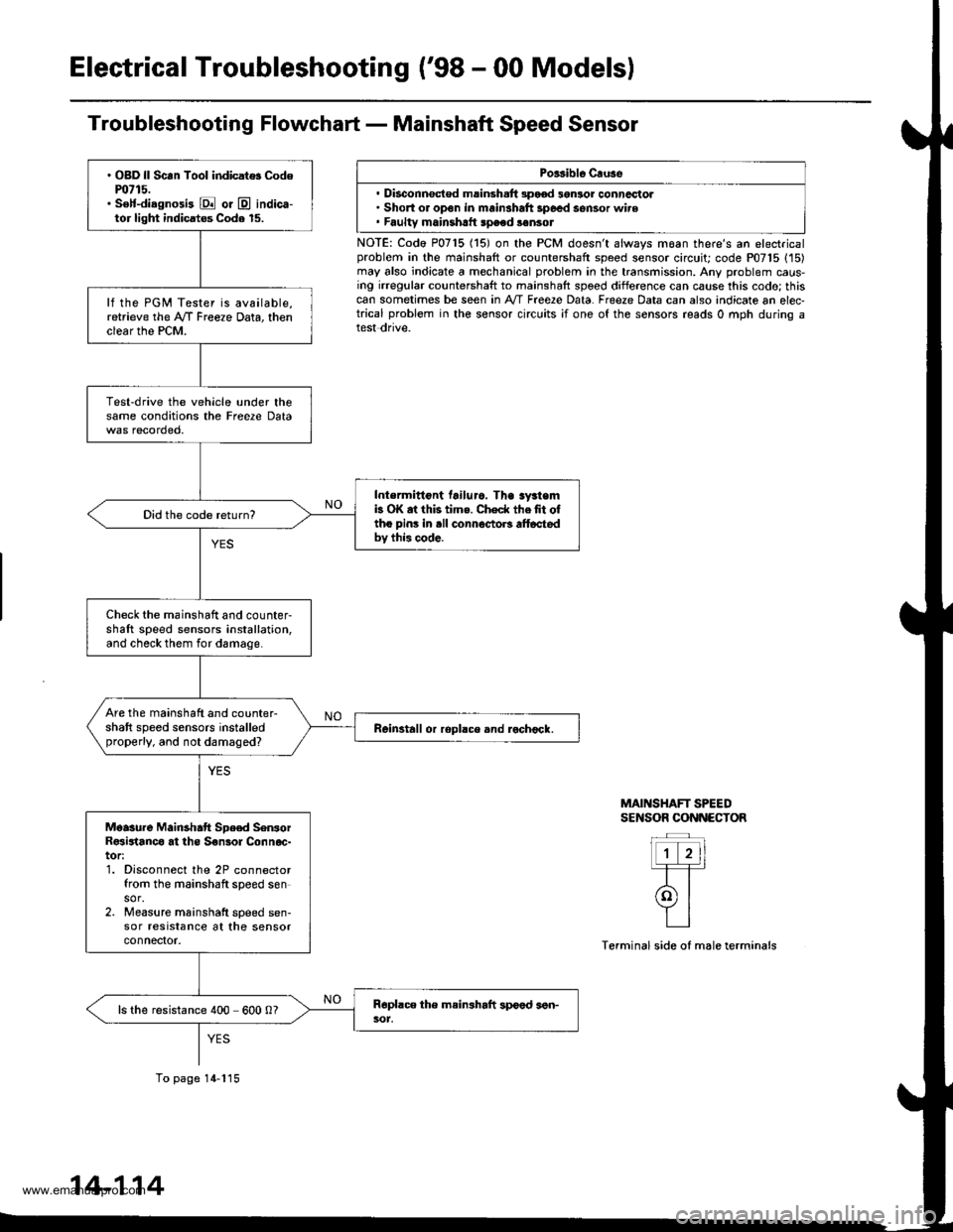
Troubleshooting Flowchart - Mainshaft Speed Sensor
Porsible Cruse
. Disconnsct€d msinsh.ft 3pood 3gnlor conncctol. Short or open in mainshaft 3poed sensor wire. Faultv mainshrtt speed sonsot
NOTE: Codo P0715 (15) on the PCM doesn't always moan there's an electricalproblem in the mainshaft or countershaft speed sensor circuit; code P07'15 (15)may also indicate a mechanical problem in the transmission. Any problem caus-ing irregular countershaft to mainshaft spoed difference can cause this codo; thiscan sometimes be seen in A'/T Free2e Data. Freeze Data can also indicate an elec-trical problem in the sensor circuits ;f one of the sensors reads 0 mph during atest dnve.
MAINSHAFT SPEEDSENSOR CONNECTOR
Terminal side of male terminals
. OBD ll Scan Tool indicat$ Codem715.. S€lf-diagnosi3 E or @ indica-tor light indicatos Code 15.
lf the PGM Tester is available,retrieve the A/f Freeze Data, thenclear the PCM.
Test-drive the vehicle under thesame conditions the Freere Data
Intermittont tailuro. Tha sy3temb OK at this tims. Check thefit oftho pins in .ll connoctoB alt6ctedbv this code.
Did the code return?
Check the mainshaft and counter-shaft speed sensors installation,and check them for damage.
Are the mainshaft and counter-shaft speed sensors installedproperly, and not damaged?Reinstall or ropllce and rochock.
Moasure Mainshatt Spe€d SenrorR€sirtanco at ths S€nsol Connoc-tor:1. Disconnect the 2P connectorfrom the mainshaft speed sensor.2. Measure mainshatt speed sen-sor resrstance at the sensorconnefior.
ls the resistance 400 600 0?
To page 14-115
14-114
www.emanualpro.com
Page 660 of 1395
Interlock System
Interlock Control Unit Input Test
SRS components are located in this area. Review the SRS component locations, precautions, and procedures in the SRS
section (24) before performing repairs or service.
'1. Remove the instrument panel lower cover (see section 20).
2. Disconnect the 8P connector from the interlock control unit.
3. Inspect the connector and connector terminals to be sure they are all making good contact.
. lf the terminals are bent, loose, or corroded, repair them as necessary, and recheck the system
. lf the terminals look OK, make the following input tests at the connector.
- lf a test indicates a problem, find and correct the cause, then recheck the system
- lf all the input tests prove OK, substitute a known-good control unit, and recheck the system. lf the check is OK,
the control unit must be faulty; replace it.
NOTE: lf the shift lock solenoid clicks when the ign ition switch is tu rned ON (ll) while pressing the brake pedal withthe
shift lever in E position, the shift lock system is OK. lf the shift lever cannot be shifted from E position. test the A/T
gear position switch.
14-144
www.emanualpro.com
Page 662 of 1395
lnterlock System
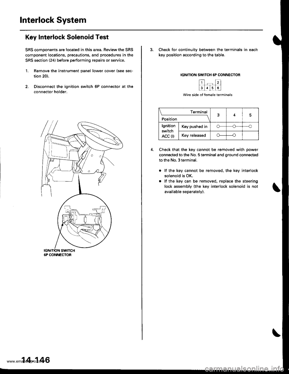
Key Interlock Solenoid Test
SRS comoonents are located in this area. Review the SRS
component locations, precautions. and procedures in the
SRS section (24) before pertorming repairs or service.
1. Remove the instrument panel lower cover (see sec-
tion 20).
2. Disconnect the ignition switch 6P connector at the
connector holder.
6P CONNECTOR
14-146
3. Check for continuitv between the terminals in each
key position according to the table.
IGNITION SWITCH 6P CONNECTOR
Check that the key cannot be removed with power
connected to the No. 5 terminal and ground connected
to the No. 3 terminal.
lf the key cannot be removed. the key interiock
solenoid is OK.
lf the key can be removed, replace the steering
lock assembly (the key interlock solenoid is not
available separately).
\____________r{r4
Position
lgnition
switch
ACC 0)
Key pushed ino---'o
Key releasedo----o
www.emanualpro.com
Page 663 of 1395
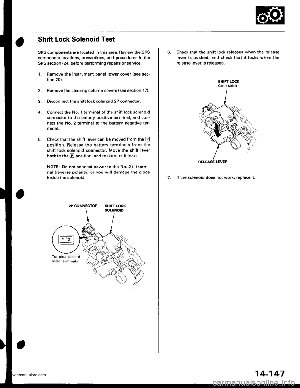
Shift Lock Solenoid Test
SRS components are located in this area. Review the SRS
component locations, precautions, and procedures in the
SRS section (24) before performing repairs or service,
'1. Remove the instrument panel lower cover (see sec-
tion 20).
2. Remove the steering column covers (see section 17).
3. Disconnect the shift lock solenoid 2P connector.
Connect the No. 1 terminal of the shift lock solenoid
connector to the battery positive tgrminal, and con-
nect the No. 2 terminal to the battery nogative ter-
mrnal.
Check that the shift lever can be moved from the E
oosition. Release the batterv terminals from the
shift lock solenoid connector. Move the shift lever
back to the E position, and make sure it locks.
NOTE: Do not connect power to the No. 2 (-) termi-
nal {reverse polarity) or you will damage the diode
inside the solenoid.
2P CONNECTOR SHIFT LOCK
6. Check that the shift lock releases when the release
lever is pushed, and check that it locks when the
release lever is released,
7. lf the solenoid does not work, replace it.
14-147
www.emanualpro.com
Page 664 of 1395
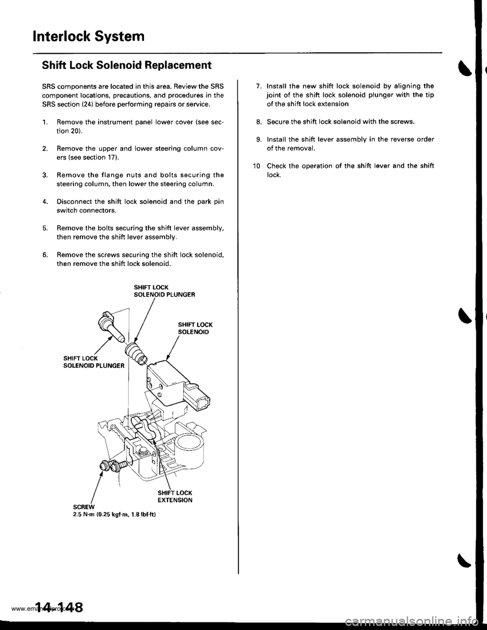
Interlock System
Shift Lock Solenoid Replacement
SRS components are located in this area. Review the SRS
component locations, precautions, and procedures in the
SRS section (24) before performing repairs or service.
'L Remove the instrument panel lower cover (see sec-
tion 20).
2. Remove the upper and lower steering column cov-
ers (see section 17).
3. Bemove the flange nuts and bolts securing the
steering column, then lower the steering column.
4. Disconnect the shift lock solenoid and the park pin
switch connectors.
Remove the bolts securing the shift lever assembly,
then remove the shift lever assemblv.
Remove the screws securing the shift lock solenoid,
then remove the shift lock solenoid.
2.5 N.m {0.25 kgl.m, 1.8lbf.ft}
14-148
7.Install the new shift lock solenoid by aligning the
joint of the shift lock solenoid plunger with the tip
of the shift lock extension
Secure the shift lock solenoid with the screws,
Install the shift lever assembly in the reverse order
of the removal.
Check the operation of the shift lever and the shift
lock.
9.
10
www.emanualpro.com
Page 665 of 1395

Park Pin Switch Test
SRS components are located in this area. Review the SRS
compongnt locations, precautions, and procedures in the
SRS section (24) before performing repairs or service,
1. Remove tho instrument panel lower cover (see sec-
tion 20).
Remove the upper and lower steering column cov-
ers (see section 17).
Disconnect the park pin switch connector.
Shift the shift lever into E position, then check for
continuity betwsgn these conngctor terminals:
. '97 - 98 models; No. 1 and No, 3 terminals of the
park pin switch connector.
.'99-00 models: No. 3and No. 4terminalsof the
park pin switch/Over-Drive {O/D) switch connec-
tor.
There should be continuity,
37 - 98 MODELS:
'99 - 00 MODELS:
PARK PIN SWITCH/oVER-DRTVE {O/D) SWTTCHCONNECTOR
PAR( PIN
.qI
Shift the shift lever out of the E position, and check
for continuity between the terminals as in step 4.
Thsre should be no continuity.
lf the park pin switch is faulty, replace it.
14-149
www.emanualpro.com
Page 666 of 1395

Interlock System
Park Pin Switch Replacement -'97 - 98 Models
SRS components are located in this area. Review the SRS component locations, precautions, and procedures in the SRS
section (24) before performing repairs or service.
1. Remove the instrument Danel lower cover (see section 20).
2. Remove the upper and lower steering column covers (see section li,.
3. Remove the flange nuts and bolts securing the steering column. then lower the steering column.4. Disconnect the shift lock solenoid and the park pin switch connectors.
5. Remove the harness clamp bracket.
6. Remove the bolts secu ring the shift lever assembly, then removetheshift lever assembly.
7. Remove the screws securing the shift lock solenoid. then remove the shift lock solenoid,
8. Remove the parkpin switch connector from the shift lever control bracket.
9. Remove the control checker from the shift lever control bracket.
10. Remove the park Din switch from the control checker.
PARK PIN SWITCH
PARK PINSWITCH CONNECTOR
scnEw2.5 N m 10.25 kgt.m, 1.8 lbtftl
9.3 N.m 10.95 kgf.m, 6.9 lbl.ft)
BRACKETCONTROL CHECKER
11. Install the new Dark Din switch on the control checker.
12. lnstall the control checker on the shift lever control bracket.
13. Routethe park pin switch harness through thecutoutofthe shift lever control bracket, then install the park pin switchconnector on the bracket.
14. Install the sh ift lock solenoid by a ligning the joint of the sh ift lock solenoid plu nger with the tip of the shift lock exten-sion.
15. Secure the shift lock solenoid with the screws.
15. Install the shift lever assembly in the reverse order of the removal.'17. Check the operation of the shift lever and the shift lock.
14-150
www.emanualpro.com
Page 667 of 1395

Park Pin Switch - Over-Drive (O/Dl Switch Replacement -'99 - 00 Models
SRS components are located in this area. Review the SRS component locations, precautions, and procedures in the SRS
section {24) before performing repairs or service.
NOTE: lf replacement of the park pin switch or the O/D switch is required. replace them as a set.
1. Remove the instrument panel lowercover(see section 20).
2. Remove the upper and lower steering column covers (see section 17).
3. Remove the flange nuts securing the steering column. then lower the steering column.
4. Disconnect the shift lock solenoid and the park pin switch - O/D switch connectors
5. Remove the harness clamp bracket.
6. Remove the bolts securing the shift lever assembly, then remove the shift lever assembly.
7. Remove the screws securing the shift lock solenoid, then remove the shift lock solenoid.
8. Cut the O/D switch wires (REDand BLK),then remove the con nector from the shift lever control bracket
9. Remove the control checker from theshift lever control bracket
10. Remove the oark oin switch from the control checker.
11. Remove the shift lever knob from the shift lever, then remove the O/D switch from the shift lever knob.
SCREW2.5 N.m 10.25 kgtm, 1.8lbf,ft)SHIFT LEVER CONTROLBRACKET
PARK PIN SWITCH -
o/D swlTcHCONNECTOR
2.5 N.m (0.25 kgt m,1.8 tbf.fr)
HABNESS CLAMP BRACKET
9.3 N.m 10.95 kgl.m.6.9 tbf ft)
SHIFT LEVER KNOB6-12N,m{0.6 - 1.2 kgt.m.4 - 8.7 lbf ftl
SHIFT LEVERo/o swlTcH
12. Route the new O/D switch wires through the shift lever knob, shift lever, and shift lever control bracket, then install
the knob on the shift lever, and install the switch in the knob.
13. Install the new park pin switch on the control checker, then install the control checker on the shift lever control brack-
et.
14. Routethe parkpin switch harnessthroughthecutoutoftheshift lever control bracket.
15. Install the O/D switch wire terminals in the connector cavities securely. The wire terminals can be installed in cavity
No. 1 or No.2.
16, Install the connector and the harness clamp on the bracket.
17. tnstall the shift lock solenoid by aligning the joint ot the shift lock solenoid plu nger with the tip of the shift lock exten-
sion, then secure the shift lock solenoid with the screws,
18. lnstall the shift lever assemblv inthe reverse order of removal.
19. Adjust the clearance between the O/D switch wires and the edge of the sh ift lever control bracket (see page 14-270).
20. Check the shift lever operation and shift lock operation.
14-151
www.emanualpro.com