Page 358 of 1395

ldle Gontrol System
Air Conditioning Signal (cont'dl
(From page 11-'155)
JUMPERWIRE
UNOER.HOOD FUSE/RELAYBOX 9P CONNECTOR tqt52)
123I
56I
ACC IBLK/RWire side ofACC IBLK/REDIWire side of femaletermrnats
A t32PlPCM CONNECTORS C t3rp)
Wire side ol lemale terminals
Ch6ck for an open in th€ wire(ACC linel:Momentarily connect the under-hood fuse/relay box 9P connectorterminal No.5 to body groundwith a jumper wire several times.
ls there a cl;cking noise fromthe 4!/C compressor clutch?
ls there a clicking noise fromthe 4!/C compressor clutch?See air condiiioner inspection{see section 221.
Repai. op6n in the wire betwoenthe PcM (A17) and tho A/Cclutch relay.
Check the A/C operation:1. Start the engine.2. Turn the blower switch ON.3. Turn the A"/C switch ON.
Check for an open in the wire(ACS line):Measure voltage between PCMconnector terminals Ag and C5.
Does the A,/C operate?
Air conditioning signal is OK.
Repair open in the wire betweenthe PCM lCSl and the A/C awitch.ls there less than 1.0 V?
- Subqtitute a known-good FCM.nd r€ch6ck. lt 3ymptom/indi-cation goes awav, replece theoriginal rcM.- Soe th€ eir conditioner in3pec-tion (s6€ aec.tion 22).
www.emanualpro.com
Page 361 of 1395

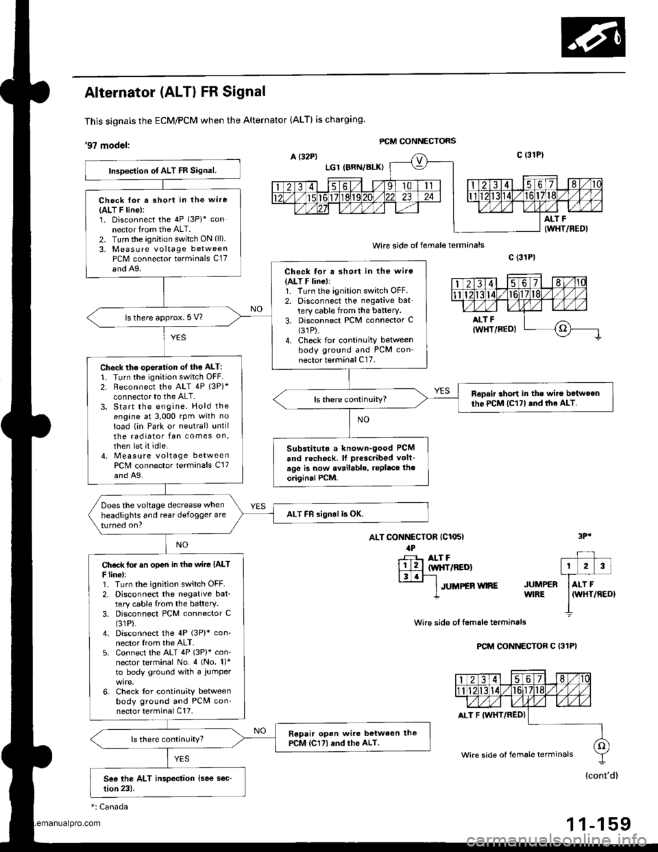
Alternator (ALT) FR Signal
This signals the ECM/PCM when the Alternator (ALTI is charging.
,97 modet: PCM GONNECTORS
wire side of female terminals
ALT CONNECTOR (C1O5I
lPr-F- ALT F
lll2llw|{frREDl|3.r-'l-
lruueen wne
c (31P|
wire side ol f€male terminals
PCM CONNECTOR C I31P)
3Pr
JUMPERWIRE
Inspection ot ALT FR Signal.
Check lor a short in the wire
{ALT F line}:1. Disconnect the 4P 13Pi* connector from the ALT.2. Turn the ignition switch ON (ll)
3, Measure voltage betweenPCM connector terminals C17
and A9.Check for a short in the wire(ALT F linel:1. Turn the ignition switch OFF.2. Disconnect the negative bat'tery cable from the battery.3. Disconnect PCM connector C(31P).
4. Check for continuity betweenbody ground and PCM connector terminal C17.
ls there approx. 5 V?
Check th€ ope.ation of the ALT:
1. Turn the ignition switch OFF2. Reconnect the ALT 4P {3Pi*connector to the ALT.3. Start the engine. Hold theengine at 3,000 rpm with no
load (in Park or neutral) untilthe radiator fan comes on,
then let it idle.4. Measure voltage betweenPCM connector terminals C17and A9.
Ropeir short in the wir6 betweonthe PCM lC17l and the ALT.
Substitut. a known-good PCM
and recheck. lf prescribed volt-
age is now availablo, replace the
originalPCM.
Does the voltage decrease when
headlights and rear defogger are
turned on?ALT FR signal b OK.
Ch€d( for an op€n in tho wire IALTF linel:1. Turn the ignition switch OFF.2. Disconnect the negative bat-tery cable lrom the battery.3. Disconnect PCM connector C(31P).
4. Disconnect the 4P (3P)* con-nector lrom the ALT.5. Connect the ALT 4P (3P)* con-nector terminal No. 4 (No. 1)*to body ground with a iumper
6. Check for continuity betweenbody ground and PCN4 con'nector terminal Cl7.
Repair open wi.e between thePCM lCl7l and the ALT.ls there continuity?
ALT F IWHT/REDI
Wire side of female terminals
1 1-159
www.emanualpro.com
Page 362 of 1395
![HONDA CR-V 2000 RD1-RD3 / 1.G Workshop Manual
ldle Gontrol System
Alternator (ALT) FR Signal (contdl
98 - 00 modols:
ALT CONNECTOR (C1I}5I
4P
rH] Arr FllltwHr/REo)l3laF1
I JUMPER WIRE JUMPER+ WIRE
ECM/PCM CONNECTORS
Wire side of female termi HONDA CR-V 2000 RD1-RD3 / 1.G Workshop Manual
ldle Gontrol System
Alternator (ALT) FR Signal (contdl
98 - 00 modols:
ALT CONNECTOR (C1I}5I
4P
rH] Arr FllltwHr/REo)l3laF1
I JUMPER WIRE JUMPER+ WIRE
ECM/PCM CONNECTORS
Wire side of female termi](/manual-img/13/5778/w960_5778-361.png)
ldle Gontrol System
Alternator (ALT) FR Signal (cont'dl
'98 - 00 modols:
ALT CONNECTOR (C1I}5I
4P
rH] Arr Fl'l'ltwHr/REo)l3laF1
I JUMPER WIRE JUMPER+ WIRE
ECM/PCM CONNECTORS
Wire side of female terminals
ECM/PCM CONNECTOR C {31PI
Wire side of female terminals
Wire side of female terminals
ECM/PCM CONNECTOR C {31P}
": Canada
1 1-160
B (25P)
Insp€ction of ALT FR Signsl.
Check fo. a shon in th. wire {ALTF linel:1. Disconn6ct the 4P (3P)* con-nector from the ALT.2. Turn the ignition switch ON {ll).3. Measure voltage between ECM/PCM connector terminals C5and 820.Ch€ck for a sho.t in iho wirc lAlTF lino):1. Turn the ignition switch OFF.2. Disconnecl the negative bat,tery cable from the battery.3. Disconnect ECM,PCM connec-torC (31P).
4. Check for continuity betwoenbody ground and ECM/PCMconnector terminal c5.
ls there approx. 5 V7
Check the opcration of the ALT:1. Turn the ignitioo switch OFF.2. Reconnect rhe ALT 4P (3P)*connector to the ALT.3. Start the engine. Hold theengine at 3,000 rpm with noload (in Park or neutral) untilthe radiator lan comes on,then let it idle.4. Measure voltage between ECM/PCM connector terminals C5and 820.
Roprir lhort in tho wirc bstweentho ECM/PCM {Csl and the ALT.
Substitut. r known-good ECM/PCM and roch.ck. It Droscrib.dvoltage b now lvrilabls, .eplaccth. o.igin!l ECM/PCM.
Does the voltage decrease whenheadlights and rear defogger areturned on?ALT FR 3ignol is OK,
Chock lor an opon in tha wire (ALTF linel:1. Turn the ignition switch OFF.2. Disconnect the negative bat-tery cable from the battery.3. Disconnect ECM/PCM con-nector C (31P).4. Disconnect the 4P 13P)* con,nector from the ALT.5. Connect the ALT 4P {3P)* con-nector terminal No. 4 1No. 1)*to body ground with a jumper
6. Check for continuity betwe€nbody ground and ECM/PCMconnector terminal C5.
Rsprir opan wiro batw.en thoECM/PCM lcsl .nd th. ALT.ls there continuity?
AI.T F IWHT/REDI
ALT F {WHT/REDI
Wire side ot Iemale terminals
www.emanualpro.com
Page 386 of 1395

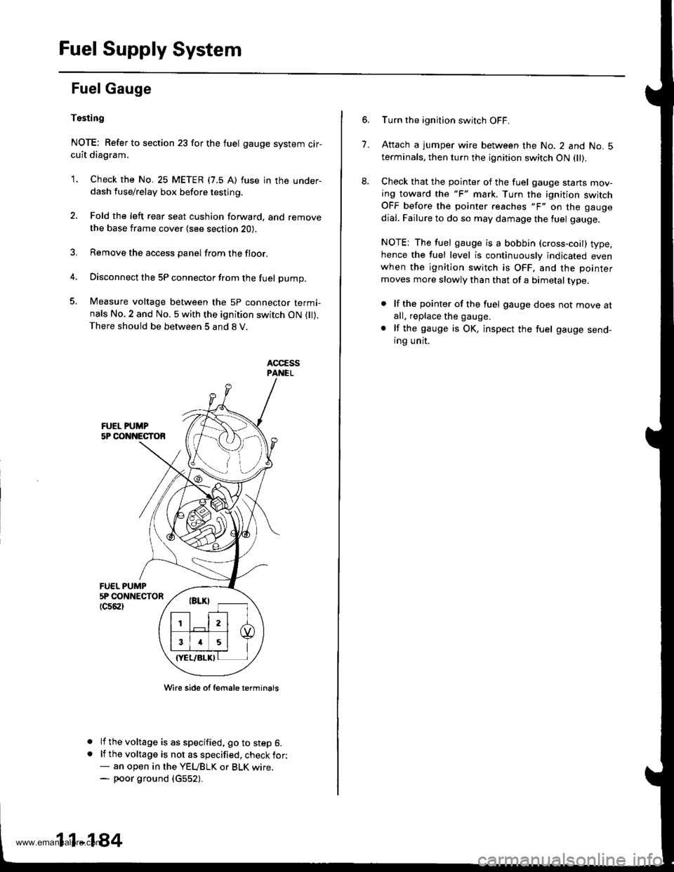
Fuel Supply System
Fuel Gauge
Tssting
NOTE: Refer to section 23 for the fuel gauge system cir-cuit diagram.
'1. Check the No. 25 METER (7.5 A) fuse in the under-dash fuse/relay box before testing.
2. Fold the left rear seat cushion forward, and remove
the base frame cover {see section 20).
3. Remove the access panel from the floor.
4. Disconnect the 5P connector from the fuel pump.
5. Measure voltage between the 5P connector termi-nals No.2 and No. 5 with the ignition switch ON ( ).There should be between 5 and 8 V.
FUEL PUMP5P CONNECTOR
tc56al
a
a
Wire side of female t€rminals
lf the voltage is as specified, go to step 6.lf the voltage is not as specified, check for:- an open in the YEUBLK or BLK wrre.- poor ground (c552).
11-184
7.
Turn the ignition switch OFF.
Attach a jumper wire between the No. 2 and No. 5terminals, then turn the ignition switch ON fll).
Check that the pointer of the fuel gauge starts mov-ing toward the "F" mark. Turn the ignition switchOFF before the pointer reaches "F" on the gauge
dial. Failure to do so may damage the luel gauge.
NOTE: The fuel gauge is a bobbin (cross-coil) type,hence the fuel level is continuously indicated evenwhen the ignition switch is OFF, and the pointer
moves more slowly than that of a bimetal type.
. lf the pointer of the fuel gauge does not move atall. replace the gauge.
. lf the gauge is OK, inspect the fuel gauge send-ing unit.
www.emanualpro.com