2000 HONDA CR-V intake system
[x] Cancel search: intake systemPage 277 of 1395
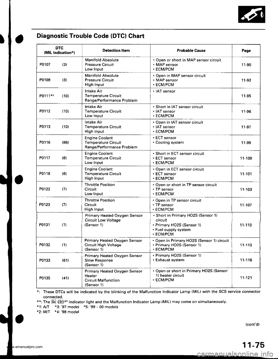
Diagnostic Trouble Code (DTCI Chart
*: These DTCS will be indicated by the blinking of the Malfunction Indicator Lamp (MlL) with the SCS service connector
connected.**: The E (E)*u indicator tight and the Malfunction Indicator Lamp (MlL) may come on simultaneously.*1' AIT *3 '97 model +5; '99 - 00 models*2: MlT *4:'98 model
{cont'd)
11-75
DTC(MlL indication*lDetection ltemProbable CausePago
P0107 (3)Manifold Absolute
Pressu.e CircuitLow Input
Open or short in MAP sensor circuit
MAP sensor
ECMiPCM
't 'l-90
P0108 {3)
Manifold AbsolutePressure Circuit
High Input
Open in MAP sensor circuitMAP sensor
ECM/PCM
11-92
P01 1 1*3 (10)Intake Air
Temperature Circuit
Range/Performance Problem
. IAT sensor
11-95
P0112 (10)lntake Air
Temperature CircuitLow Input
Short in IAT sensor circuit
IAT sensorECM/PCM1 1-96
P0113 (10)lntake Air
Temperature Circuit
High lnput
Open in IAT sensor circuit
IAT sensor
ECM/PCM
'I 1-97
P0116 (86)Engine CoolantTemperature CircuitRange/Performance Problem
ECT sensor
Cooling system1 1-99
P0117 (6)Engine Coolant
Temperature Circuit
Low Input
Short in ECT sensor circuit
ECT sensor
ECM/PCM
1 1-100
P0118 (6)Engine Coolant
Temperature CircuitHigh Input
Open in ECT sensor circujt
ECT sensor
ECM/PCM
11-101
P0122 \11
Throttle Position
Circuit
Low Input
Open or short in TP sensor circuitTP sensor
ECM/PCM
11-103
P0123 l7l
Throftle Position
Circuit
High Input
Open in TP sensor circuit
TP sensor
ECM/PCM11-107
P0131 (1)
Primary Heated Oxygen Sensor
Circuit Low Voltage(Sensor 1)
Short in Primary HO2S {Sensor 1)
circuit
Primary HO2S (Sensor 1)
Fuel supply system
ECM/PCM
1 1-1 10
P0132 (1)Primary Heated Orygen SensorCircuit High Voltage(Sensor 1)
Open in Primary HO2S (Sensor 1) circuitPrimary HO25 (Sensor 1)ECM/PCM
'11113
P0133 (61)Primary Heated Oxygen Sensor
Slow Response(Sensor 1)
. Primary HO2S (Sensor 1). Exhaust system11'I 16
P0135 (41)
Primary Heated Oxygen SensorHeater
Circuit Malfunction
{Sensor 1)
. Open or short in Primary HO2S (Sensor'l) heater circuit. ECM/PCM11-12'l
www.emanualpro.com
Page 298 of 1395
PGM-FI System
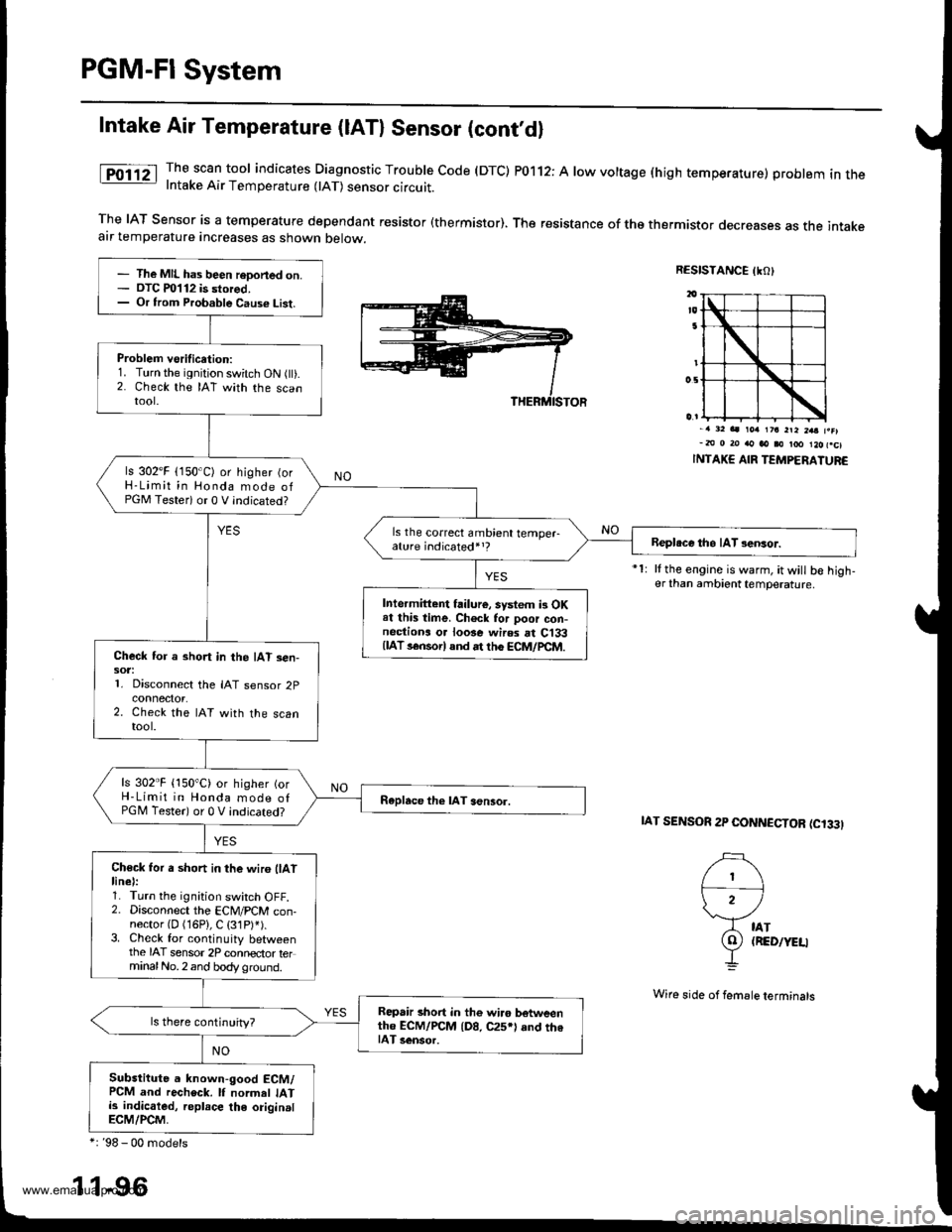
Intake Air Temperature (lAT) Sensor (cont'dl
The scan tool indicates Diagnostic Trouble code (DTC) P0112: A low voltage (high temperature) problem in theIntake Air Temperature 0AT) sensor circuit.
The IAT Sensor is a temperature dependant resistor (thermistor). The resistance of tho thermistor decreases as the intakeair temperature increases as shown below.
RESISTANCE IKO)
i')
)2 /
A tAr
9) (RED/YEU
-L
-. 32 aa rorr 1?a 2ra 2aa f.el-m 0 20 rto ao i0 too l2ofcl
INTAKE AIR TEMPERATUR€
It the engine is warm, it will b€ high-er than ambient temperature.
IAT SENSOR 2P CONNCCTOR (C'33I
- The MIL has been reDoned on.- OTC m112 is stored,- Or from Probable Caus€ List.
Problem vsrification:1. Turn the ignition switch ON flt).2. Check the IAT with the scantool.
ls 302'F (150'C) or higher (orH-Limit in Honda mode ofPGM Testeri or 0 V indicated?
ls the correct ambient temper-ature indicated,,?Beploce tho IAT sensor.
Intermittent failure, system i3 OKat this time. Ch6ck for poor con-nectiona o. loose wires rt C133{lAT s€nsorl and rt th6 ECM/pCtr4.Check for a short in the IAT sen-sot:1. Disconnect the IAT sensor 2p
2. Check the IAT with the scantool.
ls 302"F {150"C) or higher {orH-Limit in Honda mode ofPGM Tester) or 0 V indicated?Raplace the lAT aensor.
Ch€ck for a short in the wir6 llAtlinel:1. Turn the ignition switch OFF.2. Disconnect the ECM/PCM con-nector {D (16P}, C (31P)').3. Check for continuity betweenthe IAT sensor 2P connector terminalNo.2 and body ground.
Repair short in the wi.o botweenth6 ECM/rcM {D8, C25*l and th6IAT 3ensor.
Substitute a known-good ECM/PCM and recheck. lf normel IATis indicaled, replace the originalECM/PCM,
*: '98 - 00 models
1 1-96
Wi16 side of femsle terminals
www.emanualpro.com
Page 300 of 1395
PGM-FI System
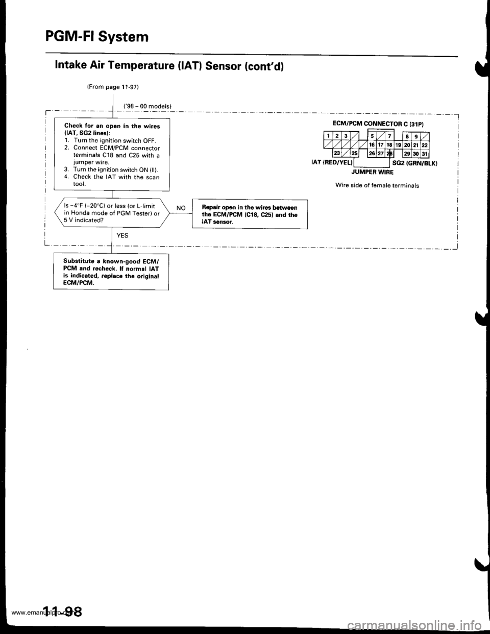
Check for an open in the wires{lAT, SG2lines):1. Turn the ignition switch OFF.2. Connect ECM/PCM connectorterminals C18 and C25 with ajumper wire.3. Turn the ignition switch ON (ll).4. Check the IAT with the scantool.
ls -4'F 1-20"C) or less (or L limitin Honda mode of PGM Testeri or5 V indicated?
Repsir op€n in the wirca batweenthe ECM/PCM 1C18, C25l and theIAT s€nsor.
Substitute a known-good ECM/PCM rnd recheck, lf normal IATis indicated, leplaco the originslECM/PCM.
Intake Air Temperature (lATl Sensor (cont'd)
(From page 11,97)
'l
ECM/PCM CINNECTOR C t3lPl
257II
./ 16171819 202122234 Wp,29c)31
sG2IAT {RED/YELI{GRN/BLK)
JUMPER WIRE
Wire side of fernale terminals
I
1 1-98
www.emanualpro.com
Page 351 of 1395
ldle Control System
System Description
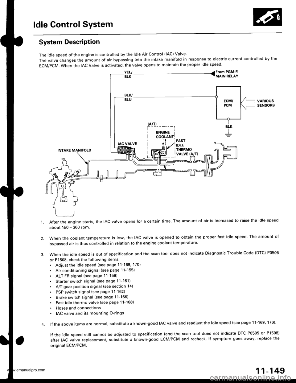
The idle speed of the engjne is controlled by the ldle Air Control (lAC) Valve'
The valve changes the amount of air bypassing into the intake manifold in response to electric current controlled by the
ECM/PCM. When the lAc valve is activated, the valve opens to maintain the proper idle speed.
YEL/ From PGM'FI
BLK TMAIN RELAY
VARIOUSSENSORS
4.
IAC VALVE
INTAKE MANIFOLD
After the engine starts, the IAC valve opens for a certain time. The amount of air is increased to raise the idle speed
about 150 - 300 rpm.
when the cootant temperature ts row, the lAc valve is opened to obtain the proper fast idle speed The amount o{
bvoassed air is thus controlled in relation to the engine coolant temperature
When the idle speed is out o{ specification and the scan tool does not indicate Diagnostic Trouble Code (DTC) P0505
or P1508, check the following items:
. Adjust the idle speed (see page 11-169, 170)
. Air conditioning signal (seepagell-1551
. ALT FR signal (see page 1l-159)
. Starter switch signal (see page 11-16'1)
. A,/T gear position signal (see section 14)
. PSP switch signal (seepagell-162)
. Brake switch signal (see page 11-165)
. Fast idlethermovalve (see page'11 168)
. Hoses and connecttons. IAC valve and its mounting O-rings
lf the above items are normat, suDslitute a known-good IAC valve and readjust the idle speed {see page 11-169, 170)
lf the idle speed still cannot be adjusted to specification (and the scan tool does not indicate DTC P0505 or Pl508)
after IAC valve reolacement, substitute a known-good ECM/PCM and recheck lf symptom goes away' replace the
original ECM/PCM.
11-149
www.emanualpro.com
Page 352 of 1395

ldle Control System
ldle Control System
I P0505 | The scan tool indicates Diagnostic T.ouble Code (DTCI PO5O5: ldlecontrol svstem mattunction.
NOTE: lf DTC P1508 is stored at the same time as DTC P0505, troubleshoot DTC P1508 first. then troubleshoot DTC p0505.
Possibls Cause
. IAC valve mechanical malfunction. Throttle body clogged port, improper adlustment. Intake manifold gasket leakaging. Intake air hose loose leakaging. Vacuum hose leakaging
a ECT sensor incorrect output. Throttle Position sensor incorrect output
Troubleshooting Flowchart
The MIL has been reDorted on.DTC P0505 is sto.ed.
Problem verificationi1. Start the engine. Hold theengine at 3,000 rpm with noload (in Park or neutral) untilthe radiator Ian comes on, thenlet it idle.2. With the scan tool, check thelollowing items.- Throttle position should beapprox. 10% with the throt-tle {ully closed.- Engine coolant temperature shorJld be 194 - 205'F(90 - 96"C).lf they are not within thespec., repair the faulty sen-sor circuit.3 Check the engine speed atidle with no-load conditions:headlights, blower fan. reardefogger, radiator lan, and airconditioner are not operaling,
Inte.mittent failure. syltem is OKat this time.ls it 750 {730)* i 50 rpm?
ls il 700 (680)' rpm or less?
{To page 11-151)(To page 1'l-151)
l:'99 - 00 models
www.emanualpro.com
Page 354 of 1395

ldle Control System
ldle Air Control llAC) Valve
The scan tool indicates Diagnostic Trouble Code (DTC) Pl508: A probtem in the ldle Air Controt flAC) varvecircuit.
The IAC Valve changes the amount of air bypassing the throttle body in response to a current signal from the ECM/PCM inorder to maintain the proper idle speed.
37 model;
IAC VALVE 2P CONNECTOR {C132}
,f rcp'# IYEL/BI.(II2f-1-d)
Y
Wir€ side of female terminals
PCM CONNECTOR A I32PI
tacvIBLK/BLU)
From AIR To INTAKECLEANER MANIFOLD
Wire side of female terminals
The MIL has beon .eport€d on.OIC Pl508 is sto.ed.
Problem veiification:1. Do the PCM Reset Procedure.2. Start the engine, and warm itup to normal operating tem-perature.
Inte.mittent failure, systcm b OKat thi3 time. Check tor poo. con-nections or loose wircs at C132(lAC v.lvel and at the PCM.
ls DTC Pl508 indicated?
Check lor an open in the wir6{lGPl lins}:1. Turn the ignition switch OFF.2. Disconnect the IAC valve 2Pconnector.3. Turn the ignition switch ON {ll).4. Measure voltage between bodyground and the IAC valve 2Pconnector term inal No.2.
Repair open in the wire trctwoontha IAC v!lv6 and the PGM-Flmain relly.
Chock for an opan o. short in thowi.e (lACv linel:1. Turn the ignition switch OFFand reconnect the IAC valve2P connector.2. Disconnect the PCM conneclorA (32P).
3. Turn the ignition switch ON {ll).4, Measure voltage betweenbody ground and PCM con-nector terminal A12.
{To page 1l-153)
www.emanualpro.com
Page 370 of 1395
ldle Control System
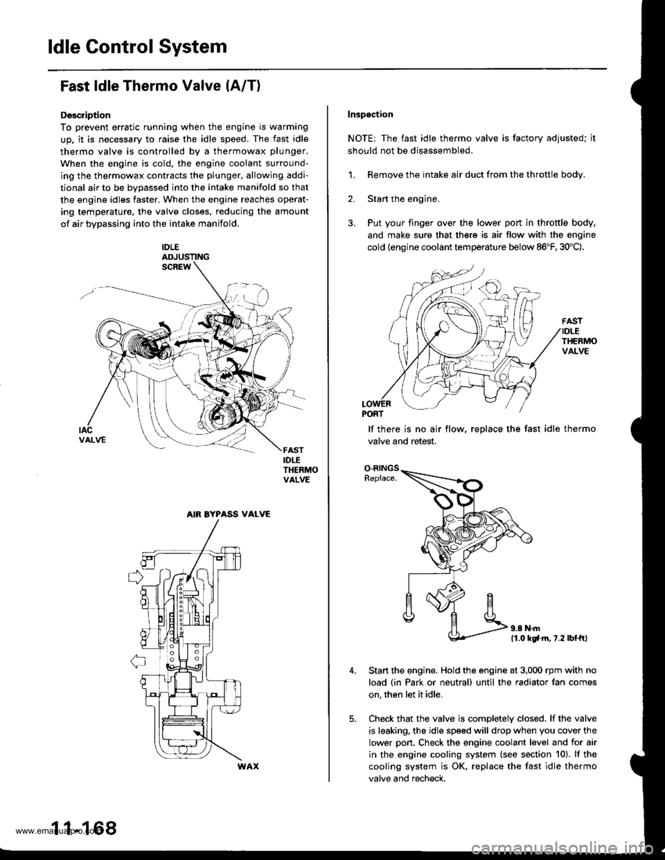
Fast ldle Thermo Valve lA/T)
Description
To prevent erratic running when the engine is warming
up, it is necessary to raise the idle speed. The fast idle
thermo valve is controlled by a thermowax plunger.
When the engine is cold, the engine coolant surround-
ing the thermowax contracts the plunger, allowing addi-
tional air to be bvDassed into the intake manifold so that
the engine idles faster. When the engine reaches operat-
ing temperature. the valve closes, reducing the amount
of air bypassing into the intake manifold.
IDLEADJUSTING
IDLETHERMOVALVE
AIR BYPASS VALVE
11-168
Inspgction
NOTE: The fast idle thermo valve is factory adjusted; it
should not be disassembled.
1. Remove the intake air duct from the throttle body.
2. Start the engine,
3. Put your finger over the lower port in throttle body,
and make sure that there is air flow with the engine
cold (engine coolant temperature below 86"F, 30'C).
lf there is no air flow, replace the fast idle thermo
valve and retest,
O-RINGSReplace.
11.0 kgfl.m, 7.2 lbl.ftl
Start the engine. Hold the engine at 3,000 rpm with no
load (in Park or neutral) until the radiator fan comes
on, then let it idle.
Check that the valve is completely closed. lf the valve
is leaking, the idle speed will drop when you cover the
lower pon. Check the engine coolant level and for air
in the engine cooling system {see section 10). lf the
cooling system is OK, replace the fast idle thermo
valve and recheck.
www.emanualpro.com
Page 382 of 1395
Fuel Supply System
Fuel Injectors {cont'dl
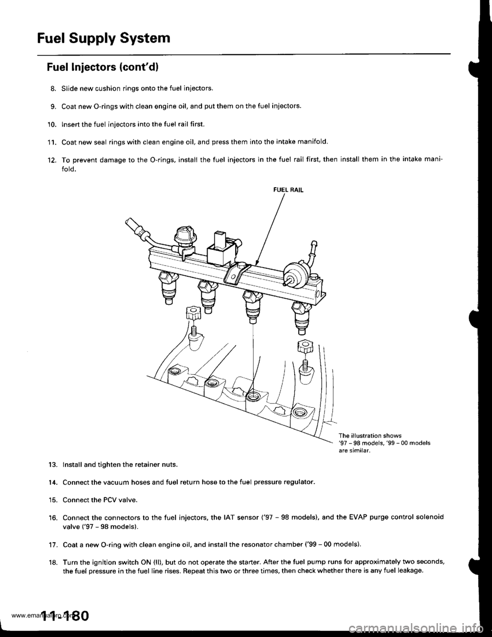
8. Slide new cushion rings onto the fuel injectors.
9, Coat newO-ringswith clean engine oil,and putthem onthefuel iniectors.
'10. lnsert the fuel injectors into the fuel rail first.
11. Coatnewseal ringswithclean engineoil,and press them into the intake manifold
12. To prevent damage to the O-rings, install the fuel injectors in the fuel rail first, then install them in the intake mani-
fold.
FUEL RAIL
The ill!stration shows'97 -98 models,'99 - 00 modelsare similar.
13. lnstall and tighten the retainer nuts.
14. Connect the vacuum hoses and fuel return hose to the fuel pressure regulator.
15. Connect the PCV valve.
16. Connect the connectors to the fuel injectors, the IAT sensor ('97 - 98 models), and the EVAP purge control solenoid
valve {'97 - 98 models).
Coat a new O-ring with clean engine oil, and install the resonator chamber ('99 - 00 models).
Turn the ignition switch ON (ll), but do not operate the starter. After the fuel pump runs for approximately two seconds,
the fuef pressure in the fuel line rises. Repeat this two or three times, then check whether there is any fuel leakage.
11.
18.
1 1-180
www.emanualpro.com