2000 HONDA CR-V air box
[x] Cancel search: air boxPage 342 of 1395
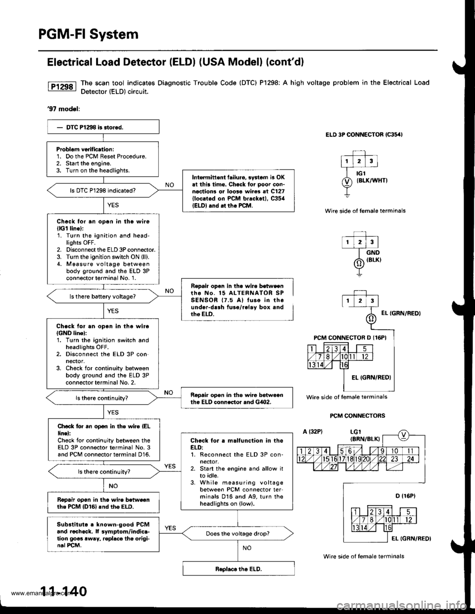
PGM-FI System
Electrical Load Detestor (ELDI (USA Model) (cont'dl
The scan tool indicates Diagnostic Trouble Code {DTC) Pl298; A high voltage problem in the Electrical Load
Detector (ELD) circuit.
97 modsl:
ELD 3P CONNECTOR {C35,'I
Wire sido oI lemale terminals
r lzlrl--T_ow
/6 IBLKI
Y
Repail op€n in th. wire b€tws€ntho No. 15 ALTERNATOR SPSENSOR 17.5 A) tuse in theunder-dlrh fuso/r.lay box andth6 ELD.EL {GRN/NEDI
PCM CONNECTORS
Problam verification:1. Do the PCM Reset Procedure.2. Start the engine.3. Turn on the headlights.Intermittent tailuro, systcm is OK.t this time. Chack for ooor con-noction! or looro wire3 at C127{locaied on PCM brackot), C35{{ELDI and .t tho PCM.
Chack for an opan in tho wilellGl linol:1. Turn thg ignition and head-lights OFF.2. Disconnect the ELD 3P connector.3. Turn the ignition switch ON {ll).4. M6asure voltage b€tw€enbody ground and the ELD 3Pconnoctor terminal No. 1.
Chock lol !n open in the wireIGND linel:'1. Turn the ignition switch andheadlights OFF.2. Disconnect the ELD 3P conneqor,3. Check for continuity betweenbody ground and the ELD 3Pconnector terminal No. 2.
Ropair opon in th6 wi.e betweonth. ELD connector rnd GiO2,
Ch.ck lo. an open in th€ wiro (EL
line):Check for continuity between theELD 3P connector terminal No. 3and PCM connector terminal 016.
Chock for . malfunction in theELD:1. Reconnect the ELD 3P con-neclor,2. Start the engine and allow itto idle.3. While measuring voltagebetween PCM connector terminals 016 and A9. turn theheadlights on (low).
ls there continuityT
R6pafu op6n in tho wire betweenthe PCM {D161snd th6 ELD.
Subltituto . known-good PCMand rachock, f symptom/indic.-tion goes awry, ropl.ce the origi-n.l PCM.
Does the voltage drop?
Wire side of lemale terminals
11-140
Wire side of lemale terminals
www.emanualpro.com
Page 343 of 1395
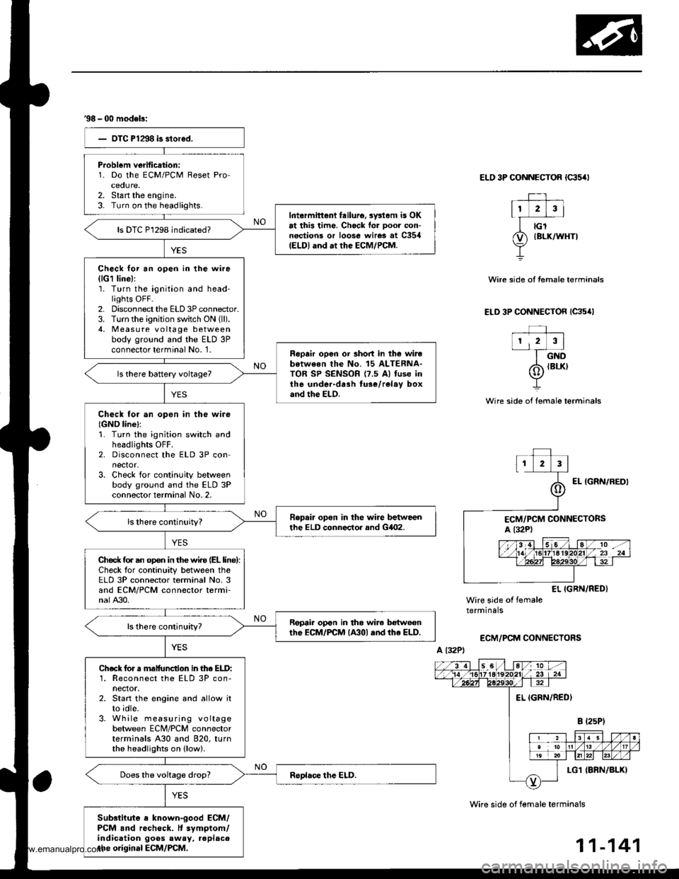
38 - 00 modeb:
Problem verification:1. Do the ECM/PCM Reset Proceoure.2. Stan the engine.3- Turn on the headlights.Intermittent feilure, sysl.m is OKat this time. Check for ooor con-nections or loose wires at C354(ELDI and at the ECM/PCM.
ls DTC P1298 indicated?
Check lor an open in the wire(lG1 line):'1. Turn the ignition and head-lights OFF.2. Disconnect the ELD 3P connector.3. Turn the ignition switch ON (ll).
4, Measu re voltage betweenbody ground and the ELD 3Pconnector terminal No. '1.Reprir open or short in th6 wirebotweon the No. 15 ALTERNA-TOR SP SENSOR {7.5 Al fuse inthe under-drah fuse/relay boxand the ELD.
Check tor an opon in tho wire{GND line}:1. Turn the ignition switch andheadlights OFF.2. Disconnect the ELD 3P connector.3. Check for continuity betweenbody ground and the ELD 3Pconnector terminal No. 2,
Repair opon in the wire betweenthe ELD conneclor and GilO2.
Ched( fo. an op€n in the wir€ (EL linel:Check for continuity between theELD 3P connector terminal No. 3and ECM/PCM connector termi-nalA30.
Repair op€n in tha wile botwecnthe EcM/PCM lA30l .nd rhe ELD.
Check for s malfunction in lhe ELD:1. Reconnect the ELD 3P con-nector.2. Start the engine and allow itto idle.3. While measuring voltagebetween ECM/PCM connectorterminals A30 and 820, turnthe headlights on (low).
Substiiute a known-good ECM/PCM and recheck. It symptom/indication goos away, replacethe original ECM/PCM.
ELO 3P CONNECTOR {c35/rl
Wire side of female terminals
Wire side of female terminals
Wire side ot temale terminals
ELD 3P CONNECTOR {C35,lt
EL IGRN/RED}Wire side of femaletermrnars
ECM/PCM CONNECTORS
A l32P)
11-141
www.emanualpro.com
Page 358 of 1395

ldle Gontrol System
Air Conditioning Signal (cont'dl
(From page 11-'155)
JUMPERWIRE
UNOER.HOOD FUSE/RELAYBOX 9P CONNECTOR tqt52)
123I
56I
ACC IBLK/RWire side ofACC IBLK/REDIWire side of femaletermrnats
A t32PlPCM CONNECTORS C t3rp)
Wire side ol lemale terminals
Ch6ck for an open in th€ wire(ACC linel:Momentarily connect the under-hood fuse/relay box 9P connectorterminal No.5 to body groundwith a jumper wire several times.
ls there a cl;cking noise fromthe 4!/C compressor clutch?
ls there a clicking noise fromthe 4!/C compressor clutch?See air condiiioner inspection{see section 221.
Repai. op6n in the wire betwoenthe PcM (A17) and tho A/Cclutch relay.
Check the A/C operation:1. Start the engine.2. Turn the blower switch ON.3. Turn the A"/C switch ON.
Check for an open in the wire(ACS line):Measure voltage between PCMconnector terminals Ag and C5.
Does the A,/C operate?
Air conditioning signal is OK.
Repair open in the wire betweenthe PCM lCSl and the A/C awitch.ls there less than 1.0 V?
- Subqtitute a known-good FCM.nd r€ch6ck. lt 3ymptom/indi-cation goes awav, replece theoriginal rcM.- Soe th€ eir conditioner in3pec-tion (s6€ aec.tion 22).
www.emanualpro.com
Page 360 of 1395

ldle Control System
Air Gonditioning Signal (cont'd)
JUMPERWIRE
UNDER-HOOD FUSE/RELAYBOX 9P CONNECTOR {G'52I
23a
5589
ACC (BLK/R
Wire side otACC (BLK/RED'
Wire side otfemaleterminals
ECM/PCM CONNECTORS
Wire sid€ of female torminals
(From page '11,157)
Check Ior dn opon in the wiroIACC linel:Momentarily connect the under-hood fuse/relay box 9P connectorterminal No. 5 to body groundwith a jumper wire several times.
ls there a clicking noise lromthe y'y'C compressor clutch?
ls there a clicking noise fromtho A,/C comprossor clutch?Sae rir conditional in3pactionlroa saction 221.
Repai. open in th6 wiro lr€twlanthe ECM/PCM lAl7l .nd tho A/Cclutch rolay.
Check tho op.ration of tho A/C:1. Stan the engine.2. Turn the blower switch ON.3. Turn the Ay'C switch ON.
ChGGk for an open in the wi.eIACS linel:Measure voltage betweon ECM/PCM connector terminals A27and 820.
Does the !y'C operate?
Air conditioning 3ignal i3 OK.
Rap.ir opon in the wir6 bdtunaanrh. Ecil/FcM lA27l rnd rh. A/crwitch.
ls voltage less than 1.0 V?
Sub6lftna a known{ood ECM/PCM and rechock. lf symp-tom/indicetion goes away.roplace the original ECM/rcM.See the ah conditionor inspoc-tion {3e€ section 22},
www.emanualpro.com
Page 368 of 1395
ldle Control System
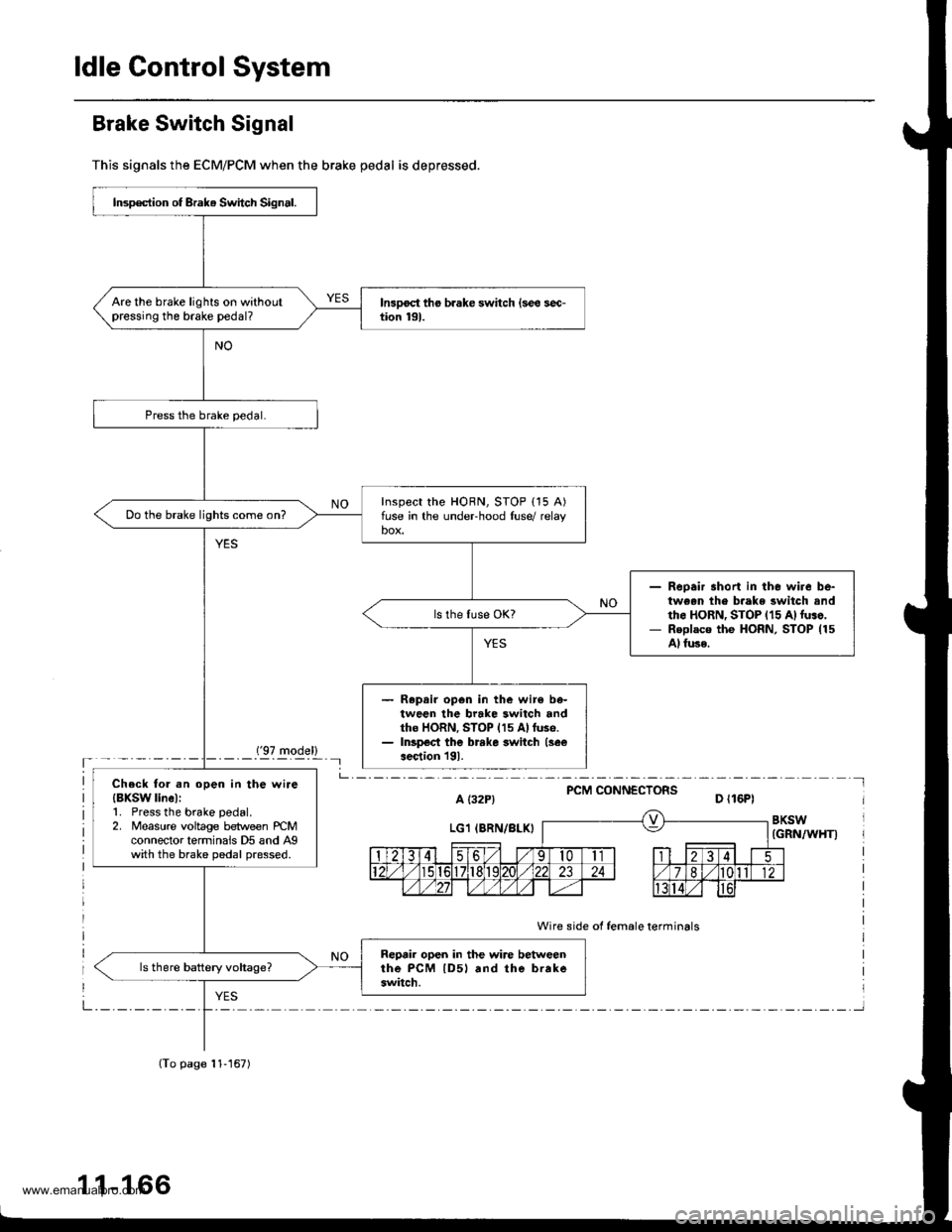
Brake Switch Signal
This signals the ECM/PCM when the brake pedal is depressed.
('97 model)'- - - - -_- Il
PCM CONNECTORSa t32P) D ll6Pl
BKSW(GRN/WHT)
Wire side of female terminals
Insp€ction of Brak. Switch Signal.
Are the brake lights on withoutpressing the brake pedal?
Inspect the HORN, STOP {15 A)fuse in the undeFhood luse/ relaybox.Do the brake lights come on?
Reoair short in the wire be-tween th€ b.ake switch andth6 HoRN, STOP {15 A)luso,Replaco the HoRN, STOP (15
Al fuse.
Repair op6n in the wir€ be-tween the brake switch andtho HORN, STOP (15 Allus6.Inspect the brrke switch (see
aection l9l.
Check tol .n open in the wire{BXSW linel:1. Press the brake pedal.2. Measure voltage between rcMconnector terminais D5 and Agwith the brake pedal pressed.
Reprir open in the wire betweenthe PcM lD5l rnd the brakeswitch.
(To page 11-167)
1 1-166
www.emanualpro.com
Page 371 of 1395
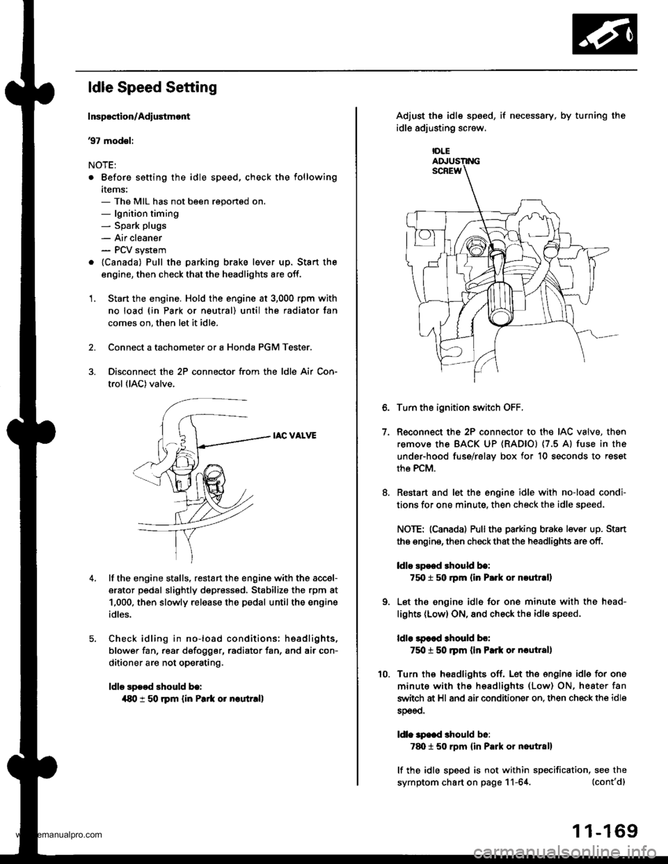
ldle Speed Setting
Inspoction/Adiustmont
37 modsl:
NOTE:
. Before setting the idle speed, check the following
items:- The MIL has not been reportsd on.- lgnition timing- Spark plugs
- Air cleaner- PCV system
. lcanada) Pull the parking brake lever up. Stan the
engine, then check that the headlights are off.
1. Start the engine. Hold the engine at 3,000 rpm with
no load (in Park or neutral) until the radiator fan
comes on, then let it idle.
Connect a tachometer or a Honda PGM Tester.
Disconnect the 2P connector from the ldle Air Con-
trol (lAC) valve.
IAC VALVE
lf the engine stalls, restart the engine with the accel-
erator pedal slightly depr6ss6d, Stabilize the rpm at
1,000, then slowly release the pedal until the engine
idles.
Check idling in no-load conditions: hsadlights,
blower fan, rear d€fogger, radiator fan, and air con-
ditioner are not operating.
ldle spood should b.:
{80 t 50 rpm {in Park or noutr.ll
IDLE
7.
Adjust the idle sp6ed,
idle adjusting screw.
if necessary, by turning the
Turn the ignition switch OFF.
Reconnect the 2P connector to the IAC valve, then
remove the BACK UP (RAD|Ol (7.5 Al fuse in the
under-hood fuse/rslav box for 10 seconds to reset
the PCM.
Restart and let the engine idle with no-load condi-
tions for one minute, then check the idle speed.
NOTE: (Canadal Pullthe parking brake lever up. Stan
the engine, then check that the headlights are off.
ldlo Ep€ed rhould be:
75O t 50 rpm (in P.rk or noutr.ll
Let the engine idl6 for one minute with the head-
lights (Low) ON, and check th€ idl€ speed.
ldle lpcod 3hould bo:
750 t 50 ]pm (in Park or nautlal)
Turn the headlights off. Let th€ engine idle for one
minute with the headlights (Low) ON, heater fan
switch at Hl and air conditioner on. then check the idle
sDeeo.
ldl. specd should b6:
7d) 1 50 rpm {in Park or nautral}
lf the idle speed is not within specification, see the
symptom chart on page 11-64. (cont'd)
1 1-169
www.emanualpro.com
Page 390 of 1395
![HONDA CR-V 2000 RD1-RD3 / 1.G Workshop Manual
Fuel Supply System
PGM-FI Main Relay (contdl
Troubleshooting
lc(}21PGM.FI MAIN RELAY 7P CONNECTOR
GND
trTr]--Flq
FI,TilI A
Y
Wire side ot female terminals
- Engine will not start.- InsDection ol PG HONDA CR-V 2000 RD1-RD3 / 1.G Workshop Manual
Fuel Supply System
PGM-FI Main Relay (contdl
Troubleshooting
lc(}21PGM.FI MAIN RELAY 7P CONNECTOR
GND
trTr]--Flq
FI,TilI A
Y
Wire side ot female terminals
- Engine will not start.- InsDection ol PG](/manual-img/13/5778/w960_5778-389.png)
Fuel Supply System
PGM-FI Main Relay (cont'dl
Troubleshooting
lc(}21PGM.FI MAIN RELAY 7P CONNECTOR
GND
trTr]--Flq
FI,Til'I A
Y
Wire side ot female terminals
- Engine will not start.- InsDection ol PGM-FI mainrelay and relay harness,
Check fo. an open in the wireIGND linol:1. Turn the ignition switch OFF.2. Disconnect the PGM Fl mainrelay 7P connector.3. Check for continuity betweenthe PGM'FI main relay 7P con-nector terminal No. 3 and bodyground.
Repair opcn in th€ wire betweenthe PGM-FI main relav and G101.
Check tor an open or short in thewiro (BAT line):Measure voltage between thePGM'FI main relay 7P connectorterminal No. 7 and body ground.- Repai. open or short in lhewir6 belween the PGM-FImain relay and the Fl E/M (15Al fu3e.- Replace th6 FIE/M (15 Altus6in th€ under-hood fuse/.6lay
ls there baftery voltage?
Check lor an open or short in thewire (lGl line):L Turn the ignition switch ON (ll).2. Measure the voltage betweenthe PGM-FI main relay 7P connectorterminal No. 5 and bodyground.- Repair open or shorl in thewire between the FGM-FI mainrelay and the No. 13 FUELPUMP 115 A) tuse.- Replaco the No. 13 RJEL PUMP115 A) luse in the und6.-d$hfuso/ relav box.Check for an open or short in thewire {STS line):1. Turn the ignition switch to theSTART (lll) position.NOTE:. M/T: Clutch pedal must bedepressed.. A/T: Transmission in E orElposition.2. Measure the voltage betweenthe PGM-Fl main retay 7Pconnector terminal No. 2 andbody ground.- Repair open or short in thewire betwe€n the PIGM-FI m.inrclay and th€ No. 31 STARTERSlGllAL 17.5 A) tuse.- Repl.ce the No. 31 STARTERSIGNAL 17.5 Al tuse in theunder-dash tuse/relay box.('97 model: To page 11-189)('98 00models:To page 1l 190)
1 1-188
www.emanualpro.com
Page 405 of 1395
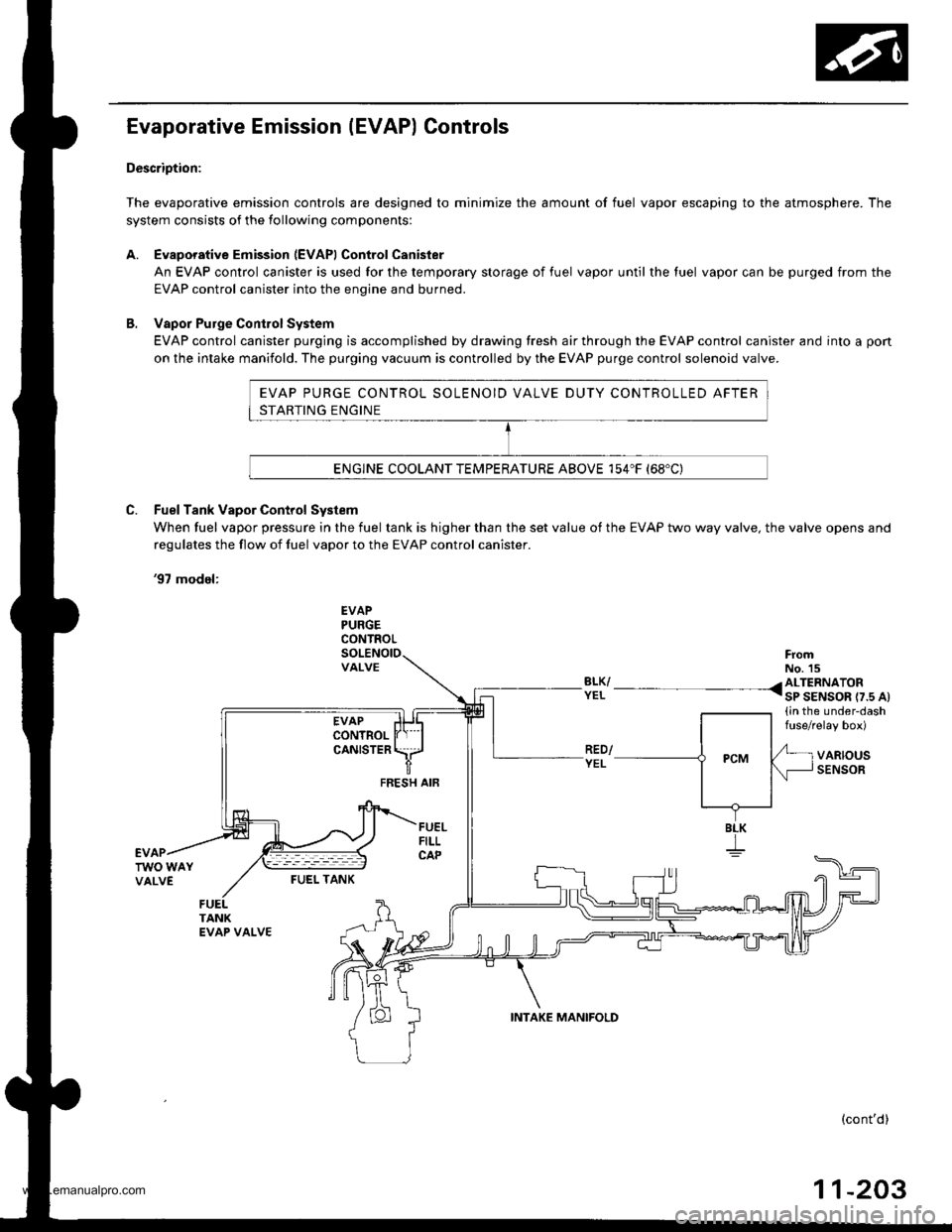
EVAP PURGE CONTROL SOLENOID VALVE DUTY CONTROLLED AFTER
STARTING ENGINE
ENGINE COOLANT TEMPERATURE ABOVE 154"F (68'C)
Evaporative Emission (EVAP) Controls
Description:
The evaporative emission controls are designed to minimize the amount of fuel vapor escaping to the atmosphere. The
system consists of the following components:
A. Evaporative Emission (EVAPI Control Canister
An EVAP control canister is used for the temporary storage of fuel vapor until the luel vapor can be purged from the
EVAP control canister into the enqine and burned.
B. Vapor Purge ConirolSystem
EVAP control canister purging is accomplished by drawing fresh air through the EVAP control canister and into a pon
on the intake manifold. The purging vacuum is controlled by the EVAP purge control solenoid valve.
C. Fuel Tank Vapor Control System
When fuel vapor pressure in the fuel tank is higher than the set value of the EVAP two way valve, the valve opens and
regulates the flow ot fuel vapor to the EVAP control canister.
'97 model:
EVAPPURGECONTROL
VALVEFromNo. 15BLK/ /ALTERNATORYEL I sP SENSOR r7.s At(in the under-dashfuse/relay box)
VARIOUSSENSORFEESH AIF
BLK
I
FUEI- TANK
(cont'd)
11-203
INTAKE MANIFOLD
www.emanualpro.com