Page 934 of 1395

Front Brake Pads
Inspection and Replacement (cont'dl
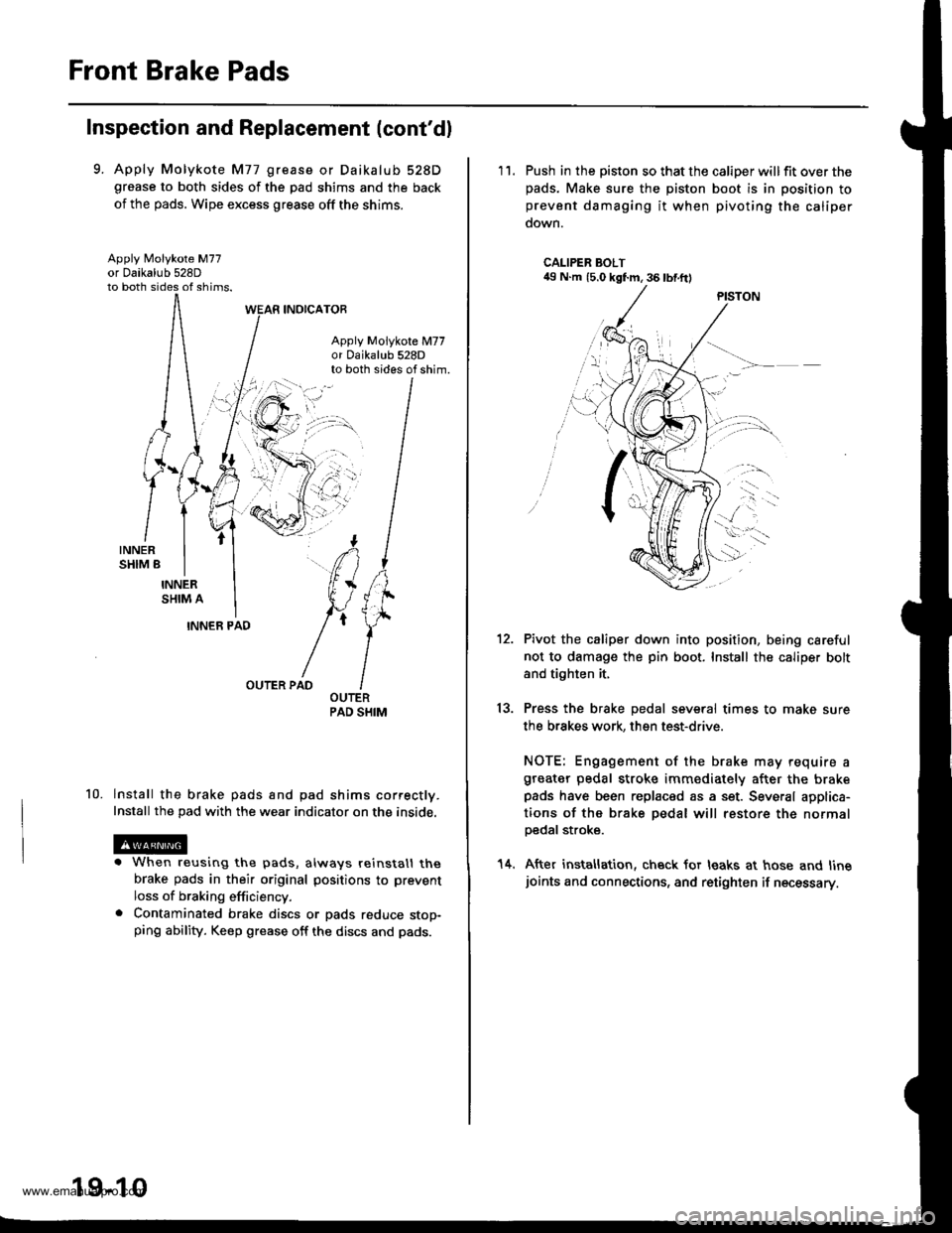
9. Apply Molykote M77 grease or Daikalub 528Dgrease to both sides of the pad shims and the back
of the pads. Wipe excess grease off the shims.
Apply Molykote M77
to both sides of shims.
INOICATOR
Apply Molykote M77or 0aikalub 528Dto both sides of shim.
10.
INNER PAD
OUTER PAD
lnstall the brake pads and pad shims correctly.
Install the pad with the wear indicator on the inside.
. When reusing the pads, always reinstall thebrake pads in their original positions to prevent
loss of braking efficiency.. Contaminated brake discs or pads reduce stop-ping ability. Keep grease off the discs and pads.
19-10
'11. Push in the piston so that the caliper willfit over thepads. Make sure the piston boot is in position toprevent damaging it when pivoting the caliper
down.
CALIPER BOLT49 N.m (5.0 kgf.m, 36 lbf.ftl
13.
Pivot the caliper down into position, being careful
not to damage the pin boot. Install the caliper bolt
and tighten it,
Press the brake pedal several times to make sure
the brakes work, then test-drive.
NOTE: Engagement of the brake may require agreater pedal stroke immediately after the brakepads have been replaced as a set. Several applica-
tions of the brake pedal will restore the normalpedal stroke.
After installation, check for leaks at hose and linejoints and connections, and retighten if necessary.
14.
www.emanualpro.com
Page 936 of 1395

Front Brake Caliper
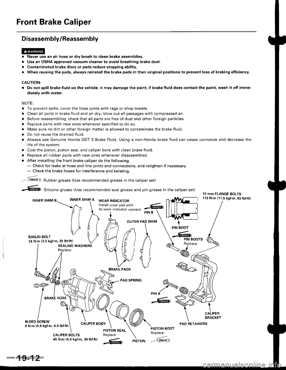
Disassembly/Reassembly
. Never use an air hose or dry brush to clean brake assemblies.
. Use an OSHA approved vacuum cleaner to avoid breathing brake dust.
. Contaminated brake discs or pads reduce stopping ability.
. When reusing the pads, always reinstallthe brake pads in their original positions to prevent loss ol braking efficiency.
CAUTION:
. Do not spill brake fluid on the vehicle; it may damage the paint; if brake fluid does contact the paint, wash it off imme-
diatelY with water.
NOTEI
. To prevent spills, cover the hose joints with rags or shop towels.
. Clean all pans in brake fluid and air dry; blow out all passages with compressed air.
. Before reassembling, check that all parts are free of dust and other foreign particles.
. Replace parts with new ones whenever specified to do so.
. Make sure no dirt or other foreign matter is allowed to contaminate the brake fluid.
. Do not reuse the drained fluid.
. Always use Genuine Honda DOT 3 Brake Fluid. Using a non-Honda brake fluid can cause corrosion and decrease the
life of the system.
. Coat the piston, piston seal, and caliper bore with clean brake fluid.
. ReDlace all rubber oarts with new ones whenever disassembled.
. After installing the front brake caliper do the following.- Check for leaks at hose and line joints and connections, and retighten if necessary.- Check the brake hoses for interference and twistinq.
SHIM
12 mm FLANGE BOLTS113 N.m (11.5 kgtm,83lbf.ftlINNER
ft
il1
#
\i
#
PIN B
OUTER PAO SHIM
PAD SPRING
IPIN BOOT
-Cr
SEALING WASHERSReplace.4dd*
ERAKE PADS
'f,-rre
/ tto*l "o"\
t@I
/\'
sLreo 6cnew \I N m 10.9 kStm, 6.5 lbnft)
\
6-
>PIN A
-6, {
CALIPER BOOY
CALIPER EOLTS49 N.m {5.0 kgl.m, 36lbf.ftl
PISTON AOOTReplace.
"..-a=a-...,--"sEqriPISTON
t".:jil,,.'.1!!!!9!il: Rubber grease (Use recommended grease in the caliper set)
irf"i:;;T::fl,-J'I",0 .@
--6, Silicone grease (use recommended seal grease and p,n grease in the caliper set)
INNER SHIM BWEAB INDICATOR
EANJO BOLT34 N.m {3.5 kgf m,25 lblftl
PISTON SEALReplace.
AFACKET
19-12
PAD RETAINERS
www.emanualpro.com
Page 1325 of 1395

Troubleshooting
Erasing the DTC Memory
To erase the DTC{S) from the SRS unit, use a Honda
PGM Tester (see the Honda PGM Tester SRS Vehicle
System Supplement) or the following procedure.
1. Make sure the ignition switch is OFF.
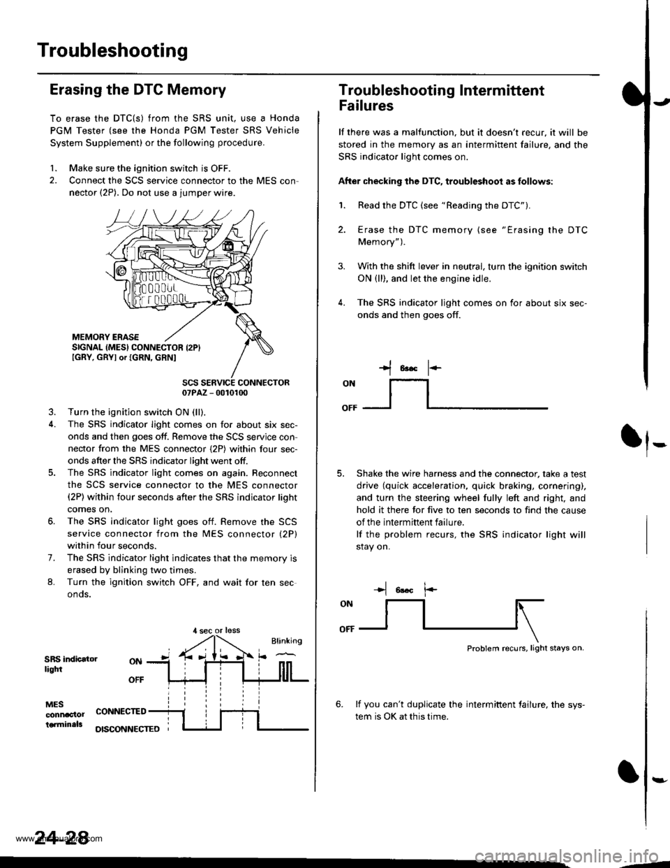
2. Connect the SCS service connector to the MES con,
nector (2P). Do not use a jumper wire.
MEMORY ERASESIGNAL (MES} CONNECTOR I2PIIGRY, GRYI or IGRN, GRNI
SCS SERVICE CONNECTOR07PAZ - 0010100
3. Turn the ignition switch ON (ll),
4. The SRS indicator light comes on for about six sec-
onds and then goes off. Remove the SCS servjce con
nector from the MES connector {2P) within four sec-
onds after the SRS indicator light went otf.
5. The SRS indicator light comes on again. Reconnect
the SCS service connector to the MES connector(2P) within four seconds after the SRS indicator lioht
comes on,
6. The SRS indicator light goes otf. Remove the SCS
service connector from the MES connector (2P)
within four seconds.
7. The SRS indicator light indicates that the memory is
erased by blinking two times.
L Turn the ignition switch OFF, and wait for ten sec
onos.
SRS indicatorliqtfi
MESconnac'lolterminals
OFF
CONNECTED
OISCONNECTEO
24-28
,l sec or less
3.
Troubleshooting Intermittent
Failures
lf there was a malfunction. but it doesn't recur, it will be
stored in the memory as an intermittent failure, and the
SRS indicator light comes on.
After checking the DTC, troubleshoot as follows:
1. Read the DTC (see "Reading the DTC").
4.
Erase the DTC memory (see "Erasing the DTC
Memory").
With the shift lever in neutral, turn the ignition switch
ON (ll), and let the engine idle.
The SRS indicator ljght comes on for about six sec-
onds and then goes off.
t*F
ON
lt--- _l
Shake the wire harness and the connector, take a test
drive (quick acceleration, quick braking, cornering),
and turn the steering wheel fully left and right, and
hold it there for five to ten seconds to find the cause
of the intermittent failure.
lf the problem recurs, the SRS indicator light will
stay on.
-+t 6!.c l.-
Problem recurs, light stays on.
6. lf you can't duplicate the intermiftent tailure, the sys-
tem is OK at this time.
:-
-4
www.emanualpro.com