Page 886 of 1395
Valve Body Unh Roa$embly
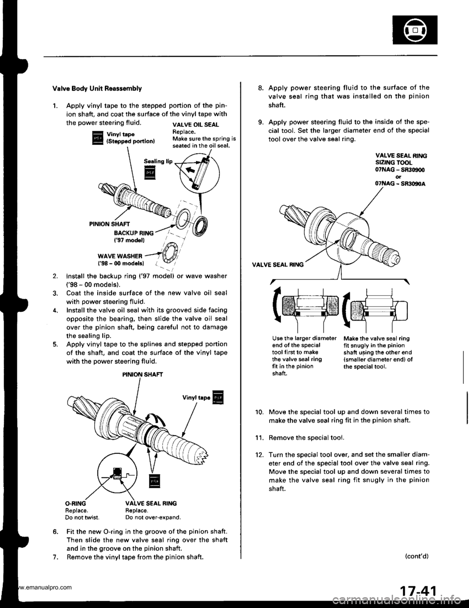
1. Apply vinyl tape to the stepped portion of the pin-
ion shaft, and coat the surface of the vinyl tape with
the power steering fluid.
Vinyl tape(Stopp6d portion)
VALVE OIL SEALReplace.Make sure the spring isseated in the oil seal.
Serling
E
7.
PINION SHAFT
BACKUP RING137 modell
WAVE WASHER{'98 - 00 modelsl
Install the backup ring {'97 model) or wave washer
('98 - 00 models).
Coat the inside surface of the new valve oil seal
with power steering fluid.
Install the valve oil seal with its grooved side facing
opposite the bearing, then slide the valve oil seal
over the pinion shaft, being careful not to damage
the sealing lip.
Apply vinyl tape to the splines and stepped ponion
of the shaft, and coat the surface of the vinyl tape
with the power steering fluid.
Vinyl trp€
O.RINGReplace.Do not twist.R€place-Do not over-expand.
Fit the new O-ring in the groove of the pinion shaft.
Then slide the new valve seal ring over the shaft
and in the groove on the pinion shaft,
Remove the vinyl tape from the pinion shaft.
\/
PINION SHAFT
8.Apply power steering fluid to the surface of the
valve seal ring that was installed on the pinion
shaft.
Apply power steering fluid to the inside of the spe-
cial tool. Set the larger diameter end of the special
tool over the valve seal ring.
VALVE SEAL RINGSIZNG TOOL07NAG - SR309q'ot07NAG - SR3oltoA
Mak€ the valve seal ringfit snugly in the pinion
shatt using th6 other end{smaller diameter end) otthe special tool.
10.
11.
12.
Move the special tool up and down several times to
make the valve seal ring fit in the pinion shaft,
Remove the soecial tool.
Turn the special tool over, and set the smaller diam-
eter end of the specisl tool over the valve seal ring.
Move the special tool up and down several times to
make the valve seal ring fit snugly in the pinion
shaft.
(cont'd)
lrr.rj1
tffifrE-rr.]
r\-''] 7
Usg th6 larg€r diameterend of the specialtoollirst to maketh€ valve seal ringtit in the pinion
shaft.
17-41
www.emanualpro.com
Page 888 of 1395
20. Press the new bearing into the valve housing with
the stamped letter facing up using a hydraulic press
and soecialtool.
ATTACHMENT,32x35mm07746 - 0010100
- ROLLER BEARINGLetter stamped face
21. Apply vinyl tape to the pinion shaft, then coat the
vinyltape with power steering fluid.
Sealing lip tace.VALVE OIL SEAL
VALVE HOUSING
SHAFT
SLEEVE SEAL
PINION
E
22, Insert the pinion shaft into the valve housing. Be
careful not to damage the valve seal rings.
23. Remove the vinyl tape from the pinion shaft, then
remove any residue from the tape adhesive.
8e sure that theseal rings are notturned up, theninstall.
DRIVER
24. Press the pinion shaft/sleeve using a hydraulic
press. Check that the pinion shaft/sleeve turns
smoothly by turning the pinion shaft,
(cont'd)
17-43
www.emanualpro.com
Page 891 of 1395
Power Steering Gearbox
Reassembly (cont'dl
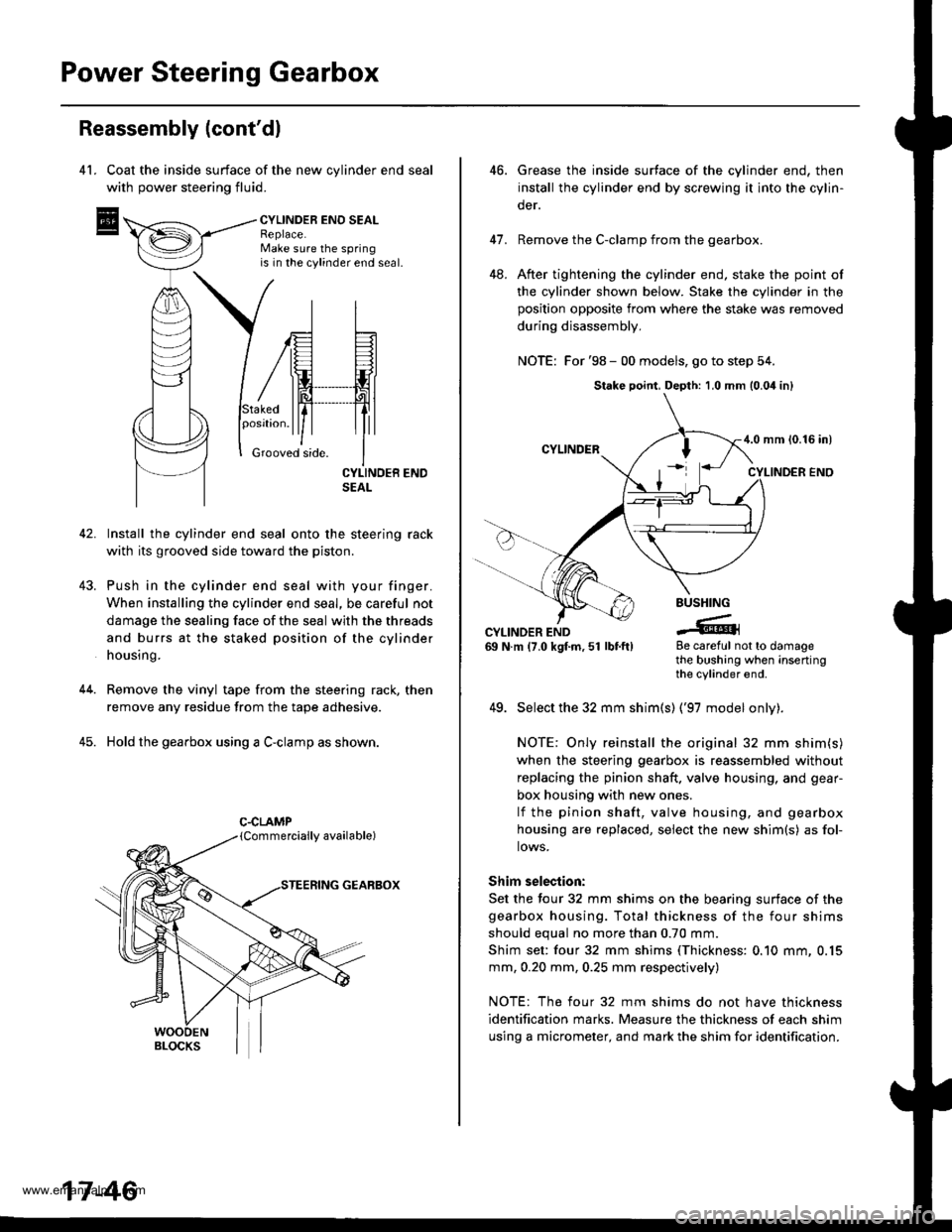
4l. Coat the inside surface of the new cvlinder end seal
with power steering fluid.
CYLINDEB ENO SEALReplace.Make sure the springis in the cylinder end seal.
43.
Stakedposrtron.
Grooved side.
42. Install the cylinder end seal onto the steering rack
with its grooved side toward the piston.
Push in the cylinder end seal with your finger.
When installing the cylinder end seal, be careful not
damage the sealing face of the seal with the threads
and burrs at the staked position of the cylinder
housing.
Remove the vinyl tape from the steering rack, then
remove any residue from the tape adhesive.
Hold the gearbox using a C-clamp as shown.
GEARBOX
44.
45.
C.CLAMP
17-46
46.Grease the inside surtace of the cylinder end, then
install the cylinder end by screwing it into the cylin-
der.
Remove the C-clamp from the gearbox.
After tightening the cylinder end, stake the point of
the cylinder shown below. Stake the cylinder in the
position opposite from where the stake was removed
during disassembly,
NOTE: For '98 - 00 models, go to step 54.
41.
48.
BUSHING
-tGCYLINDER END69 N.m (7.0 kgf.m,51 lbtft)8e careful not to damagethe bushing when insertingthe cylinder end.
49. Select the 32 mm shim(s) ('97 model onlv).
NOTE: Only reinstall the original 32 mm shim(s)
when the steering gearbox is reassembled without
replacing the pinion shaft. valve housing, and gear-
box housing with new ones.
lf the pinion shaft, valve housing, and gearbox
housing are replaced, select the new shim{s) as fol-
lows.
Shim selection:
Set the four 32 mm shims on the bearing surface of the
gearbox housing. Total thickness of the four shims
should equal no more than 0.70 mm.
Shim set: four 32 mm shims (Thickness: 0.10 mm, 0.15
mm, 0.20 mm, 0.25 mm respectively)
NOTE: The four 32 mm shims do not have thickness
identification marks. Measure the thickness of each shim
using a micrometer, and mark the shim for identification.
Stake point, Depth: 1,0 mm (0.04 inl
4.0 mm {0.16 in)
www.emanualpro.com
Page 892 of 1395
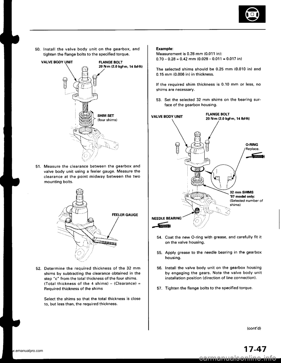
50. Install the valve body unit on the gearbox. and
tighten the flange bolts to the specified torque.
VALVE BODYFLANGE BOLT20 N.m 12.0 kgt.m, 14lbtft)
ct.
SHIM SET(four shims)
Measure the clearance between the gearbox and
valve body unit using a feeler gauge. Measure the
clearance at the poinl midway between the two
mounting bolts.
GAUGE
Determine the required thickness of the 32 mm
shims by subtracting the clearance obtained in the
step "c" from the total thickness of the four shims.
(Total thickness of the 4 shims) - (Clearance) =
Reouired thickness of the shims
Select the shims so that the total thickness is close
to, but less than, the required thickness.
Example:
Measurement is 0.28 mm (0.011 in);
0.70-0.28=0.42 mm (0.028-0.011 = 0.017 in)
The selected shims should be 0,25 mm (0.010 inl and
0.15 mm (0.006 in) in thickness.
lf the required shim thickness is 0.10 mm or less, no
shrms are necessary.
53. Set the selected 32 mm shims on the bearing sur-
face of the gearbox housing.
VALVE BODY UNITla lbl.frl
Coat the new O-ring with grease, and carefully fit it
on the valve housing.
Apply grease to the needle bearing in the gearbox
housing.
Install the valve body unit on the gearbox housing
by engaging the gears. Note the valve body unit
installation position (direction of line connection).
Tighten the flange bolts to the specified torque.
(cont'd)
FLANGE BOLT20 N.m (2.0 kgf.m,
/a)E?
E
O.RINGReplace.
-6{
NEEDLE BEARING
-6lr
54.
56.
57.
17-47
www.emanualpro.com
Page 899 of 1395
Suspension
Special Tools ............. 18-2
Component Locations
lndex ................ ...... 18-3
Wheel Alignment
Service lnformation ......................,.. 18-4
Camber .................. 18-4
Caster ............... ...... 18-5
Front Toe Inspection/
Adiustment ........ 18-5
Rear Toe Inspection/
Adiustment ........ 18-6
Turning Angle Inspection/
Adiustment ........ 18-6
Wheel/Hub Inspection
Bearing End Play .......................,...... 18-7
Wheel Runout ....... 18-7
Front Suspension
Suspension Arms Replacement ..... 18-8
Knuckle/Hub Replacement ............. 18-9
Lower Ball Joint Replacement ....... 18-15
Ball Joint Boot Replacement .......... 18-16
Front Damper
Removal ................. 18-16
Disassembly/lnspection .................. 18-1 7
Reassembly ........... 18-18
lnstallation ............. 18-18
Rear Suspension
Suspension Arms Replacement ..... 18-19
Hub Bearing Unit Replacement ...... 18-20
Upper Arm Bushing
Replacement ..... 18-23
Rear Damper
Removal ................. 18-23
Disassembly/1nspection .................. 18-24
Reassembly ........... 18-25
lnstallation ............. 18-25
www.emanualpro.com
Page 905 of 1395
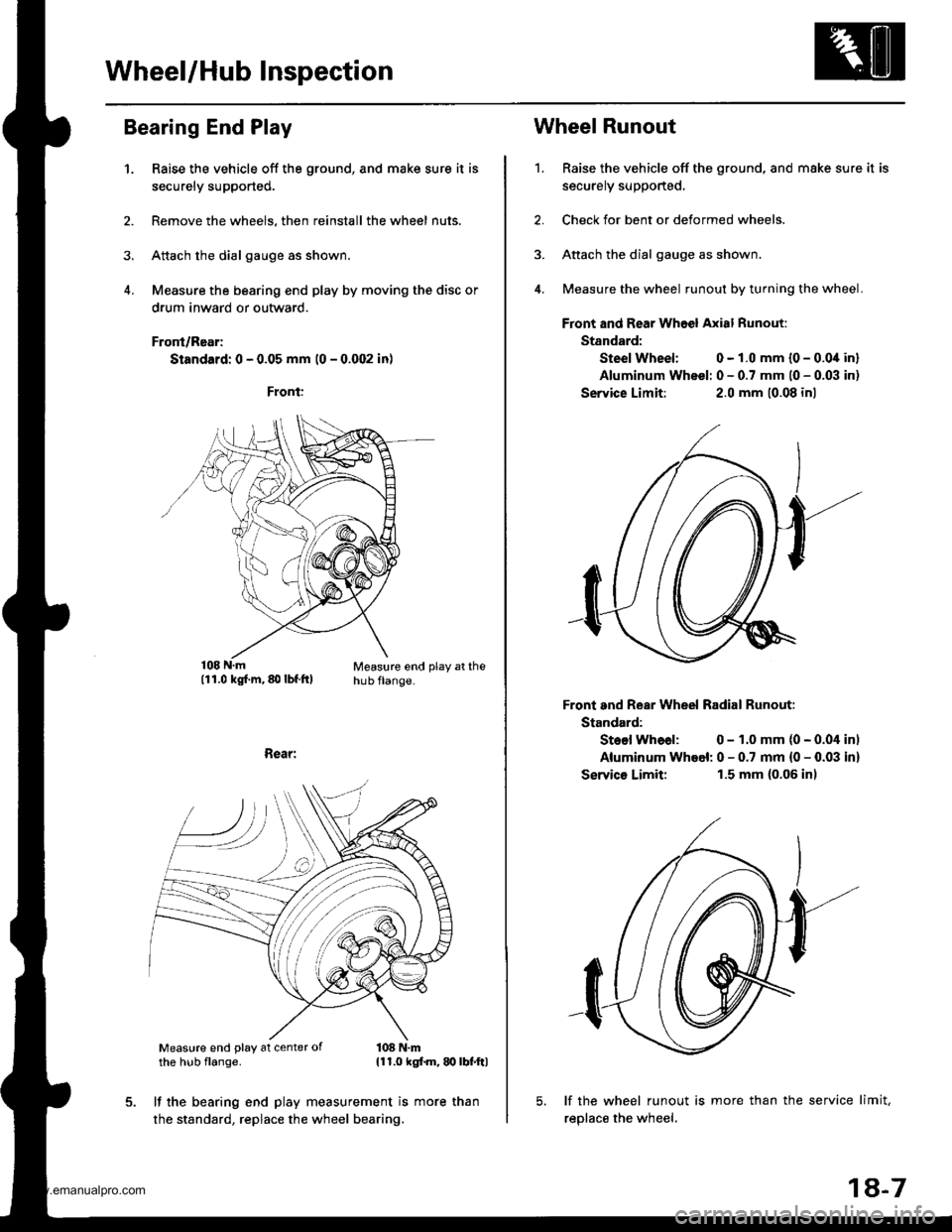
Wheel/Hub lnspection
Bearing End Play
1.Raise the vehicle off the ground, and make sure it is
securely supported.
Remove the wheels, then reinstall the wheel nuts.
Attach the dial gauge as shown.
Measure the bearing end play by moving the disc or
drum inward or outward.
Front/Rear;
Standard: 0 - 0.05 mm (0 - 0.002 in)
Measure end play at thehub flange.
Rear:
Measure end play at center ofthe hub flange.108 N.m{11.0 kgf.m, q} lbf.ftl
It the bearing end play measurement is more than
the standard, replace the wheel bearing.
1.
Wheel Runout
Raise the vehicle off the ground, and make sure it is
securely supported,
Check for bent or deformed wheels.
Attach the dial gauge as shown.
Measure the wheel runout by turning the wheel.
Front and Rear Whoel Axial Runout:
Standard:
Steel Wheel: 0 - 1.0 mm {0 - 0.0i[ in]
Aluminum Wheel: 0 - 0.7 mm l0 - 0.03 in)
Service Limit:2.0 mm 10.08 inl
Front and Rear Wheel Radial Runout:
Standard:
Steel Whoal: 0 - 1.0 mm (0 - 0.04 inl
Aluminum Whoel: 0 - 0.7 mm {0 - 0.03 in}
Servics Limit:1.5 mm (0.06 inl
lf the wheel runout is more than the service limit,
reolace the wheel.
18-7
www.emanualpro.com
Page 907 of 1395
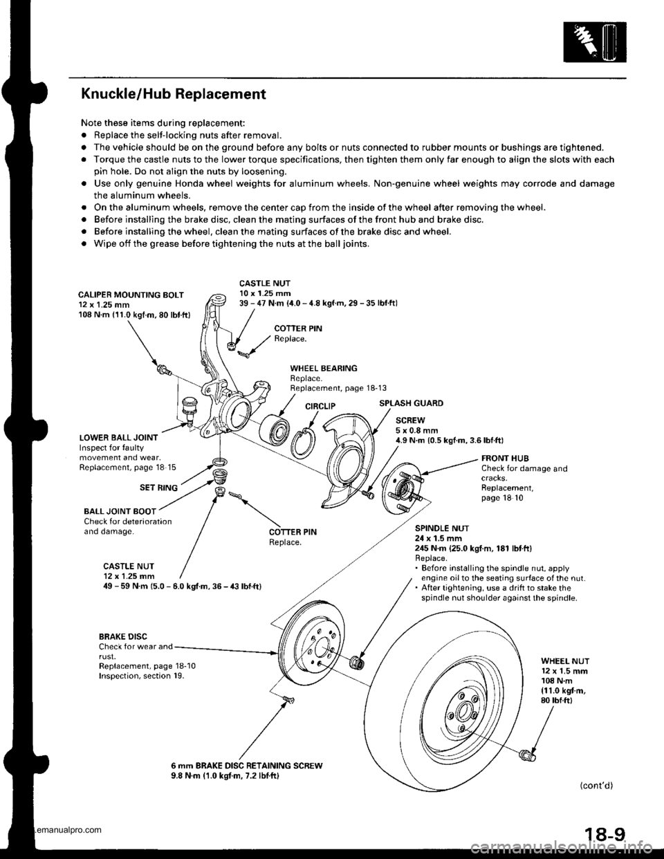
Knuckle/Hub Replacement
Note these items during replacement:
. Replace the selt-locking nuts after removal.
. The vehicle should be on the ground before any bolts or nuts connected to rubber mounts or bushings are tightened.
. Torque the castle nuts to the lower torque specifications, then tighten them only far enough to align the slots with each
pin hole. Do not align the nuts by loosening.
o Use only genuine Honda wheel weights for aluminum wheels. Non'genuine wheel weights may corrode and damage
the aluminum wheels.
. Onthealuminum wheels, remove the center cap from the inside of the wheel after removing the wheel.
. Before installing the brake disc, clean the mating surfaces of the front hub and brake disc.
. Before installing the wheel. clean the mating surfaces ofthe brake disc and wheel.
. Wipe off the grease before tightening the nuts at the balljoints.
CALIPER MOUNTING BOLT12 x 1.25 mm108 N.m (11.0 kgtm.80 lbt.ftl
LOWER BALL JOINTInspect for faultymovement and wear,Replacement, page'18 15
CASTLE NUT10 x 1.25 mm39 - 47 N.m (i1.0 - 4.8 kgf.m, 29 - 35 lbf.ftl
COTTER PINReplace.
WHEEL BEARINGBeplace.Replacement, page 18-13
CIRCLIPSPLASH GUARD
SCREW5x0.8mm4.9 N.m {0.5 kgf.m,3.6lbf.ft)
SET RING
FRONT HUBCheck for damage and
Replacement,page 18 10
BALL JOINT BOOTCheck for deteriorationano oamage.SPINOLE NUT24 x 1.5 mm245 N.m {25.0 kgI.m, 181 lbtft}Replace.. Before installing the spindle nut, applyengine oil to the seating surface of the nut.. After tightening, use a drift to stake thespindle nut shoulder against the spindle.
COTTER PINReplace.
CASTLE NUT12x 1.25 fim49 - 59 N.m 15.0 - 6.0 kgt.m. 36 - € lbf.ft)
BRAKE DISCCheck for wear andrust.Replacement, page 18-10Inspection, section 19.
WHEEL NUT12 x 1.5 mm108 N.m{11.0 kgt m,80 tbf.ftl
6 mm BRAKE DISC RETAINING SCREW9.8 N.m (1.0 kgtm, 7.2 lbtftl(cont'd )
18-9
www.emanualpro.com
Page 911 of 1395
27. Separate the hub from the knuckle using the special
tool and a hydraulic press. Take care not to distort
the splash guard. Hold on to the hub to keep it from
falling when pressed clear.
HUB DIS/ASSEMELY TOOL07GAF - 5800100
FRONT HUB
SETTINGPOINT
Remove the circlip and the splash guard from the
knuckle.
28.
Check for bending and damage.
29. Press the wheel bea.ing outofthe knuckle using the
soecialtools and a Dress.
DRIVER077,19 - 0010000
ORIVERATTACHMENT,62x64mm07947 - 6340400
30. Press the wheel bearing inner race from the hub
using the special tool, a bearing separator, and a
press.
HU8 OIS/ASSEMBLY TOOL07GAF - SE00100
EEARINGSEPARATORO-1112in.(Commercially available)
{cont'd}
18-13
www.emanualpro.com