2000 HONDA CR-V No start
[x] Cancel search: No startPage 496 of 1395

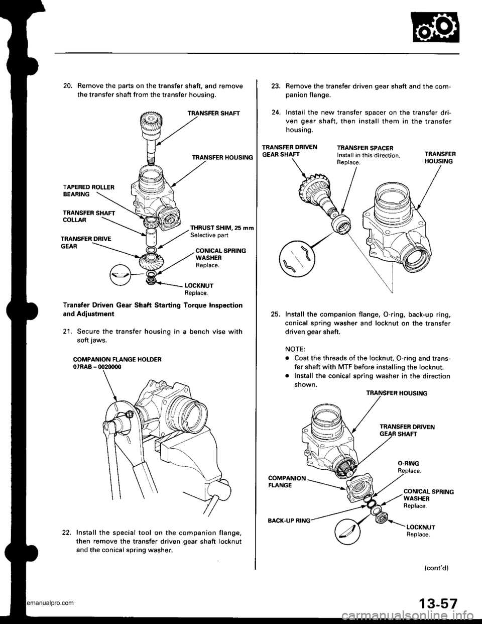
20. Remove the parts on the transfer shaft, and remove
the transfer shatt from the transfer housinq.
TRANSFER SHAFT
TRANSFER HOUSING
TAPERED ROLLERBEARING
TRANSFER SHAFTCOLLAR
TMNSFER DRIVEGEAR
THRUST SHIM, 25 mmSelective part
CONICAL SPRINGWASHERReplace.
LOCKNUTReplace.
Transter Driven Gear Shaft Starting Torque Inspection
and Adlustment
21. Secure the transfer housing in a bench vise with
soft iaws.
Install the special tool on the companion flang€,
then remove the transfer driven gear shaft locknut
and the conical spring washer.
COMPANION FLANGE HOLDER
22.
BACK.UP
Remove the transter driven gear shaft and the com-
panion flange.
Install the new transfer spacer on the transfer dri-
ven gear shaft, then install them in the transfer
housing.
TRANSFER DRIVENGEAR SHAFTTRANSFER SPACERInstall in this direction.TRANSFER
25.Install the companion flange, O-ring, back-up ring,
conical spring washer and locknut on the transfer
driven gear shaft.
NOTE:
. Coat the threads of the locknut, O-ring and trans-
fer shaft with MTF before installing the locknut.
. Install the conical spring washer in the direction
shown.
TRANSFER HOUSING
O.RING
COMPANIONFLANGECONICAL SPRINGWASHERReplace.
LOCKNUTReplace.
(cont'd)
13-57
www.emanualpro.com
Page 497 of 1395

Transfer Assembly
Reassembly (cont'dl
26. Secure the transfer housing in a bench vise with
soft jaws.
COMPANION FLANGE HOLDER07RAB - 002tD00
27. Install the special tool on the companion flange.
then tighten the transfer driven gear shaft locknut
while measuring the starting torque of the transfer
driven gear shaft.
STARTING TOROUE:
0.98 - 1.39 N.m
{10.0 - 1i1.2 kgf.cm, 8.68 - 12.3 lbf in}
TIGHTENING TOROUE:
132 - 216 N.m
(13.5 - 22.0 kgf.m, 97.6 - 159 lbf.ft)
NOTE:
. Rotate the companion flange several times to
seat the tapered roller bearing, then measure the
startrng torque.
. lf the starting torque exceeds 1.39 N.m (14.2
kgf.cm, 12.3 lbf.in), .eplace the transfer spacer
and reassemble the parts. Do not adjust the
torque with the locknut loose.
. lf the tightening torque exceeds 216 N.m (22.0
kgf.m, 159 lbf'ft), replace the transfer spacer and
reassemble the parts.
. Write down the measurement of the starting
torque: it is used to measure the total starting
torque.
28. Stake the locknut into the transfer driven oear shaft
using a 3.5 mm punch.
0.7 - 1.2 mm(0.03 - 0.05 inl
Point to bestaked.
Install the transfer shaft assemblv in the transfer
housing, then install the tapered roller bearing,
transfer shaft collar, 25 mm thrust shim, transfer
drive gear, conical spring washer, and transfer shaft
locknut on the transfer shaft.
NOTE:
. Coat the threads of the locknut and transfer shaft
with MTF before installing the locknut.
. lnstall the conical spring washer in the direction
snown.
TMNSFER SHAFTASSEMBLY
TRANSFER HOUSING
TAPERED ROLLERBEARING
TRANSFER SHAFTCOLLAR
TRANSFER DRIVEGEAR
PUNCH3.0-3.5 mm10.12 - 0.1a inl
THRUST SHIM, 25 mmSelective part
CONICAL SPRINGWASHEBReplace.
LOCKNUTReplace.
29.
www.emanualpro.com
Page 498 of 1395

30. Hold the transfer shaft with a 14 mm Allen wrench
clamDed in a bench vise.
NOTE: The locknut has left-hand threads.
TOROUE: 118 N.m (12.0 kgt'm,86.8 lbf'ft)
31. Stake the locknut on the transfer shaft using a 3.5
mm Dunch.
PUNCH3.0 - 3.5 mm{0.12 - 0.14 inl
14 mm ALLEN WRENCH
Totsl Starting Torquo Inspoction and Adiustment
32. Temoorarilv install transfer cover A without the O-
ring.
TRANSFER HOUSING
TRANSFER COVER A
oEl
€lE/Ehvc/E\\g8 x 1 .25 mm24 N.m (2.4 kg{ m, 17 lbtftl
5t.Secure the transfer housing in a bench vise with
soft jaws. then rotate the companion flange several
times to fit the tapered roller bearing,
TOROUE WR€NCH
34. Measure the total starting torque.
TOTAL STARNNG TOROUE:
1.70 - 2.08 N.m 117.3 - 21.2 kgf.cm, 15.0 - 18.i1 lbf inl
+ Transter Driven Gear Shaft Starting Torque Value
(wrot€ down in step 27).
(cont'd)
13-59
www.emanualpro.com
Page 499 of 1395

Transfer Assembly
Reassembly (cont'd)
Remove transfer cover A.
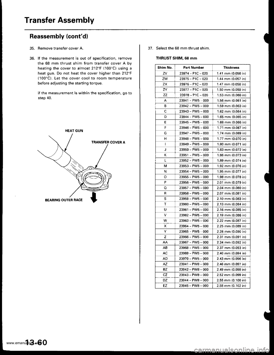
lf the measurement is out of specification, remove
the 68 mm thrust shim from transfer cover A by
heating the cover to almost 212'F (100'C) using a
heat gun. Do not heat the cover higher than 212F
(100"C). Let the cover cool to room temperature
before adjusting the starting torque.
lI the measurement is within the specification, go to
step 40.
COVER A
BEARING OUTER RACE
35.
36.
HEAT GUN
13-60
37. Select the 68 mm thrust shim.
THRUST SHIM, 68 mm
Shim No.Part NumberThickne3s
zv23914-P1C-0201.41 mm (0.056 in)
zw23975-P1C-020'1.44 mm 10.057 in)
zx23916 PlC -020'1.47 mm (0.058 in)
ZI23917 -P1C-O201.50 mm (0.059 in)
zz23978-PlC-0201.53 mm (0.060 in)
23941 - PW5 0001.56 mm {0.061 in)
23942-PWs-0001.59 mm (0.063 in)
c23943-PW5-000't.62 mm (0.064 in)
D23944 PW5 - 0001.65 mm (0.065 in)
E23945-PWs-0001.68 mm (0.066 in)
F23946-PW5-0001.71 mm 10.067 in)
G23947-PW5-000'1.74 mm 10.069 in)
23948-PWs-0001.77 mm (0.070 in)
23949-PWs-0001.80 mm (0.071 in)
239s0-PW5-0001.83 mm (0.072 in)
K23951 - PW5 - 0001.86 mm (0.073 in)
L23952-PWs-0001.89 mm {0.074 in)
239s3-PWs-0001.92 mm {0.076 ini
N23954-PW5-0001.95 mm (0.077 in)
o23955-PW5-0001.98 mm (0.078 in)
P23956 - PW5 , 0002.01 mm (0.079 in)
o23957-PWs-0002.04 mm (0.080 in)
R23958-PWs-0002.07 mm (0.081 in)
23959-PW5-0002.10 mm (0.083 in)
T23960-PW5-0002.13 mm (0.084 in)
U23961 - PW5 - 0002.16 mm (0.085 in)
23962-PW5-0002.19 mm (0.086n)
23963-PWs-0002.22 mm (0.087n)
X23964-PWs-0002.25 mm (0.089n)
23965,PWs-0002.28 mm 10.090n)
23966-PW5-0002.31 mm {0.091 in)
23967-PWs-0002.34 mm (0.092 in)
AB23968-PWs-0002.37 mm (0.093 in)
AC23969-PWs-0002.40 mm {0.094 in}
AD23970-PW5-0002.43 mm (0.096 in)
M23941 - PW8 - 0002.46 mm {0.097 'n}
BZ23942-PW8-0002.49 mm (0.098 in)
cz23943-PW8-0002.52 mm {0.099 ini
DZ23944-PW8-0002.55 mm (0.100 in)
EZ23945-PW8-0002.58 mm (0.102 ini
www.emanualpro.com
Page 500 of 1395

38. Install the 68 mm thrust shim using the special
tools.
DRIVER077€ - 001(xno
THRUST S1{IM,68 mmSelective part
BEARING OUTER BACE
ATTACHMENT.62x68mm077a6 - (x)10500
39.After replacing the 68 mm thrust shim, recheck and
make sure the total starting torque is within the
soecification.
40. Coat the new O-rings with MTF, install them on
transfer covers A and B, then install the covers on
the transfer housing.
6x1.0mm12 N.m 11.2 kgf.m,8.7 tbt.ft)TRANSFER COVER B
TRANSFER
O.RINGReplace.
O.BINGReplace.
TRANSFERCOVER A
8 r 1.25 mm2,r N.m (2.4 kgl.m. 17 lbtft)
13-61
www.emanualpro.com
Page 511 of 1395

Transmission Assembly
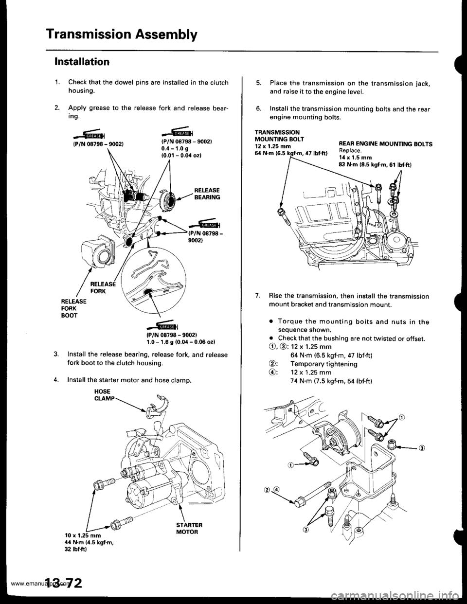
1.
Installation
Check that the dowel pins are installed in the clutch
housing.
Apply grease to the release fork and release bear-
ing.
{P/N 08798 - 90021{P/N 08798 - 9002)0.{ - 1.0 g
{0.0'l - 0.04 ozl
RELEASEBEARING
(P/N 08798 -
9002)
RELEASEFORKBOOT
?
(P/N 08798 - 9002)'1.0 - 1.6 g {0.0,1- 0.06 o2l
Install the release bearing, release fork, and release
fork boot to the clutch housing.
Install the starter motor and hose clamp.
10 x 1.25 mm4{ N'm (4.5 kgf.m,32 tbf.ftl
13-72
HOSE
5. Place the transmission on the transmission jack,
and raise it to the engine level.
6. Install the transmission mounting bolts and the rear
engine mounting bolts.
TRANSMISSIONMOUNTING EOLT12 x 1.25 mn
7.
64 N.m {6.547 tbt.ft)
REAR ENGINE MOUNNNG BOLTSReplace.Itl x 1.5 mm8:l N.m 18.5 kgt m, 61 lbf.ft)
Rise the transmission, then install the transmission
mount bracket and transmission mount.
. Torque the mounting bolts and nuts in thesequence shown.
. Check that the bushing are not twisted or offset.
O. @: 12 x 1.25 mm
64 N.m (6.5 kgf.m, 47 lbf'ft)
O: Temporary tightening
@: 12 x 1.25 mm
74 N.m (7.5 kgf'm,54 lbf.ft)
www.emanualpro.com
Page 515 of 1395

Transmission Assembly
Installation (cont'dl
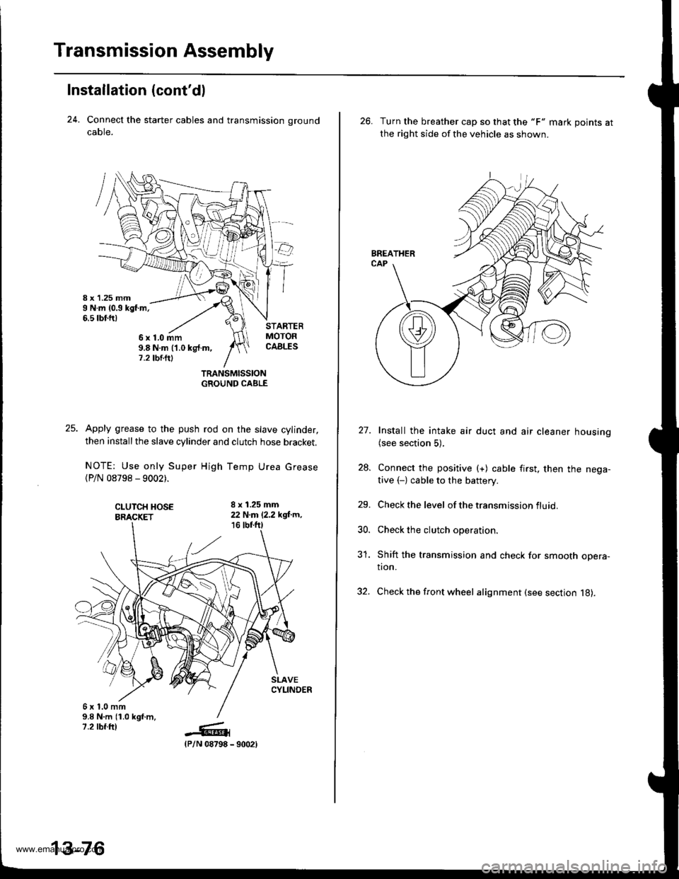
24. Connect the starter cables and transmission ground
caore.
TRANSMISSIONGROUND CABLE
Apply grease to the push rod on the slave cylinder,
then install the slave cylinder and clutch hose bracket,
NOTE: Use only Super High Temp Urea Grease
{P/N 08798 - 9002).
CI-UTCH HOSEBRACKET
8 x 1.25 mm22 N.m 12.2 kgi-m,16 tbr.f0
6x1.0mm9.8 N.m {1.0 kgf.m,7.2 rbf.ftt_G1(P/N 08798
6x1.0mm9.8 N.m (1.0 kg{.m,7.2 tbt.ttl
13-76
- 9002)
26. Turn the breather cap so that the "F" mark points at
the right side of the vehicle as shown.
27. Install the intake air duct and air cleaner housing(see section 5),
28. Connect the positive (+) cable first. then the nega-
tive (-) cable to the battery.
29. Check the level of the transm ission f lu id.
30. Check the clutch operation.
31. Shift the transmission and check for smooth opera-tion.
32. Check the front wheel alignment (see section l8).
www.emanualpro.com
Page 519 of 1395

Description
General Operation
The Automatic transmission is a 3-element torque converter and triple-shaft electronically controlled unit which provides 4
speeds forward and 1 reverse speed The unit is positioned in line with the engine'
There are two tvoes of automatic transmission on CR-V; the four-wheel drive (4WD) model ('97 - 00)' and the front-wheel
drive (2WD) model ('98 - 00).
Toroue Converter, G€ars, and Clutches
The torque converter consists of a pump. turbine. and stator assembly in a single unit. The torque converter is connected to
the engine crankshatt. These parts turn together as a unit as the engine turns. Around the outside of the torque converter is
a ring gear which meshes with the starter pinion when the engine is started. The torque converter assembly serves as a fly-
wheel while transmitting power to the transmission mainshaft.
The transmission has three parallel shafts: the mainshaft. the countershaft, and the sub-shaft. The mainshaft is in line with
the engine crankshaft. The mainshaft includes the 1st, 2nd. and 4th clutches, and gears lor 3rd,2nd,4th. reverse and 1st
(3rd gear is integral with the mainshaft, while reverse gear is integral with the 4th gear). The countershaft includes the 3rd
clutch and gears for 3rd,2nd, 4th, reverse, 1st, and park. Reverse and 4th gears can be locked to the countershaft at its cen-
ter, providing 4th gear or reverse, depending on which way the selector is moved. The sub-shaft includes the lst-hold
clutch and gears for lst and 4th.
The gears on the mainshaft are in constant mesh with those on the countershaft and sub-shaft. When certain combinations
of gears are engaged by the ctutches, power is transmitted from the mainshaft to the countershaft to provide E, D!, tr, tr,
and E position ('97 - 98 models). and E. E, E, and E position ('99 - 00 models)'
Electlonic Control
The electronic controt system consists of the Powenrain Control Module (PCM), sensors, a linear solenoid, and four
solenoid valves. Shifting and lock-up are electronically controlled for comfortable driving under all conditions. The PCM is
located below the dashboard, under the kick panel on the passenger's side.
Hydraulic Control
The valve bodies include the main valve body, the secondary valve body, the regulator valve body, the servo body, and
the lock up valve body. They are bolted to the torque converter housing. The main valve body contains the manual valve,
the 1-2 shift valve, the 2nd orifice control valve. the CPB {Clutch Pressure Back-up) valve, the modulator valve, the servo
control valve. the relief valve, and ATF pump gears. The secondary valve body contains the 2-3 shift valve, the 3-4 shift
valve, the 3,4 orifice control valve. the 4th exhaust valve and the CPC (Clutch Pressure Control) valve. The regulator valve
bodv contains the pressure regulator valve, the torque converter check valve, the cooler relief valve, and the lock-up con-
trol valve. The servo body contains the servo valve which is integrated with the reverse shift tork, and the accumulators
The lock-up valve body contains the lock-up shift valve and the lock-up timing valve. The linear solenoid and the shift con-
trol solenoid valve Ay'B are bolted to the outside of the transmission housing, and the lock-up control solenoid valve Ay'B is
bolted to the outside of the torque converter housing. Fluid trom the regulator passes through the manual valve to the
various control valves. The clutches receive fluid from their respective feed pipes or internal hydraulic circuit
ShiftControl Mechanism
input from various sensors located throughout the vehicle determines which shift control solenoid valve the PCM will acti-
vate. Activating a shift control solenoid valve changes modulator pressure, causing a shift valve to move. This pressurizes
a line to one of the clutches. engaging that clutch and its corresponding gear. The shift control solenoid valves A and B are
controlled by the PCM.
Lock-up Mechanism
tn E! position (,97 - 98 modets) and in E position ('99 - O0 models), in 3rd and 4th, and in Del position in 3rd ('97 - 98
models) and in El position with Over,Drive (O/D) is OFF (by pressing rhe O/D switchl in 3rd ('99 - 00 models), pressurized
fluid is drained from the back of the torque converter through a fluid passage, causing the lock-up piston to be held
against the torque converter cover, As this takes place, the mainshaft rotates at the same speed as the engine crankshaft.
Together with hydraulic control, the PcM optimizes the timing of the lock-up mechanism The lock-up valves control the
range of lock-up according to lock-up control solenoid valves A and B, and the linear solenoid. When lock-up control
solenoid valves A and B activate, the modulator pressure changes. The lock-up control solenoid valves A and B and the
linear solenoid are controlled by the PCM.
{cont'd)
14-3
www.emanualpro.com