Page 240 of 1395
System Description
System Gonnectors [Engine Compartment] -'97 Model {cont'd)
MAIN WIREHARNESS
ENGINEWIBEHARNESS
www.emanualpro.com
Page 246 of 1395
S)stern Dessr\ptron
ENGINEWIREHARNESS
c1z2
(PCM.AI
System Connectors lDash and Floor] -'97 Model {cont'd)
MAIN WIREHARNESS
//l
tao,
{PCM.D}
11-44
www.emanualpro.com
Page 248 of 1395
System Description
System Connectors lEngine Gompartment] -'98 Model
MAIN WIREHARNESS
UNDER.HOODFUSE/RELAYBOX
ENGINEw|REHARNESS
*2: USA
11-46
www.emanualpro.com
Page 250 of 1395
System Description
System Connectors lEngine Compartmentl -'98 Model (cont'd)
MAIN WIRE
ENGINEWIREHARNESS
www.emanualpro.com
Page 252 of 1395
System Description
System Gonnectors lEngine Compartment] -'99 - 00 Models
MAIN WIREHAENESS
UNDER.HOOOFUSE/RELAYBOX
ENGINEWIREHARNESS
www.emanualpro.com
Page 254 of 1395
System Description
System Gonnectors [Engine Compartment] -'99 - 00 Models {cont'dl
MAIN WIREHARNESS
11-52
www.emanualpro.com
Page 260 of 1395
System Description
ENGINEWIREHARNESS
System Conneetors lDash and Floorl -'98 - 00 Models (cont'dl
DASHBOARDWIRE HARNESSMAIN WIB€HARNESS
c,47(ECM/PCM.A}
c121(ECM/PCM-8)
n
lno,
(PCM.D}
www.emanualpro.com
Page 262 of 1395

Troubleshooting
Troubleshooting Procedures
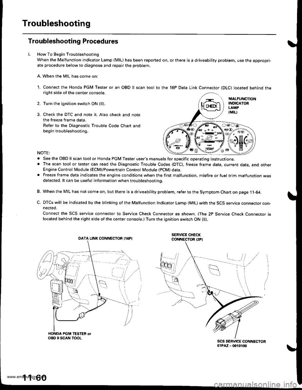
How To Begin Troubleshooting
When the Malfunction indicator Lamp (MlLl has been reported on, or there is a driveability problem, use the appropri-ate procedure below to diagnose and repair the problem.
A. When the MIL has come on:
1. Connect the Honda PGM Tester or an OBD Il scan tool to the 16P Data Link Connector (DLC) located behind theright side of the center console.
Turn the ignition switch ON (ll).
Check the DTC and note it. Also check and note
the freeze frame data.
Refer to the Diagnostic Trouble Code Chart and
begin troubleshooting.
NOTE:
. SeetheOBDll scan tool or Honda PGM Tester user's manuals for specific operating instructions.. The scan tool or tester can read the Diagnostic Trouble Codes (DTC), freeze frame data, current data, and otherEngine Control Module (ECM}/Powertrain Control Module (PCM) data.. Freeze frame data indicates the engine conditions when the first malfunction, misfire or fuel trim malfunction wasdetected. lt can be useful information when troubleshootino.
B. When the MIL has not come on, but there is a driveability problem, refer to the Symptom Chart on page 11-64.
C. DTCs will be indicated by the blinking of the Malfunction Indicator Lamp {MlL) with the SCS service connector con-nected.
Connect the SCS service connector to Service Check Connector as shown. {The 2P Service Check Connecror rslocated behind the right side of the center console.) Turn the ignition switch ON 0l).
DATA LINK CONNECTOR I16PI
1 1-60
www.emanualpro.com