2000 HONDA CIVIC windshield fluid
[x] Cancel search: windshield fluidPage 1347 of 2189
Wiper Arms/Washer Nozzles
Adjustment
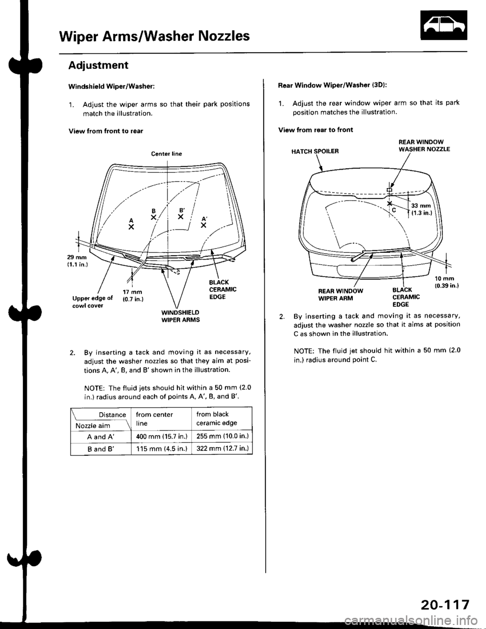
Windshield wiper/Washer:
1. Adjust the wiper arms so that their park positions
match the illustration.
View trom tront to rear
WINDSHIELDWIPER ARMS
2. By inserting a tack and moving it as necessary,
adjust the washer nozzles so that they aim at posi-
tions A, A', B, and B'shown in the illustration.
NOTE: The fiuid jets should hit within a 50 mm (2 0
in.) radius around each of points A, A', B, and B'.
.// \
A'x..
-.4
,'lxiAx
Distance
M;r.";-lll
from center
lrne
from black
ceramrc eoge
A and A'400 mm (15.7 in.)255 mm (10.0 in.)
B and B'115 mm (4.5 in.)322 mm \12.7 in.)
Rear Window wiper/Washer (3Dl:
1. Adjust the rear window wiper arm so that its park
position matches the illustration.
View trom raar to front
CERAMICEDGE
By inserting a tack and moving it as necessary,
adjust the washer nozzle so that it aims at position
C as shown in the illustration.
NOTE: The fluid jet should hit within a 50 mm (2.0
in,) radius around point C.
REAR WINOOWWIPER ARM
r-
---..J_.__11,:l
20-117
Page 1684 of 2189
Wipers/Washers
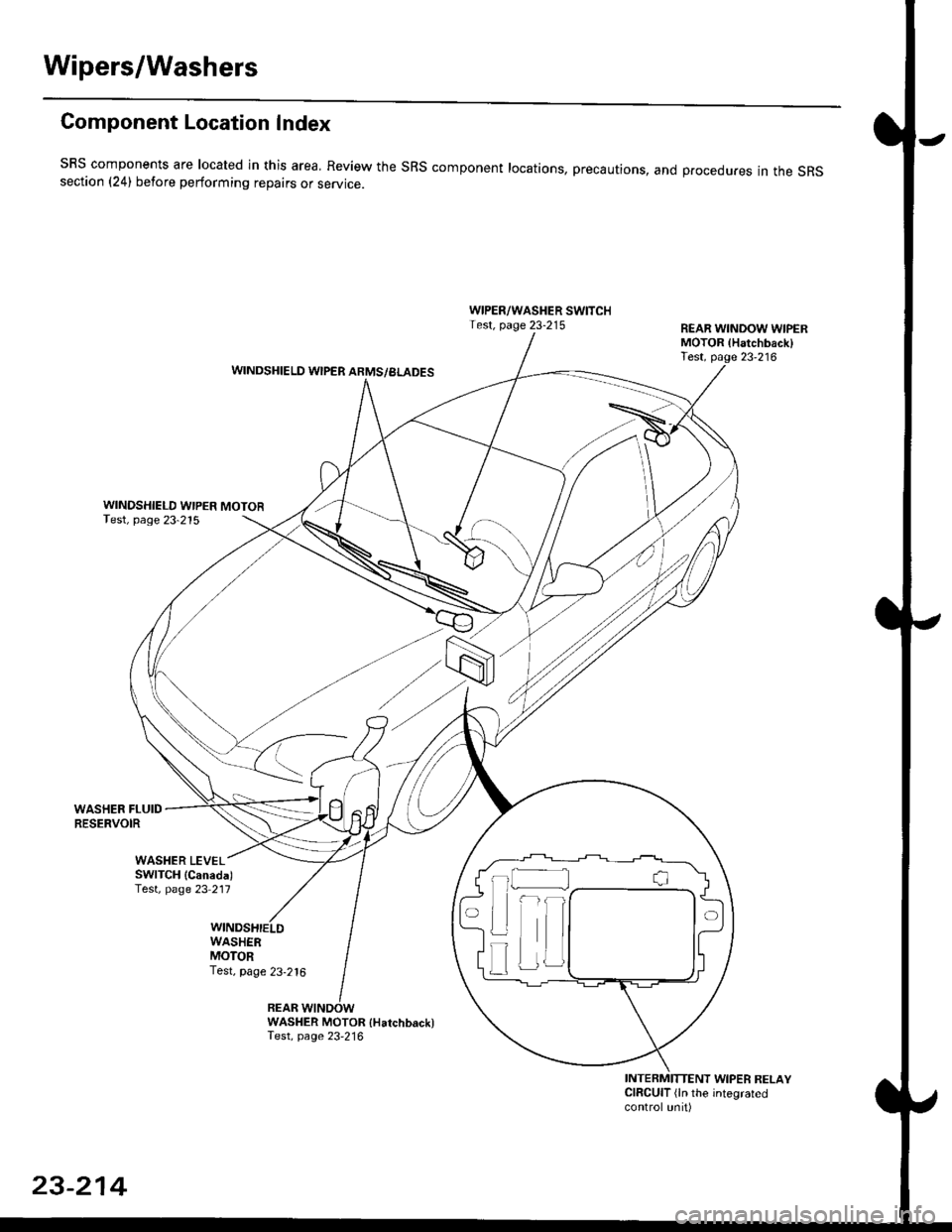
Component Location Index
SBS components are located in this area, Review the SRS component locations, precautions, and procedures in the SRSsection (241 betore performing repairs or service.
WIPER/WASHER SWITCHTest, page 23-215REAR WINDOW WIPERMOTOR lHatchback)Test, page 23'216WINDSHIELD WIPER ARMS/BLADES
WINDSHIELD WIPER MOTORTest, page 23-215
WASHER FLUIDRESERVOIR
WASHER MOTOR {Hatchback)Test, page 23'216
INTERMITTENT WIPER RELAYCIRCUIT (ln the integratedcontrol unit)
t_l
Iilr
i
T
23-214
Page 1840 of 2189
Ground-to-Components I ndex
f.,lONOTE: All ground wires are BLK unless otherwise noted.
GroundPageComponents or Circuit Grounded
Battery (BLKYEL)
Steering pump bracket
t+-rg ITransmission housing
l
G101
(-1)
G101
(-2)
14-2
and
14-3
ano
14-1
Powertrain or engine control module (PG1 and pG2 are BLK: LG1 and LG2 are
BRN/BLK), EGR control solenoid valve (CW, EGR valve and lift sensor (Dt6yS enginewith M,/T), Engine coolant temperature switch, pGM-Fl main relay, power steeringpressure switch (USA), Primary HO2S (D16Y5 engine with l\/,/T), Vehicle speed sensor,VTEC pressure switch (D16Y5/D16Y8 engines), CKF sensor (BRN/BLK), Transmission
control module (CYf) (Pc1 is BLK: LG1 is BRN/BLK)
Shielding betvveen the PCM or ECM and these components (all have BRN/BLK wires):
CKF sensor, TDC/CKP/CYP sensor. Primary and secondary heated oxygen sensors.
Knock sensor (CWDl6YB engine), Mainshaft speed sensor (AiT except CVT),
I Countershaft speed sensor (A/T except CVf)
Shielding between the TCM and these components (CVT) (all have BRN/BLK wires):
Drive pulley speed sensor, Driven pulley speed sensor, Secondary gear shaft
speed sensor
Powertrain or engine control module (PG1 and pG2 are BLK; LG1 and LGz are
BRN/BLK), EGR control solenoid valve (D16Y5 engine), EGR valve (Dt685), Engine
coolant temperature switch, Fuel pressure regulator shut-off solenoid valve (D1685),
PGM-FI main relay, Power steering pressure switch (USA), Vehicle speed sensor, VTECpressure switch (All except D16Y7 engine), CKF sensor (A
except 81642) (BRN/BLK)
Shielding between the PCM or ECM and these components (all have BRN/BLK wires):
CKF sensor, TDC/CKP/CYP sensor, Primary and secondary heated oxygen sensors,
Knock sensor (All except D16Y7 engine), i/ainshaft speed sensor (Arf except CW),
Countershaft speed sensor (A,/T except CVf), Drive pulley speed sensor (CW), Drivenpulley speed sensor (CVT), Secondary gear shaft speed sensor (CVf)
I Badiator fan motor, Right front parking/turn signat tight, Right headtight
G20214-4I Cruise control actuator, Left front parking/turn signal lights, Left headlight, Rear window
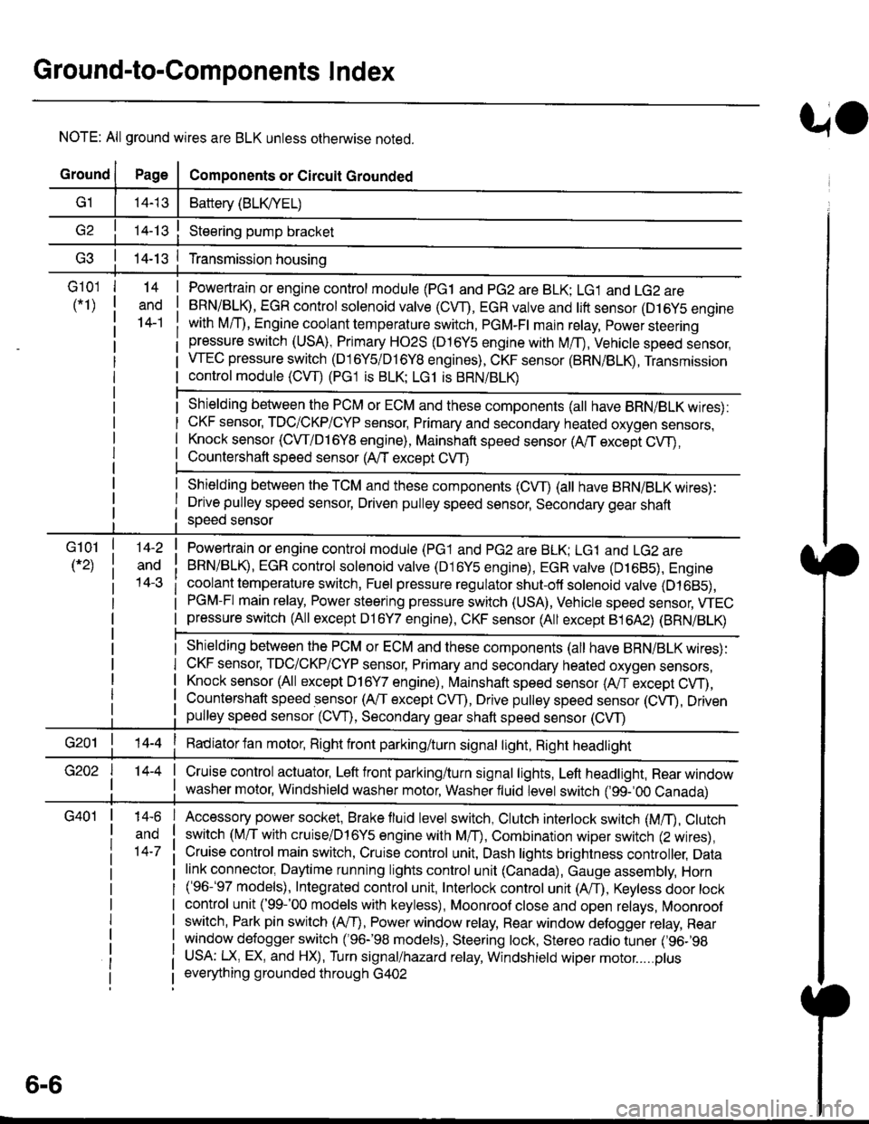
I washer motor, Windshield washer motor, Washer fluid level switch (,99-'00 Canada)
G401| +-o
and
14-7
Accessory power socket, Brake fluid level switch, Clutch interlock switch (M/T), Clutchswitch (lillT with cruise/D16Y5 engine with MfD, Combination wiper switch (Z wires),
Cruise control main switch, Cruise control unit, Dash lights brightness controller, Data
link connector, Daytime running lights control unit (Canada), Gauge assembly, Horn('96-'97 models), Integrated control unit, Interlock control unit (ArI), Keyless door lock
control unit ('99-'00 models with keyless), Moonroof close and open relays, Moonroof
switch, Park pin switch (A/r), Power window relay, Rear window defogger relay, Rear
window defogger switch ('96-'98 models), Steering lock, Stereo radio tuner (,96-,98
USA: LX, EX, and HX), Turn signal/hazard relay, Windshield wiper motor.....plus
everything grounded through G402
6-6
Page 1986 of 2189
Front WiperMasher (cont'd)
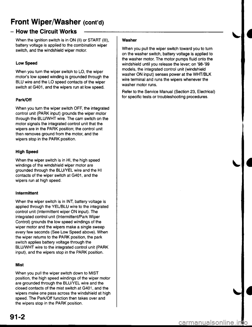
- How the Circuit Works
When the ignition switch is in ON (ll) or START (lll),
battery voltage is applied to lhe combination wiper
switch. and the windshield wiDer motor.
Low Speed
When you turn the wiper switch to LO, the wiper
motor's low speed winding is grounded through the
BLU wire and the LO speed contacts of the wip€r
switch at G401, and the wipers run at low speed.
ParUOfl
When you turn the wiper switch OFF, the integrated
control unit (PARK input) grounds the wiper motor
through the BLUMHT wire. The cam switch on the
motor signals the integrated control unit that the
wipers are in the PARK position; the control unit
then removes ground from the motor, and the
wipers stop in the PARK position.
High Speed
When the wiper switch is in Hl, the high speed
windings of the windshield wiper motor are
grounded through the BLUIrEL wire and the Hl
contacts of the wiper switch at G401, and the
wipers run at high speed.
Intermittent
When the wiper switch is in lNT, battery voltage is
applied through the YEUBLU wire to the integrated
control unit (lntermittent wiper ON input). The
integrated control unit (lnt€rmittenvPark Wiper
Control) grounds the low speed windings of the
wiper motor and the wipers make a single sweep
every few seconds (See Low Speed above). When
the wiper retums to the PARK position, the park
switch applies battery voltage through the
BLUMHT wire to the integrated control unit (PARK
input), and the wipers stop in the PARK position.
Mist
When you pull the wiper switch down to MIST
position, the high speed windings ot the wiper motor
are grounded through the BLU^/EL wire and the
closed contacts ot the mist switch at G401, and the
wipers make one pass across the windshield at high
speed. The ParUOff function then takes over and
the wipers stop in the PARK position.
Washel
When you pull the wiper switch toward you to turn
on the washer switch, battery vollage is applied to
the washer motor. The motor pumps fluid onto the
windshield until you release the lever; on '98r99
models, the integrated control unit (windshield
washer ON input) s€nses power at the WHT/BLK
wire terminal and runs the wipers whenever the
washer motor runs.
Refer lo the Service Manual (Seclion 23, Electrical)
for specific tests or troubleshooting procedures.
91-2
Page 2159 of 2189
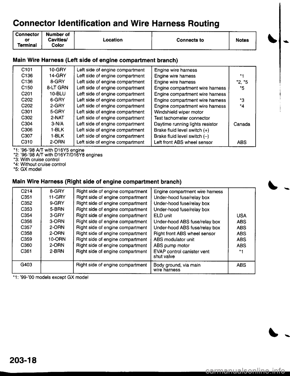
Connector ldentification and Wire Harness Routino
Connector
or
Terminal
Number ot
Cavities/
Color
LocationConnects toNotes
Main Wire Harness (Left side of engine compartment branch)
c101
cI36
c136
c150
c201
c202
c202
c301
c302
c304
UOUO
c307
c310
1O.GRY
14-GRY
8.GRY
8.LT GRN
1O-BLU
6.GRY
2-GRY
5.GRY
2.NAT
3-N/A
1.BLK
1-BLK
2.ORN
Left side ot engine compartment
Left side of engine compartment
Letl side of engine compartment
Lett side of engine compaftment
Left side of engine compartment
Left side of engine compartment
Left side of engine compartment
Left side of engine compartment
Left side of engine compartment
Left side of engine compartment
Left side of engine compartment
Left side of engine compartment
Left side of engine compartment
Engine wire harness
Engine wire hamess
Engine wire hamess
Engine compartment wire harness
Engine compartment wire harness
Engine compartment wire harness
Engine compartment wire harness
Windshield wiper motor
Test tachomeier connector
Daytime running lights resistor
Brake fluid level switch (+)
Brake fluid level switch (-)
Left front ABS wheel sensor
.1
'r.q
r5
.4
Canada
ABS
.1 : '96-98 A/T with D16Y5 enoine'2: '96-98 A,/T with D16Y7/D16Y8 enoines.3: With cruise control*4: Without cruise control.5: GX model
Main Wire Harness (Right side of engine compartment branch)
c214
c351
wacl
UJCJ
c356
c357
c358
UOCY
c360
c361
8-GRY
11.GRY
9.GRY
5-BRN
3-GRY
3-ORN
2.ORN
2-ORN
10-oRN
2.ORN
2-8RN
Right side of engine compartment
Right side of engine compartment
Right side of engine compartment
Right side of engine compartment
Right side of engine compartment
Right side of engine comparlment
Right side ot engine compartment
Right side ot engine companment
Right side of engine compartment
Right side of engine compartment
Right side of engine compartment
Engine compartment wire hamess
Under-hood fuse/relay box
Undef-hood tuse/relay box
Under-hood fuse/relay box
ELD unit
Under-hood ABS fuse/relay box
Underhood ABS fuse/relay box
Right front ABS wheel sensor
ABS modulator unit
ABS pump motor
EVAP control canister vent
shut valve
USA
ABS
ABS
Al'D
AE5
ABS-1
G403Bight side of engine compartmentBody ground, via mainwtre narnessABS
.1: '99-'00 models except GX model
203-18