Page 158 of 2189
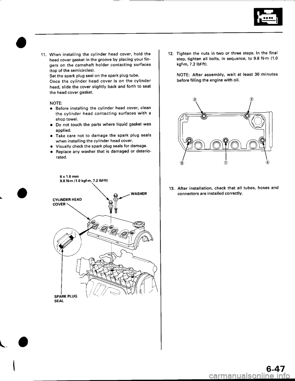
11. When installing the cylinder head cover, hold the
head cover gasket in the groove by placing your fin-
gers on the camshaft holder contacting surfaces
(top of the semicircles)
Set the spark plug seal on the spark plug tube.
Once the cylinder head cover is on the cylinder
head, slide the cover slightly back and forth to seat
the head cover gasket.
NOTE:
. Before installing the cylinder head cover, clean
the cylinder head contacting surfaces with a
shop towel.
. Do not touch the parts where liquid gasket was
aDolied.
. Take care not to damage the spark plug seals
when installing the cylinder head cover,
. Visually check the spark plug seals for damage.
. Replace any washer that is damaged or deterio-
rated.
6x1.0mm9.8 N.m 11.0 ksf.m,7.2lbf ftl
\g-----*o""t'Ptl
veEE
\_
6-47
12. Tighten the nuts in two or thre€ steps. In the final
step, tighten all bolts, in sequence, to 9 8 N'm (1.0
kgf.m, 7.2 lbf.ft).
NOTE: After assemblv, wait at least 30 minutes
before filling the engine with oil
After installation, check that all tubes, hosss and
connectors are installed correctlY
1?
Page 197 of 2189
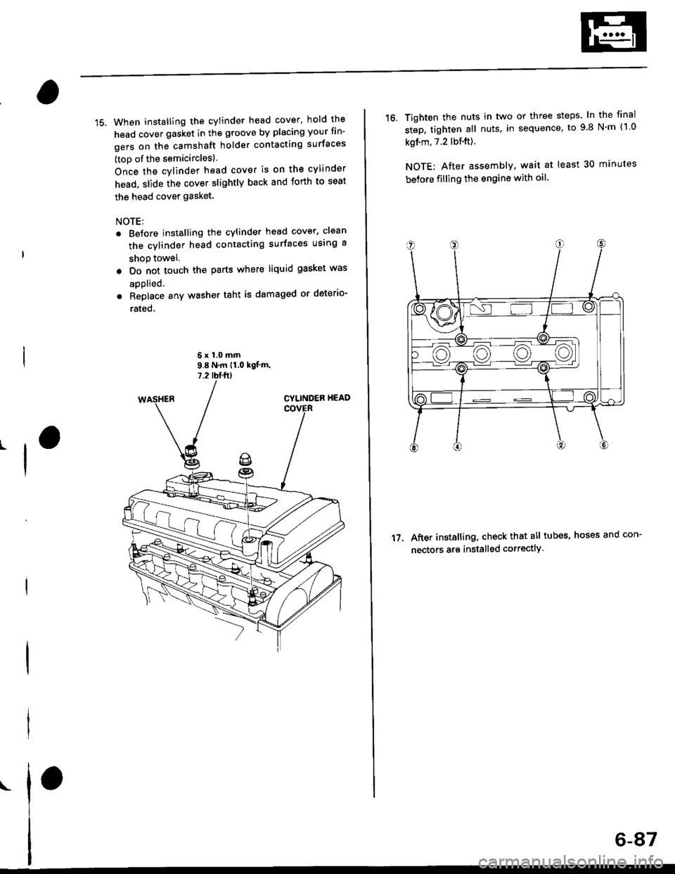
15. When installing the cylinder head cover, hold the
head cover gasket in the groove by placing your fin-
gers on the camshaft holder contacting surfaces
(toD of the semicircles).
Once the cylinder head cover is on the cylinder
head, slide the cover slightly back and forth to seat
the head cover gasket.
NOTE:
. Be{ore installing the cylinder head cover, clean
the cvlinder head contacting surfaces using a
shoP towel.
. Oo not touch the parts where liquid gasket was
applied.
. Replace any washer taht is damaged or deter'o-
rated.
t
\
6-A7
16. Tighten the nuts in two or three steps. In the final
step, tighten all nuts, in sequence, to 9 8 N'm {1 0
kgf.m, 7.2 lbf.ft).
NOTE: After assembly, wait at least 30 minutes
before filling the engine with oil.
After installing, check that all tubes' hoses and con-
nectors are installed correctly.17.
Page 1105 of 2189
)
Disassembly
t)
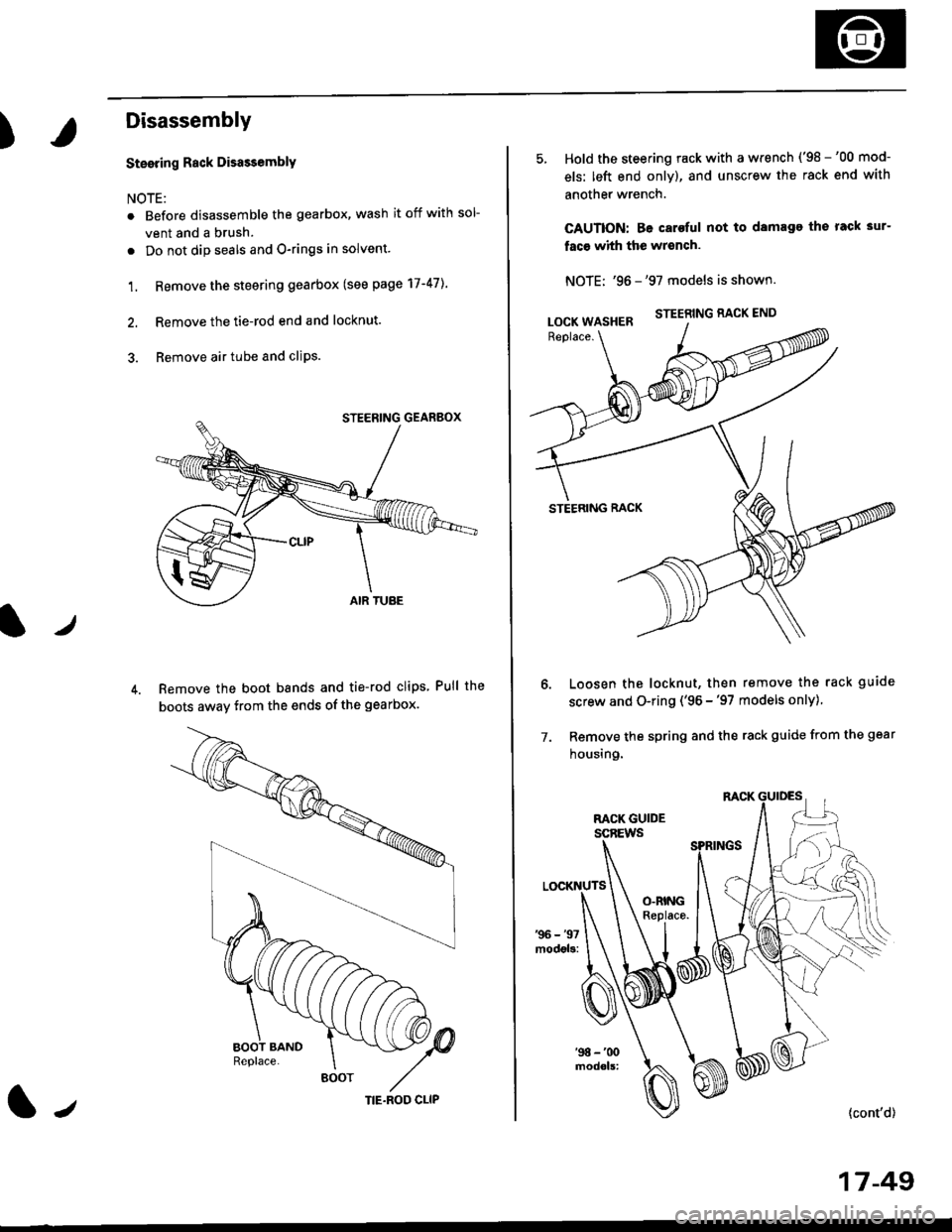
Steering Rack DisassemblY
NOTE:
r Before disassemble the gearbox, wash it off with sol
vent and a brush.
. Do not dip seals and O-rings in solvent.
1. Remove the steering gearbox (see page 17-47]..
2. Remove the tie-rod end and locknut.
3. Remove air tube and cliPs.
Remove the boot bands and tie-rod clips Pull the
boots away from the ends of the gearbox.
BOOT
(|-,TIE.ROD CLIP
Hold the steering rack with a wrench ('98 -'00 mod-
els: left end only), and unscrew the rack end with
another wrench.
CAUTION: Be caroful not to damage the rack 3ur-
faco whh the wrench.
NOTE: '96 -'97 models is shown.
STEERING RACK END
STEERING RACK
Loosen the locknut, then remove the rack guide
screw and O-ring ('96 -'97 models only)
Remove the spring and the rack guide from the gear
housing.
7.
{cont'd}
17 -49
LOCK WASHER
Page 1331 of 2189
Hatch Spoiler
Removal
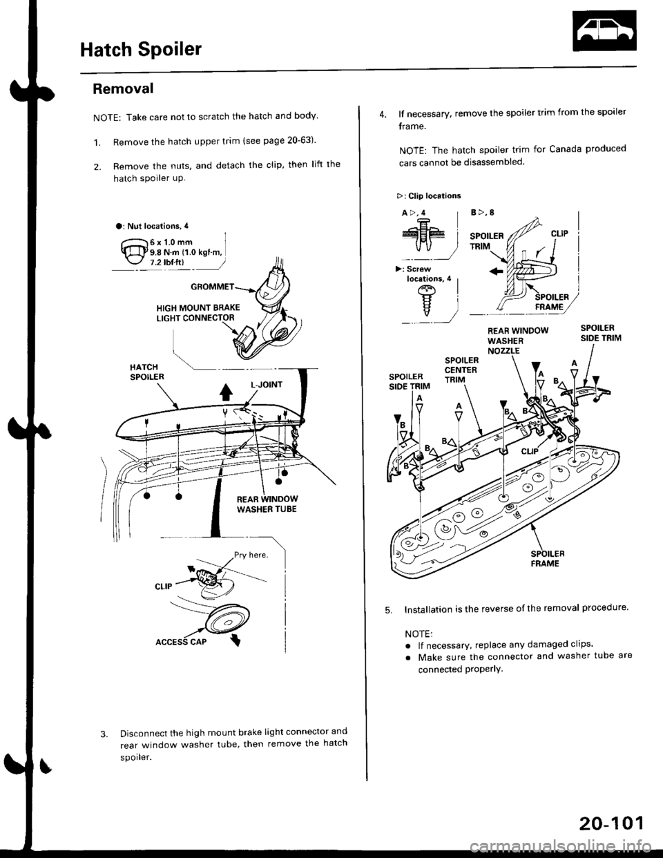
NOTE: Take care not to scratch the hatch and body
1. Remove the hatch upper trim (see page 20-63)
2. Remove the nuts, and detach the clip, then lift the
hatch spoiler uP.
a: Nut locations, 4
1 2lbt.ftl _ j/
GROMMET
HIGH MOUNT BRAKELIGHT CONNECTOR
Disconnect the high mount brake light connector and
rear window washer tube, then remove the hatch
spoiler.
------,*;)
4. lf necessary. remove the spoiler trim from the spoiler
frame.
NOTE: The hatch spoiler trim for Canada produced
cars cannot be disassembled.
>: Clip locations
A>,4
>: Scr€w
5. Installation is the reverse of the removal procedure'
NOTEi
. lf necessary, replace any damaged clips.
a Make sure the connector and washer tube are
connected ProPerlY.
20-101
Page 1337 of 2189
Opener Cable/Opener and Latch/Wiper and Washer
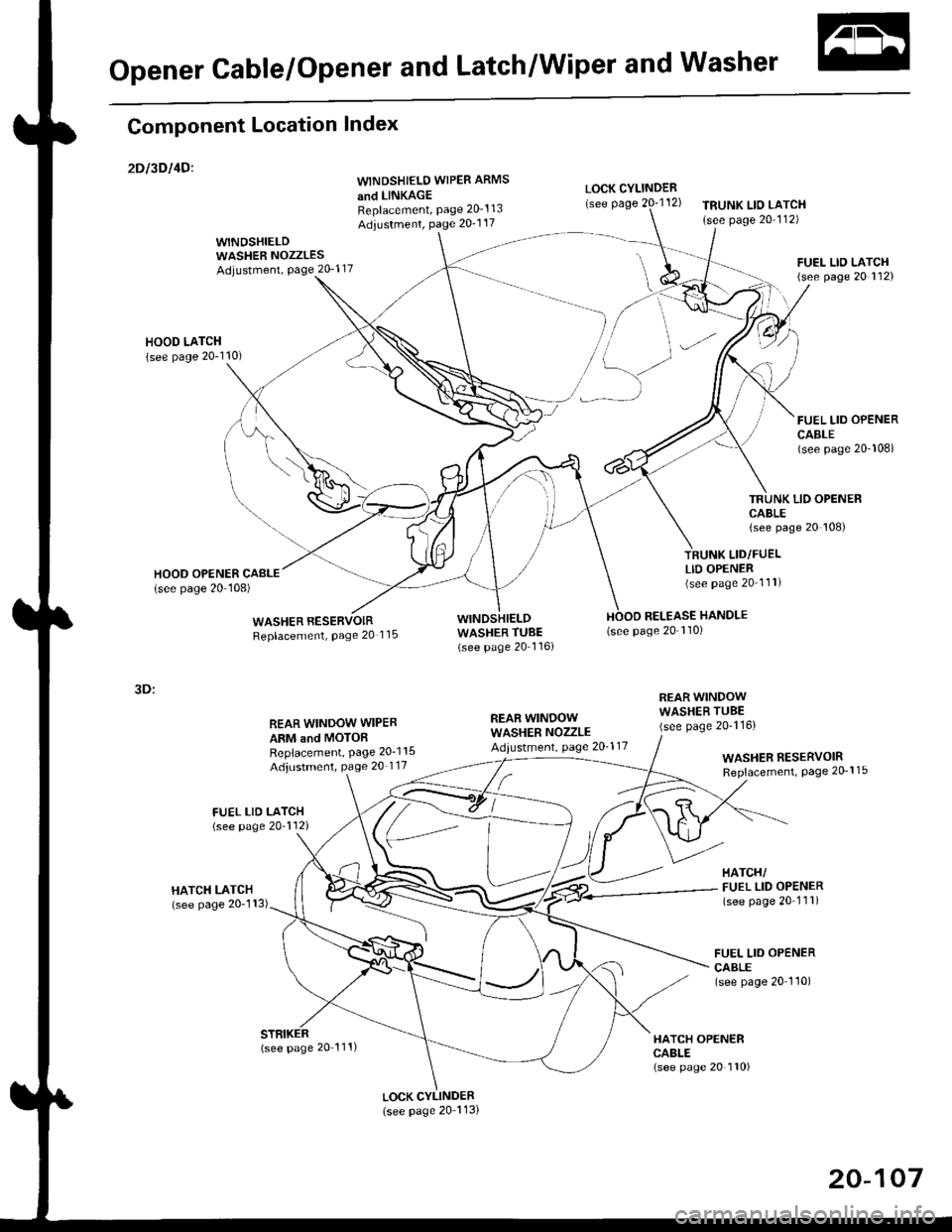
Component Location Index
2Dt3DItD'
y"Tl,"nll,ib?*'r.* o*t"
Replacement, Page 20_1 13
Adiustment, Page 20'1 17
WINDSHIELDWASHER NOZZLESAdjustment, Page 20_1 17
HOOD LATCH
{see page 20-110)
REAR WINDOW WIPER
ARM and MOTORReplacement, Page 20-1 15
Adjustment, page 20 117
LOCK CYLINDER(see page 20 113)
LOCK CYLINDER
TRUNK LIO LATCH
{see page 20 112)
FUEL LID OPENERCABLE(see page 20-108i
LID OPENERCABLE(see page 20 108)
LID/FUELLID OPENER(see page 20 111)
RELEASE HANDLE(see page 20-110)
3D:
REAR WINDOWWASHER NOZZLEAdiustment, page 20-1 17
REAR WINDOWWASHER TUBE(see page 20-116)
HATCH OPENERCABLE(see page 20 110)
WASHER RESERVOIRReplacement, Page 20-1 15
HATCH/FUEL LID OPENER(see page 20 1'11)
FUEL LID OPENERCABLE(see page 20 110)
(see page 20 111)
20-107
Page 1345 of 2189
Rear Window Wiper
Arm and MotorWasher Reservoir
Replacement
't.
2.
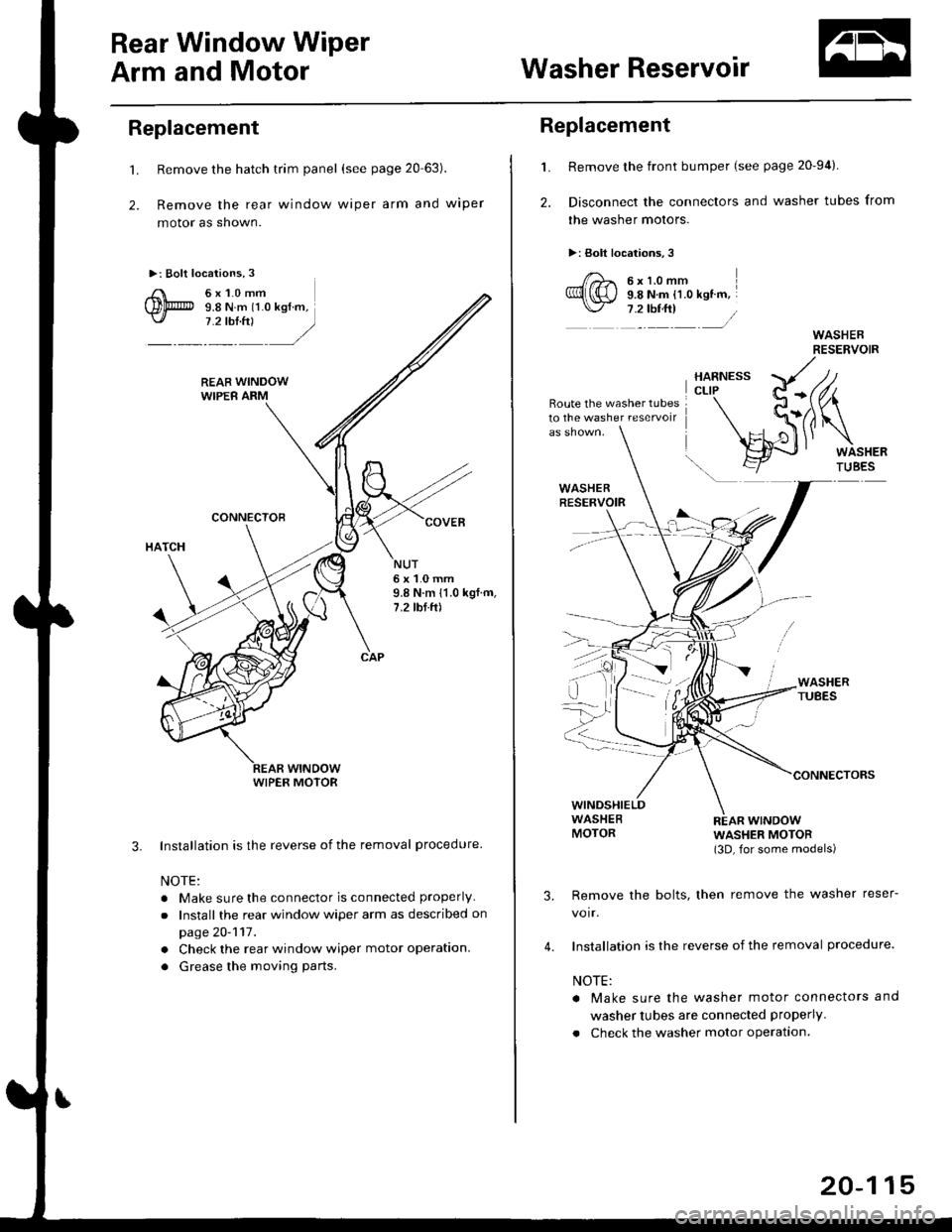
Remove the hatch trim panel (see page 20 63).
Remove the rear window wiper arm and wiper
motor as shown.
Installation is the reverse of the removal procedure
NOTE:
. Make sure the connector is connected properly
.Install the rear window wiper arm as described on
page 20-117.
. Check the rear window wiper motor operation.
. Grease the moving parts.
3.
NUT6x1.0mm9.8 N.m 11.0 kgf.m,7.2 tbf.ft)
WIPER MOTOR
L
2.
Replacement
Remove the front bumper (see page 20-94).
Disconnect the connectors and washer tubes from
the washer motors.
>: Bolt locations,3
/)^ 6xt.omm
Ql(S) s.e ru.- tt.o ret '".\./ 7 .2 tbf.ft) /
Route the washer tubes10 the washe. reservoir
wtNDowWASHER MOTOR(3D, for some models)
Remove the bolts, then remove the washer reser-
voir.
Installation is the reverse of the removal procedure.
NOTE:
a Make sure the washer motor connectors and
washer tubes are connected properly.
. Check the washer motor operation.
3.
4.
20-115
Page 1346 of 2189
Washer Tube
Replacement
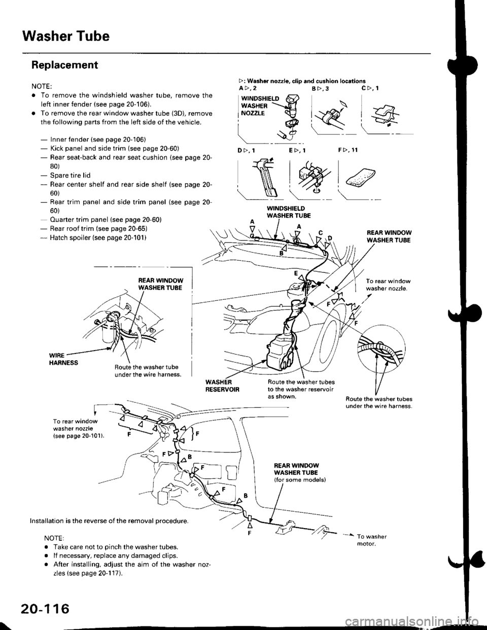
NOTE:
. To remove the windshield washer tube, remove the
left inner fender (see page 20-106),
. To remove the rear window washer tube {3D), remove
the following parts from the left side of the vehicle.
- Inner fender (see page 20-106)- Kick panel and side trim (see page 20-60)- Rear seat-back and rear seat cushion (see page 20-
80)- Spare tire lid- Rear center shelf and rear side shelf (see page 20-
60)- Rear trim panel and side trim panel
60)
Ouarter trim panel (see page 20-60)- Rear roof trim {see page 20-65)- Hatch spoiler (see page 20-101)
(see page 20
WIREHARNESS
>: W.sher nozzle, clip and cushion locationsa>,2B>,3
"J>)
[q@"
F>, 11
c>, 1
wttrtosnteLo 6}usxea =-d
lNozzrE cv
iq
!$e
D>,1 E>, 1
NtW)€
Roote the washer tubeunder the wire harness.
TUBE
A
Route the washer tubesto the washer reservoir
REAB WINDOWWASHER TUBE(Ior some models)
REAR WINDOWWASHER TUBE
washer nozzle.
washer nozzle(see page 20-101).
oo\
Installation is the reverse of the removal procedure.
NOTE:
. Take care not to pinch the washer tubes.
. lf necessary, replace any damaged clips.
. After installing, adjust the aim of the washer noz-
zles (see page 20-117).
20-116
WINDSHIELD
\,--
Page 1352 of 2189
Body ('97 model)
Front Seat Belt
Removal/lnstallatlon ....20-128
Rear Seat
RemovaUlnstallation ....20-126
Washer Tube
Windshield
fndex .......... 20-124
Outline of '97 Model Changes
The molding side seal was added.
The method of installing the rear seat cushion was changed (2Dl3D).
A middle floor gusset was added and the method of detaching the seat belt retractor was changed (2Dl3D)
The installation position of the washer tube was changed.