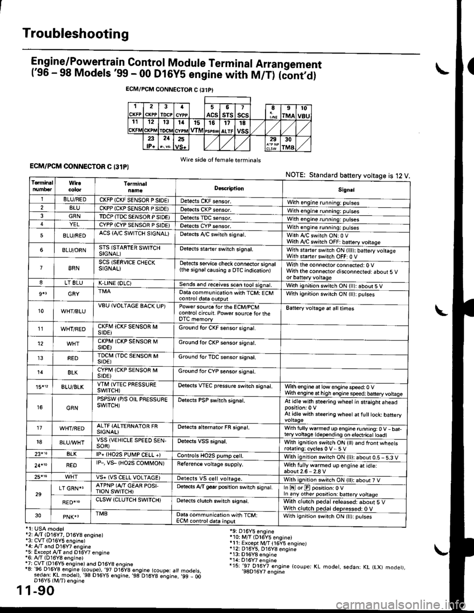
2000 HONDA CIVIC DLC terminal
[x] Cancel search: DLC terminalPage 359 of 2189
Troubleshooting
Engine/P_o_wgrtrain Control Module Terminal Arrangement('96 - 98 Models '99 - 00 Dt6y5 engine with M/T) tc'oniOi
ECM/PCM CONNECTOR C {31PI
1
CKFP
2
CXPPTDCPa
ACS
5
sTs
7
scsII
rMA
10
v8u121314t51517
ALTF
TE
vss23lP+
21252930
TMA
Wire side of female terminalsECM/PCM CONNECTOR C (31PI
NOTE: Standard baftery voltage is 12 V
'1: USA modelr2rA,.T (D16Y7, O16Y8 ensane)*3: CVT (O16Y5 engine)*4: Ay'T and O16Y7 engine'5: Excepl A./T snd Dl6Y7 engine16: Ay'T (D16Y8 ensine){7: CVT (Dl6Y5 eosine) and O16Y8 enoine"8: 96 Dl6Y8 engine (coupe),'97 D16y8 engine (coupe: atl:ed-9I t!!rnodelr,'98 D16y5 ensine,,98 D16y8 e;sine.D16Y5 lM/T) ensine
1-90
19: D16Y5 engine'10: M/T (Dl6Y5 engine)*11r Except M/T 116Y5 engine)*12: D16Y5, D16Y8 engine*13: Dl6Y8 enqine*14: O16Y7 enginei15: '-97 O16Y7 engjne (coupe: KL modet, sedan: KL (LX) modet),'98D16Y7 enqine'99 - 00
1
To.min!lnumberWiracoloaTorminalnameDo6criptlonSignal
1BLU/REDCKFP (CKF SENSOR P SIDE)Detects CKF sensor.With engine running: pulses2BLUCKPP (CKP SENSOF PSIDE)Detects CKP sensor.With engine running: pulses3GRNTDCP {TDC SENSOR PSIDE}Detects TDC sensor,With engine running: putses4YELCYPP (CYP SENSOR P SIDE)Detects CYP sensor.With engine running: pulses
5BLU/FEDACS {Tr'C SWITCH SIGNAL)Detects ,ay'C sw;tch signat.With Iy'C switch ONr 0 VWith Ay'C switch OFF: batrery vottage
6BLU/ORNSTS (STARTER SWITCHSIGNAL)Detects staner swilch signal,With staner switch ON ltlt): batery vohageWith staner switch OFF: 0 V
8RNSCS (SERVICE CHECKSIGNAL)Detects service check connector signal{the signalcausing a OTC indicationlWith the connector connected: O Vwith the connector disconnected: about 5 vor battery voltageLT 8LUK,LINE (DLC)Sends and receives scan iool signal,Wirh ignition switch ON { ): about 5 V
9+3GRYDat6 communication with TCM: ECMcontrol ctat6 outputWith ignition switch ON (tt):putses
10WHT/BLUVBU (VOLTAGE BACK UP)Power source forthe ECM/PCMcontrol circuit. Power sourc€ lortheDTC memory
Battery voltage at all times
11WHT/REDCKFM {CKF SENSOR MSIDE)Ground tor CKF sensor signal.
12CKPM (CKP SENSOR MSIDE)Ground for CKP sensor s;gnat.
REDTDCI\4 (TDC SENSOR MSIDE)Ground for TDC sensor signal.
14BLKCYPM (CKP SENSOB MSIDE}Groond for CYP sensor signal.
15."BLU/BLKVTM (VTEC PRESSUREswtTcH)Oetscts VTEC pressure switch signal.Wrth engine at low enginespeed:0 VWth engineathigh engine speed: tatteryvoltase
16GRN
PSPSW (P/S OIL PRESSUREswtTcH)Detects PSP switch signal.At idle with steering wheel in straight aheadposition:0 VAt idle with stsering wheet at fult tock batteryvoltage'17WHT/REDALTF (ALTERNATOR FRSIGNAL)Detects ahernator FR signal.With fullyw6rmed up engine running:0 V- bat-teryvohage (depending on electricat toad)18BLUI/VHTVSS {VEHICLE SPEED SEN-SOR}Oetects VSS signal.Whh ignitjon switch ON {tt) and front wheetsrotating: cycles 0 V- 5 V23+14BLKlP+ {HO2S PUtr4P CELL +}Controls HO2S pump ce .With ignition switch ON (ll): abour 0.5 - 5.3 V
24.10REDrP-, vs- {Ho2s coMt oN)Reference voltage supply.With fullywarmed up engine et idle:about2.6-2.8 V25*roVS+ (VS CELL VOLTAGE)Detects VS cell voltage.With ignition switch ON t): abour 7 V
29LT GRN*'ATPNP (Ar'T GEAR POSI,TroN swrTcH)Deteds Ay'T g6srposhion switch signat.In E orE position: O Vln any other position: battery vottage
RED{roCLSW (CLUTCH SWITCH}Detects clutch switch signal,Wilh clutch pedal released: about 5 VWith clutch pedal deDressed: O V30PNK4TMBData communication with TCM:ECM controldata inputWith ignit;on switch ON (lt):putses
Page 726 of 2189
Troubleshootin g Procedures
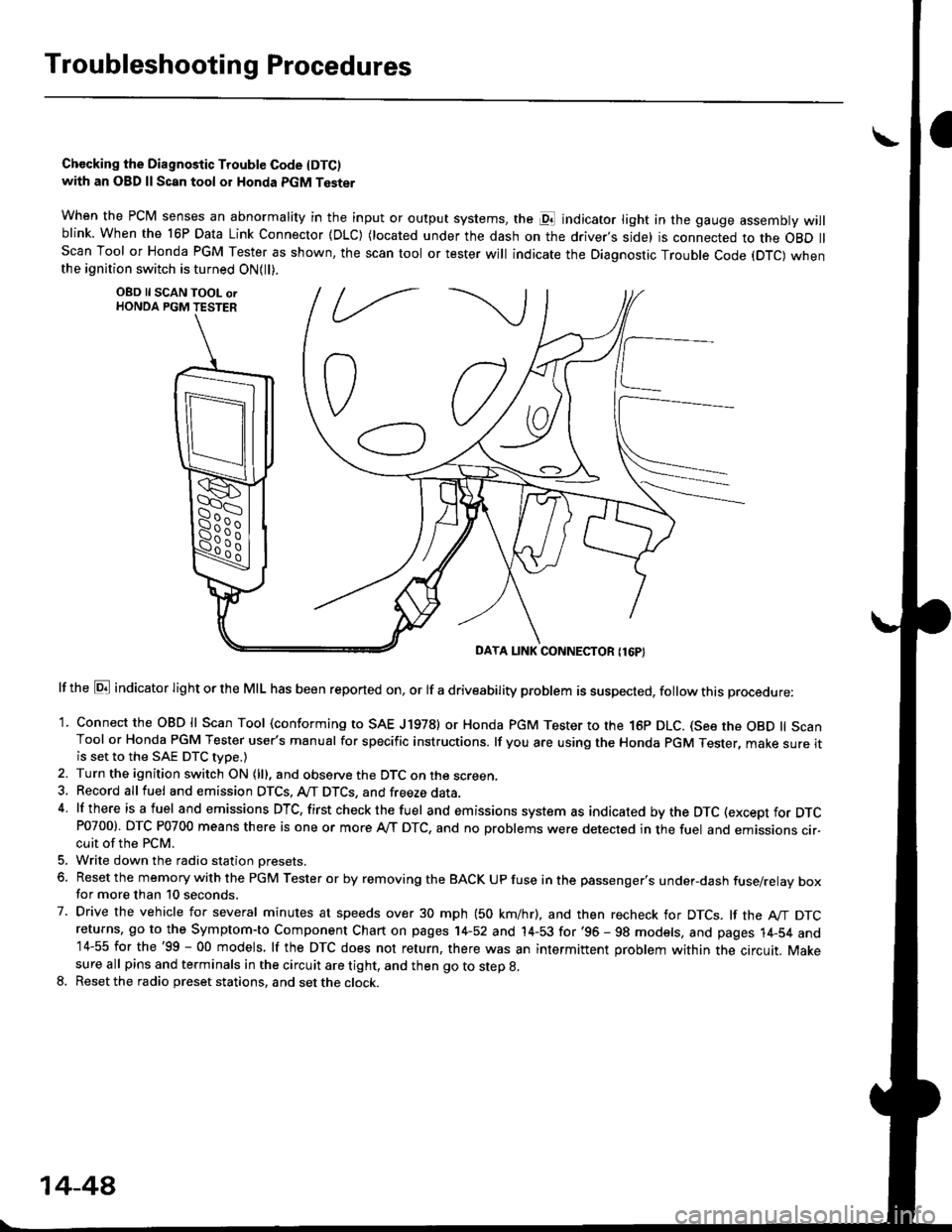
Chccking the Diagnostic Trouble Code IDTC)with an OBD ll Scan tool or Honda PGM Tester
when the PCM senses an abnormality in the input or output systems, the pl indicator light in the gauge assembly willblink. When the 16P Data Link Connector (DLC) (located under the dash on the driver,s side) is connected to the OBD llScan Tool or Honda PGM Tester as shown, the scan tool or tester will indicate the Diagnostic Trouble Code (DTC) whenthe ignition switch is turned ON{ll).
lf the El indicator light or the MIL has been reported on, or lf a driveability problem is suspected, follow this procedure:
1. Connect the OBD ll Scan Tool (conforming to SAE J19781 or Honda PGM Tester to rhe 16p DLC. (See the OBD ll ScanTool or Honda PGM Tester user's manual for specific instructions. lf you are using the Honda PGM Tester, make sure itis set to the SAE DTC type.)
2. Turn the ignition switch ON (lll, and observe the DTC on the screen,3, Record all fuel and emission DTCS, A/T DTCS, and freeze data.4 lf there is a fuel and emissions DTC, first checkthe fuel and emissions system as indicated bythe DTC (except for DTCP0700). DTC P0700 means there is one or more A,/T DTC, and no problems were detected in the fuel and emissions cir-cuit of the PCM.
5. Write down the radio station oresets.
6. Reset the memory with the PGM Tester or by removing the BACK UP fuse in the passenger's under-dash fuse/relay boxfor more than 10 seconds.
7. Drive the vehicle for several minutes at speeds over 30 mph (50 km/hr), and then recheck for DTCS. lf the A"/T DTCreturns, go to the Symptom-to Component Chart on pages 14-52 and 14-53 for'96 - 98 models, and pages 14-54 and14-55 for the'99 - 00 models, lf the DTC does not return, there was an intermittent problem within the circuit. Makesure all pins and terminals in the circuit are tight, and then go to step g.
8. Reset the radio preset stations, and set the clock.
OBD ll SCAN TOOL orHONDA PGM TESTER
DAYA LINK CONNECTOR {16P}
14-44
Page 1206 of 2189
lOutput voltagolTqrminal namslterminils
RED/B")
e\
t
ABS CONTROL UNIT 22P CONNECTOR
Wire side of female terminals
TerminalnumbelWirocororTerminalsignDe3cription
Volt.ge
ConditionE(lgnition Switch ON (ll)lOutput voltagolTqrminal namslterminils
RED/BLUFR-IN{Front-rightinlet)
Drives right-front inletsolenoid valve.
I-GNDriJ
ON-9ONOV
OFFAC: 3-6 V
OFF
/Connect the SCS servicq
connector IApprox. 3 V
BRNscs(Service checksignal)
Detects service check signal
{Diagnostic trouble codeindication)4-GND
SCS service connectorconnected.OV
SCS service connectordisconneded.Appro)(. 5 V
7BLU/RED(Warning
ramp)
Drives ABS indicator light (The
indicator light go€s off when
ABS control unit outputs bat-
tery volta9e),
7-GND
Indicator light ONApprox, 2 V
Indicator light OFFBattery voltage
8BLU/YELNot used.
10YEUBLKFL.OUT{Front-leftoutlet)
Drives left-front outletsolenoid valve.10-GNOON
ONOV
OFFAC:3-6 V
11RED/BLKFLIN{Front-l€ft inlet)
Drives left-front inlet solenoid11-GNDOFF
lconnect the SCS servicq
connector IApprox. 3 V
YEUBLU
FR.OUT(Front-right
outlet)
Drives right-front outlet
solenoid valve.12-GNO
l4LT BLUDLC(Data linkconnector)
Communicates withPGM Tester.Honda14.GNDApprox. 5 V
17BRNA/ELMCK
lMotor check)
Detects pump motor drivesrgnal.17.GNDPumpmotorreray
ONBattery voltage
OFFOV
19YELREDPMR(Pump motorreray,
Drives pump motor relay.
19-GND
ONONOV
OFFAC: 3-6 V
OFFponnect the SCS sewicq
connedor lApprox. 3 V
BLURR-OUT(Rear-right
outletl
Drives right-rear outlel
solenoid valve.
21-GNDuJ
ON
Pumpmotorrelay
ONOV
OFFAC: 3-6 V
OFF
lconnect the SCS servicq
connedor )Approx. 3 V
22BLKGND2(Ground 2)Ground for the ABS controluntt.22-GNDBelow 0.3 v
19-53
Page 1744 of 2189
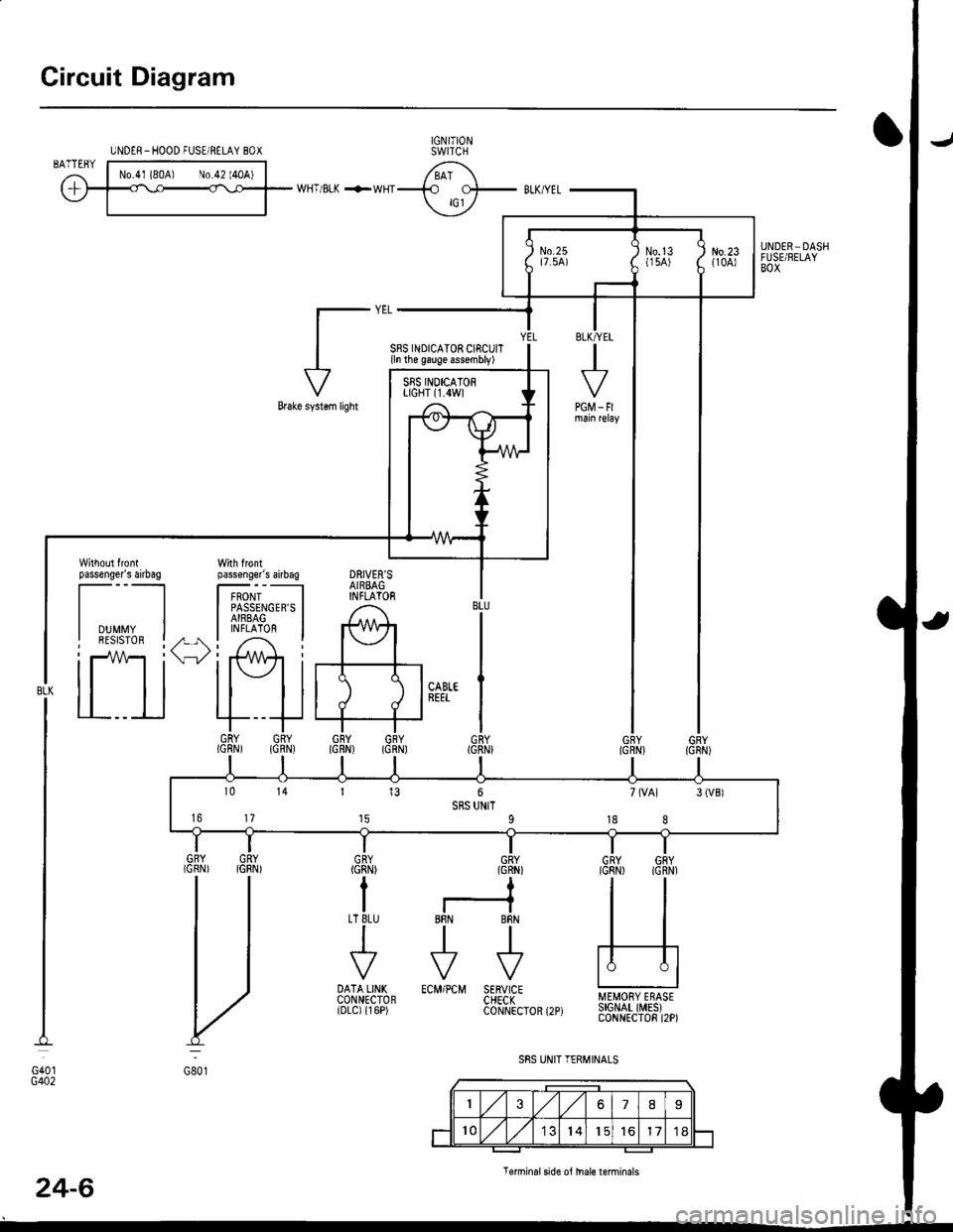
Circuit Diagram
UNDER-HOOD FUSE/RELAY 8OXIGNITIONSWITCH
WHT/8LI( +WHT
Brake systsm light
passenger's airbag
l----ltlI DUMMY II BESISTOR I
tll
tl
la rl
MEMORY ERASESIGNAT IMES)CONNECTOR I2P)
GRY{GRN)
I
BRN BRN
tl.-l- .-r-\./ \./
ECM/PCM SERVICECHECKCONNECTOR
ILT 8LU
I
t'7
DATA LINKCONNECTOR{DLC) {r6P)
GRY GRY(GRN) IGNN)
V:
G801
Teminalside oi thal€ terminals
24-6
4''
SRS UNIT TERMINALSG40tG402
SBS INDICATOR CIRCUIT{ln the gauge assembly)
PGM_FI
DRIVER'SAIRBAGINFLATOR
10 14 r 13 6 7(VAl 3{VBlSRS UNIT16 17 t5 9 18 8
Page 1751 of 2189
rl
Troubleshooting
t)
Self-diagnostic Procedures
The self-diagnostic function of the SRS system allows it to locate the causes of system problems and to store this informa' I
tion in memory. For easier troubleshooting, this data can be retrieved via a data link circuit l
. When you turn the ignition switch ON (ll), the SRS indicator will come on. ll it goes off after six seconds. the system is
norma l.
. lf there is an abnormality, the system locates and defines the problem, stores this information in memory, and turns
the sRS indicator light on. The data will remain in the memory even when the ignition switch is turned off or if the bat-
tery is disconnected.
o when you connect the scs service connector to the service check connector (2P), and turn the ignition switch oN (ll),
thesRsindicator|ightwi||indicatethediagnostictroub|ecode(DTC)bythenumberofb|inks.
. After reading and recording the DTC. proceed with the troubleshooting for this code'
Precauiions
.Useon|yadigita|mU|timetertocheckthesystem'|fit,snotaHondamu|timeter,makesureitsoutputisl0mA(0.01A)
or|esswhenSwitchedtothesma||estva|ueintheohmmeterrange,AtesterwithahigheroUtpUtcoulddamagethe
airbag circuit or cause accidental airbag deployment and possible injury'
r when-ever the ignition switch is oN (ll). or has been turned oFF for lessthan three minutes, be careful nottobumpthe
SRS unit; the airbags could accidentally deploy and cause damage or injuries
. Before you ,"n1ou" th" SRS main harness, disconnect the driver's airbag connector (and the front passenger's airbag
connector).
. Make sure the battery is sufficiently charged {see section 23}. lf the battery is dead or low, measuring valLles won t be
correct.
. Do not touch a tester probe to the terminals in the sRS unit or harness connectors, and do not connect the terminals
with a jumper wire. Use only the backprobe set or the special tools'
For backprobing spring-loaded lock type connectors, refer to page 24-9'
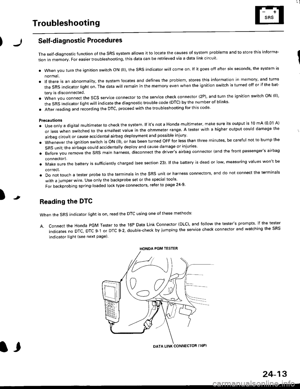
Reading the DTC
when the SRS indicator light is on, read the DTC using one of these methods:
A. Connect the Honda PGM Tester to the 16P Data Link Connector {DLC), and follow the tester's prompts lf the tester
indicatesnoDTc,DTcg-1orDTc9-2,doub|e-checkbyjumpingtheservicecheckconnectorandwatchingthesRS
indicator light (see next Page)
HONDA PGM TESTER
DATA LINK CONNECTOR Il6PI
l,
24-13
Page 1852 of 2189
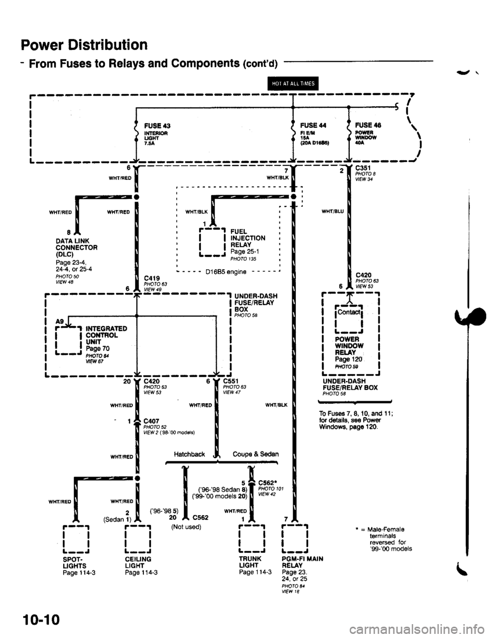
Power Distribution
- From Fuses to Relays and Components (cont'd)
-",JX-
I
I
\FUSE '3n{fEtbRUC|{T7.'.4
FUSE 44FI EA'!aacoa Dr6lc)
FUSE il8POUGNtvtl|Do{taoa
c351
c420PHOTO 63
I-.:CrJ
WIIT/ELX
1
I
I
I
I
FUELINJECTIONRELAYPage 25-1PHOTO 135
DATA LINKCONNECTOR(DLc)
Page 23-4,24-4, ot 25-4PHOfO 5001685 engine -
c419PHOTO 63
UNDER.DASHFUSE/RELAYBOXPHO|Q 5A
POWEBw]tDowNELAYPagE 120H$fa8
L-- ----- --20
wlIT/RED
-t
c420 6PHO|O 63vtEw 53
WHT/FEO
c407PHOTO 52Y|EW 2 ( 9& 00 modsrs)
c5s'rPHO|O 63
L-----JU DEN.DASHFUSE/RELAY BOXPHOfO 58
To Fuses 7, 8, 1 0, and I 1 ;tor deiails, s8€ PowerVYindotts, pa$ 120.
HatchbackCoup€ & S€dan
WHT/FED
(Sedan 1)
(e6-
101
,,, tr:::--*''.:lltut
(Not used)
i--l
tlL--J
TRUNKLIGHTPage 114-3
tl
tl
SPOT.LIGHTSPage 114-3
tl
tl
CEILINGLIGHTPage 114-3
* = Male-Femaleterminalsreversed for'99-'00 models
7A
tl
tl
PGM-FI MAINRELAYPage 23.24, ot 25
vtLw 18
I
I
PGM-FIRELAYPage 2324, ot 22
vtLw 18
i-,-x;-l
icontac{i
tlINTEGNATED
l__i!ffi*
10-10
Page 1863 of 2189
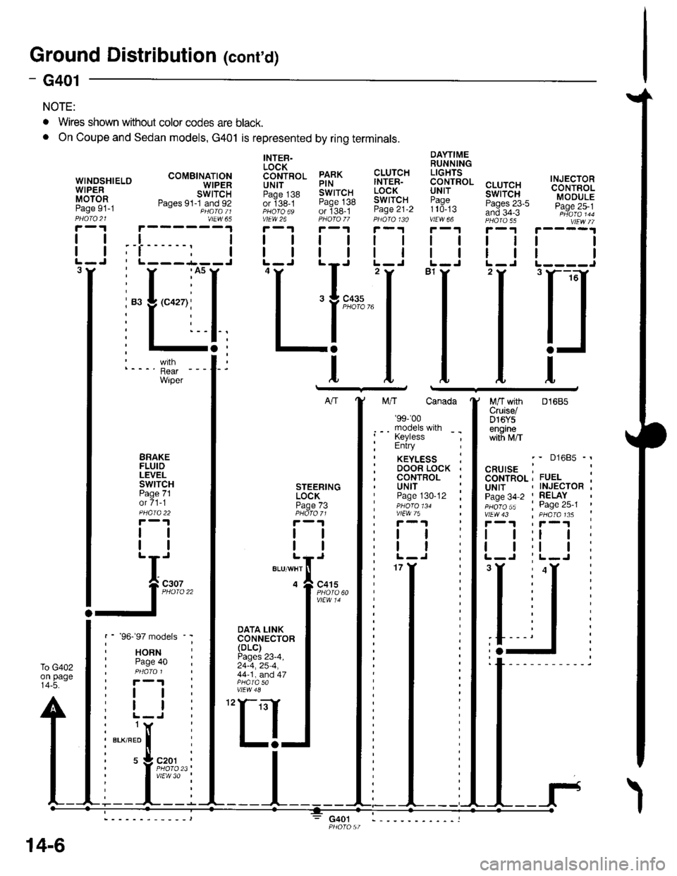
Ground Distributioh (conrd)
)
- G401
NOTE:
To G402on page14-5.
WINOSHIELOWIPERMOTORPage 91-1
DAYTIMERUNNINGLIGHTS
99.!rRoL cLUrcHuNr I swtTcH:?99^ Pases 23-5and 34-3vtEw 66 PHA|A 55
I
I
INJECTORCONTROLMODULEPage 25-1
I
I
3
. Wires shown without color codes are black.
o On Coupe and Sedan models, G401 is represented by ring terminals.
tl
tl
INTER.LOCK6611p99 PARKUN|T PINpaoe j38 SWITCHor ige_t Page 138PHoro6s of 138-1vtEw 26 PHOfO /7r-1 r-'t
tttl
CLUTCHINTER-LOCKSWITCHPage 21-2
ll
ll
ttl
rll
I
Itttl
'Ll;
I
n
t
M/T with 01685Cruise/D16Y5enginewith M/T
BRAKEFLUIDLEVELswtTcHPage 71ot 71-1
tl
tl
DOOR LOCK .CONTROLSTEERINGLOCKPage /3
tl
tl
UNITPage 130-12 ;
ttl
tt:
models
RNte 40
I
I
(
I
I czor
l'i1l?,
'97 mo
HORNPage 4
I
I
NFnl
s 9c.Plv'
BLK/RED
t
IJ;--
',f-l
DATA LINKCONNECTOR(DLC)Pages 23-4,24-4,25 4,44-1, and 47
30
14-6
G401
Page 2122 of 2189
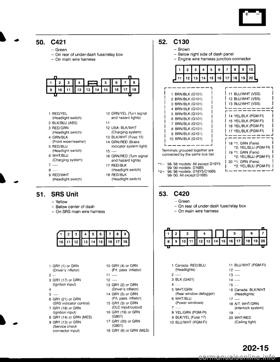
-50. c421
- Green- On rear of under-dash fuse/relay box- On main wire harness
I
l RED/YEL(Headlight switch)
2 BLIVBLU (ABS)
3 RED/GRN(Headlight switch)
4 GFIN/BLK(Front wiper/washer)
5 FED/BLU(Headlight swrtch)
6 WHT/BLU(Charging systern)
7
9 REDAVHT(Headlight switch)
10 GRN/YEL (Turn signaland hazard lights)
11
12 USA: BLKAVHT(Charging system)
13 BLKryVHT (Fuse 15)
14 GRN/RED (Brake
indicator system light)
16 GRN/RED (Turn signaland hazard lights)
17 BED/BLK(Headlight switch)
18 RED/BLK(Headlight switch)
52. C130
- Brown- Below right side ot dash panel- Engine wire harness junction connector
T---------"1
1 8RN/BLK (G101)
2 BRN/BLK (G101)
3 BRN/BLK (G101)
4 BRN/BLK (G101)
5 BRN/BLK (G101)
6 BRN/BLK (G101)
7 BRN/BLK (G101)
I BRN/BLK (G101)
9 BRN/BLK (G101)
10 BBN/BLK (G101)
L---------J
Terminals grouped together areconnected by the sarre bus bar.
*1= 96- 98 models: All except D16Y5'99-'00 models: D1685*2= 96-98 models: D16Y5/D1685'99- 00r All except D1685
11 BLUMHT (VSS)
12 BLU,ryVHT (VSS)
13 BLU,^/VHT (VSS)L_-_____--Jr---------'1
14 YEL/BLK (PGl\4-Fl)
15 YEL/BLK (PGr\4'Fr)
16 YEUBLK (PGI\4,FI)
17 YEUBLK (PGr\4,Fr)L______---JT----------118 *1: GRN (Fans)*2: YEUBLU (PGM-Fl)
19 *1: GRN (Fans).2: YEUBLU (PGM-Fl)
20 *1: GRN (Fans).2: YEUBLU (PGM-Fl)_______--J
51. SRS Unit
- Yellow- Below center oJ dash- On SRS marn wire harness
1 GFY (1) or GRN(Drivefs nflator)
2
3 GRY (17) or GRN(lgn tion input)
6 GRY (21) or GRN(SRS indicalor control)
7 GRY (18) or GRN(lgnition nput)
8 GBY (14) or GRN (MES)
9 GBY (13) of GRN(Service checkconnector input)
10 GRY (4) or GRN(Frt. pass. inflato4
11
13 GBY (2) or GRN(Drivefs nflator)
14 GBY (5) or GRN(Frt. pass. inflator)
15 GRY (3) or GRN(DLC input/output)
16 GRY (19) or GRN(G801)
17 GRY (20) or GRN(G801)
1B GRY (6) or GRN (MES)
13678
10Il12131415't7't8
53. C420
- Green- On rear of under-dash fuse/relay box- On main wire harness
1 Canadar RED/BLU(Headlights)
2
3 8LK (G401)
5 WHT/GRN(Rear window defogger)
6 WHT/BLU(Power windows)
7
8 YEL/GRN (PGM-FD
I BLK//EL (Fuse 17)
1O BLUAVHT (PGM,FI)
1 1 BLUMHT (PGI,4-FI)
14
16 Canada: BLKAVHT(Headlights)
18 A/Tr WHT/GRN(lnterlock system)
19
20 WHT/RED(Ceiling light)
202-15