2000 HONDA CIVIC Acc
[x] Cancel search: AccPage 35 of 2189

Warning/Caution Label Locations
A: CABLE REEL CAUTION A: '96 -99 model
TO SERVICE MANUAL FOR DETAILED INSTRUC.
TtoNs.
'00 model
ALLATION OF THE SRS CAELE REEL IS CRITICAL TO
THE PROPER OPERATION OF THE SRS SYSTEM. REFER TO
THE SERVICE MANUAL DETAILED INSTALLATION
INSTRUCTIONS.
(cont'd)
1-33
C: DRIVER MODULE OANGER
DANGEREXPLOSIVE/FLAMMABLECONTACT WITH ACIO. WATER OR HEAVY METALS SUCH
AS COPPER. I.EAD OR MERCURY MAY PRODUCE HARMFUL
AND IRRITATING GASES OR EXPLOSIVE COMPOUNDS,
STOBAGE TEMPERATURES MUST NOT EXCEED 2OO'F
I1(x}"CI. FOR PROPER HANDLING. STORAGE AND DISPOS.
AL PROCEDURES REFER TO SERVICE MANUAL. SRS SUP.
PLEMENT.POTSONCONTAINS POISONOUS SODIUM AZIOE AND POTASSIUM
NITRATE.FIRST AID:IF CONTENTS ARE SWALLOWED, INDUCE VOMITING, FOB
EYE CONTACT. FLUSH EYES WTTH WATER FOR 15 MINUTES.
IF GASES {FNOM ACIO OR WATEB CONTACTI ARE INHALED,
SEEK FRESH AIR. IN EVERY CASE, GET PBOMPT MEDICAL
ATTET,ITION.KEEP OUT OF REACH OF CHILDREN.
Br oRIVER MODULE WARNING
WARNINGTHE AIRBAG INFLATOR IS EXPLOSIVE AND, IF ACCIOEN-
TALLY DEPLOYEO, CAN SERIOUSLY HURT OR KILL YOU.. DO NOT USE ELECTRICAL TEST EoUIPMENT oR PROB-
ING OEVICES.THEY CAN CAUSE ACCIDENTAL DEPLOYMENT.o NO SERVICEABLE PARTS lNSlDE. DO NOT
DISASSEMBLE.. PLACE AIRBAG UPRIGHT WHEN REMOVED.. FOLLOW SERVICE MANUAL NSTBUCTIONS CAFEFULLY.
Page 37 of 2189
Llo
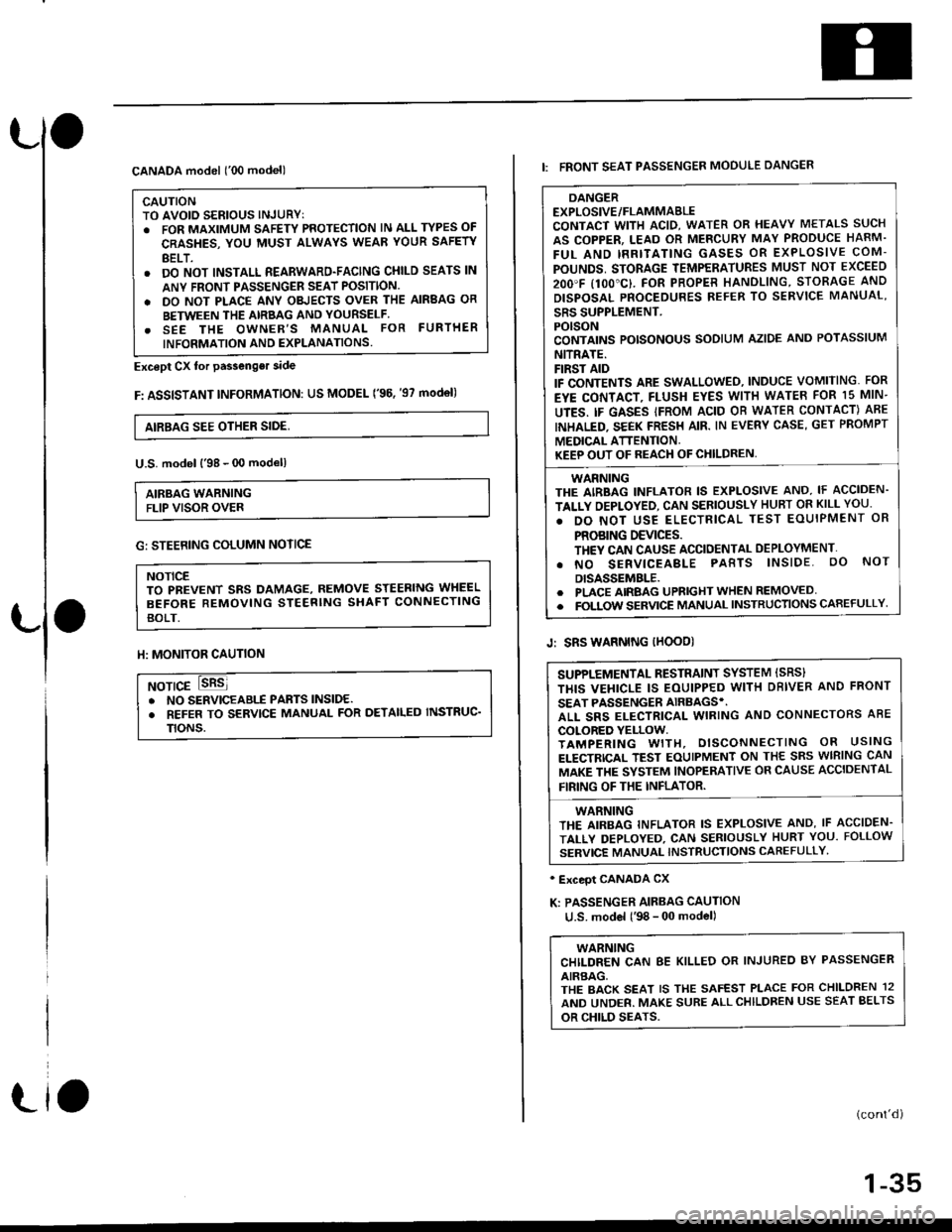
CANADA model ('00 model)
CAUTIONTO AVOID SERIOUS INJURYT. FOR MAXIMUM SAFETY PROTECTION lN ALL TYPES OF
CRASHES, YOU MUST ALWAYS WEAR YOUR SAFETY
BELT.. DO NOT INSTALL REARWARD-FACING CHILD SEATS lN
ANY FRONI PASSENGER SEAT POSITION.
. DO NOT PLACE ANY OBJECTS OVER THE AIRBAG OR
BETWEEN THE AIRBAG AND YOURSELF.. SEE THE OWNER'S MANUAL FOR FURTHER
INFORMATION AND EXPLANATIONS.
Except Cx tor passenger side
F: ASSISTANT INFoRMATION: US MODEL ('96. '97 mod€l)
AIRBAG SEE OTHER SIDE,
U.S. model l'98 - 00 modell
AIRBAG WARNINGFLIP VISOR OVER
Llo
G: STEERING COLUMN NOTICE
NOTICETO PBEVENT SRS DAMAGE, REMOVE STEERING WHEEL
BEFORE REMOVING STEERING SHAFT CONNECTING
BOLT.
ll: MONITOR CAUTION
NOTICE. NO SERVICEABIf PABTS lNSlDE.. REFER TO SERVICE MANUAL FOR DETAILED INSTRUC'
TtoNs.
DANGEREXPLOSIVE/FLAMMABLECONTACT WITH ACID, WATER OR HEAVY METALS SUCH
AS COPPER, LEAD OR MERCURY MAY PRODUCE HARM.
FUL AND IRRITATING GASES OR EXPLOSIVE COM-
POUNDS, STORAGE TEMPERATURES MUST NOT EXCEED
2OO'F I1OO"C}. FOR PROPER HANOLING, STORAGE AND
DISPOSAL PNOCEDURES REFER TO SERVICE MANUAL'
SRS SUPPLEMENT.POISONCONTAINS POISONOUS SODIUM AZIDE AND POTASSIUM
NITRATE.FIRST AIDIF CONTENTS ARE SWALLOWEO, INDUCE VOMITING. FOR
EYE CONTACT, FLUSH EYES WITH WATEB FOR 15 MIN-
UTES. IF GASES IFROM ACID OB WATER CONTACT) ABE
INHALED. SEEK FRESH AIR. IN EVERY CASE, GET PROMPT
MEDICAL ATTENTION.KEEP OUT OF REACH OF CHILDREN,
WARNINGTHE AIRBAG INFLATOR IS EXPLOSIVE AND, IF ACCIDEN-
TALLY OEPLOYED, CAN SERIOUSLY HUBT OR KILL YOU.
. DO NOT USE ELECTRICAL TEST EOUIPMENT OR
PROBING DEVICES.TH€Y CAN CAUSE ACCIDENTAL DEPLOYMENT'
. NO SERVICEABLE PABTS lNSlDE. oO NoT
DISASSEMBLE.. PLACE AIRBAG UPRIGHT WHEN REMOVED. FOLTOW SERVICE MANUAL INSTRUCTIONS CAREFULLY
I: FRONT SEAT PASSENGER MOOULE DANGER
Jr SRS WARNING IHOOD)
' Exceot CANADA CX
K: PASSENGER AIRBAG CAUTION
u.S. model l'98 - 00 model)
WARNINGCHILDREN CAN 8E KILLED OR INJUREO BY PASSENGER
AIRBAG,THE BACK SEAT IS THE SAFEST PLACE FOR CHILDREN 12
AND UNDER. MAKE SURE ALLCHILDREN USE SEAT BELTS
OR CHILD SEATS.
(cont'd)
1-35
SUPPLEMENTAL RESTRAINT SYSTEM ISRS}
THIS VEHICLE IS EOUIPPED WITH DBIVER AND FRONT
SEAT PASSENGER AIRBAGS'.ALL SRS ELECTRICAL WIRING AND CONNECTORS ABE
COLORED YELLOW.TAMPERING WITH, DISCONNECTING OR USING
ELECTRICAL TEST EOUIPMENT ON THE SRS WIRING CAN
MAKE THE SYSTEM INOPERATIVE OR CAUSE ACCIDENTAL
FIRING OF THE INFLATOR.
WARNINGTHE AIRBAG INFLATOR IS EXPLOSIVE AND, IF ACCIDEN.
TALLY DEPLOYED, CAN SERIOUSLY HURT YOU. FOLLOW
SERVICE MANUAL INSTRUCTIONS CAFEFULLY'
Page 39 of 2189
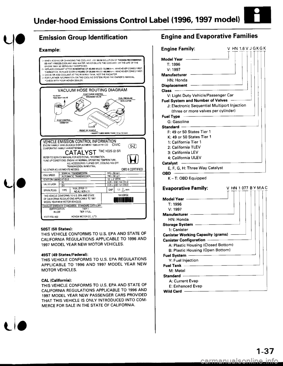
Under-hood Emissions Control Label (1996, 1997 model)
Emission
Example:
Group ldentification
VACUUM HOSE ROUTING DIAGRAM
50ST {50 States):
THIS VEHICLE CONFORMS TO U.S, EPA AND STATE OF
CALIFORNIA REGULATIONS APPLICABLE TO 1996 AND
1997 MODEL YEAR NEW MOTOR VEHICLES.
/$ST (49 States/Federall:
THIS VEHICLE CONFORMS TO U.S. EPA REGULATIONS
APPLICABLE TO '1996 AND 1997 MODEL YEAR NEW
MOTOB VEHICLES,
CAL (Calitornis):
THIS VEHICLE CONFORMS TO U.S. EPA AND STATE OF
CALIFORNIA REGULATIONS APPLICABLE TO 1996 AND,1997 MODEL YEAR NEW PASSENGER CARS PROVIDED
THAT THIS VEHICLE IS ONLY INTROOUCED INTO COM-
MERCE FOR SALE IN THE STATE OF CALIFORNIA.
-VEHICLE Ei/ ISSION CONTROL INFORMATIONE\G\. rrMrr vtsNrs\JLK6\Dsp-A(.MFN 590(--,. O CIVIC fa:n!APOF!]V4 -AV.t' !-rirorrSrMAc \Y:/
CATALYST IwcN02S{2)sFr
Fl.tarostq! tMA\uAttoaaooTo\a- \'oFM^ ro rt Tlr. \F Jo(O\D ' O\S E\Gr\l AINOnMA-OolqllNCTMoEqA Uql lH ia-LACCESSoT rS r-F\Eo0F C00ll\G -A 0( \-!-lJTRANSM1SSION N NEUTFAINO OTHERAOJUSIMENTS NEEDEO. O8D IICERTIFIED
IDLESPEEOATDC
NDr(Jl6CR.L1lr.r -i, "
TH SVEH CLE CONfOFMSTO U S. EPA AND STATEOF CALfORNIA RECULAI ONSAPPLICA8IElO 1997MOOET YEAR NEW MOTOR VEH CL'Silil]]lrl
Er!4#_"E!!ifl 4q!sq+HT-q4E!rL
N US€ TIEB l FULL
11211 .?2E AO2 HONDA MoTOR C0 , tTD
Engine and EvaPorative Families
Engine Family:V HN l.6VJGKGK
Model Year
T: 1996
V: 1997
T I
T|I
Manufacturer
HN: Honda
Displacem€nt
V: Light Duty Vehicle/Passenger Car
Fuel Systsm and Number of valves
J: Electronic Sequential Multiport Injection
(three or more valves per cylinder)
Fuel Type
G: Gasoline
Standard
F: 49 or 50 States Tier 1
K: 49 or 50 States Tier 1
1:California Tier 1
2: California TLEV
3: California LEV
4; California ULEV
Catalyst
E, F, G. H: Three Way Catalyst
OBD
K - T: OBD Equipped
Evaporative Family: v HN 1077 BYMAc'|T
Model Year
T:1996 |V:1997 lManufacturel
HN: Honda
Storage System
1:Canister
Canister Working Capacity (grams)
Canister Configulation
A: Plastic Housing (Closed Bottom)
B: Plastic Housing (oPen Bottom)
Fuel Systsm
Y: Fuel Injection
Fuel Tank
M: Metal
Standard
A: Current Evap
E: Enhanced Evap
Wild Card
1-37
Page 59 of 2189
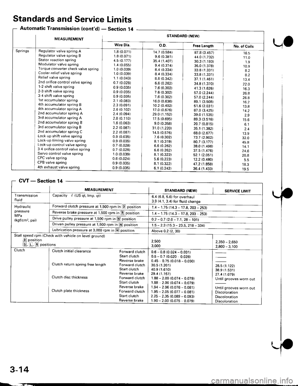
Standards and ServiceLimits
Section '14Automatic Transmission (cont'd)
UO
MEASUREMENTSTANDARD {NEW}
Wire Dia.o.D.Free LongthNo. ol CoilsHegulator valve spring ARegulato. valve spring BStator reaction springModulator valve springTorque convener check valve springCooler relief valve springRelief valve spring2nd oritice control valve spring1-2 shift valve spring2-3 sh ift valve spring3 4 shift valve spring'l st accumulator spring4th accumulator spring B4th accumulator spring A2nd accumulator spring A3rd accumulator spring A2nd accumulator spring B3rd acc!mulator spring B2nd accumulator spring CLock up shift valve springLock up timing valve springLock-up control valve spring3 4 ofifice control valve springServo control valve springCPC valve springCPB valve spring4th exhaust valve spring
Springs1.8 {0.071)1.8 {0.071)4.5 \O.117)1.4 (0.055)
1.0 10.039)1.0 (0.039)
1.1 (0.043)
0.7 (0.028)
0.9 (0.035)
0.9 (0.035)
0.9 (0.035)
2.1 (0.083)
2.3 (0.091)
2.610.102)2.4 (0.094)
2.8 (0.'110)
1.6 (0.063)
2.2 (0.087)
2.2 t0.041)0.9 (0.035)
0.9 (0.035)
0.7 (0.028)
0.7 (0.028)
1.0 (0.039)
0.6 (0.024)
0.9 {0.035)0.9 (0.035)
14.7 (0.584)
9.6 (0.381)
3s.4 (1.407)
9.4 (0.374)8.4 (0.334)
8.4 (0.334)
8.6 {0.342)6.6 (0.262)
7.6 (0.302)
7.6 (0.302)
7.6 (0.302)16.0 (0.636)10.2lo.402l17.0 {0.676)29.0 (1.152)
17.5 (0.6951
9.0 (0.358)
31.0 (1.220)
14.5 {0.576)7.6 (0.302)
8.1 (0.319)
6.610.262)6.6 (0.262)
8.1 (0.322)
5.6 (0.2231
8.1 10.322)6.1 10.242)
87.8 (3.457)
44.0 i.732l'30.3 (1.193)
35.0 {1.378)33.8 (1.331)
33.8 (1.331)
37.1 (1.461)
34.8 (1.370)
41.3 (1.626)
57.0 (2.2441
51 .0 \2.244189.1 {3.508)51.6 (2.031)
87.0 (3.425)
39.011.535)89.3 (3.516)
20.7 (0.815)
35.1 11.382)68.012.671173.7 12.902)80.7 (3.177)38.0 {1.496)37.5 fi.476)52.1 (2.051)
12.2 (0.480)
47.2 {1.858}36.4 {1.433)
16.511.01.910.94.24.213.422.016.326.826.a16.213.814.22.915.66.12.413.932.045.814.124.620.4
18.319.5
CVTSection 14
3-14
MEASUREMENTSTANDARD INEWISERVICE LIMITTransmissionfluidCapacity f {US qt, lmp. qt)6.4 {6.8, 5.6) for overhaul3.9 (4.1, 3.4) for fluid change
Hydraulicpressure
1kgflcm,, psi)
Forward clutch pressure at 1,500 rpm in E position1.4 - 1.15 114.3 - 11.A,203 - 2531Reverse brake pressure at 1,500 rpm in E position1.4 - 1.75 (14.3 11.8,203 2531Dr;ve pulley pressure at 1,500 rpm in E posrtrono.2 -0.7 12.0 -7.1,28- 1011Driven pulley pressure at 1,500 rpm in N positionr.5 - 2.3 115.3 - 23.5, 218 - 334)Lubrication pressure at 3,000 rpm in E posrtronAbove 0.212,30)Stall speed fpm (Check with vehicle on level ground)
E position
E, E, El positions2,5003,0002,350 - 2,6502,800 - 3, r00ClutchClutch initial clearance Forward clutchStart clutchReverse brakeClutch return spring free length Forward clutchStart clutchReverse brakeClutch disc thickness Forward clutchStart clutchReverse brakeClutch plate thickness Forward clutchSta rt clutchReverse brake
0.6 - 0.8 (0.024 - 0.031)0.5 - 0.7 (0.020 0.028)0.45 - 0.75 (0.018 - 0.030)30.5 {1.201)40.9 (1.610)
29.4 (1.157)
1.88 - 2.00 (0.074- 0.079)1.88 2.00 (0.074 - 0.079)1.94 - 2.06 (0.076 - 0.081)1.95 - 2.05 (0.077 -0.081)
2.25 2.35 (0.089 - 0.093)1.90 - 2.00 (0.075 0.079)
,*x.ar}38.9 (1.531)
27.411.019l'Until grooves worn out
Until grooves worn outDiscolorationDiscolorationDiscoloration
L.
Page 62 of 2189

Unit of length: mm lin)
STANDARD {NEW) SERVICE LIMITMEASUREMENT
Differential
Dtri"*"t"|p'.b"gear
S"t rrg-t" b""il"s
Pinion shaft contact area LD.
Carrier-to pinion clearanceDrive shaft contact area l.D.Carrier to driveshaft clearance
BacklashLD.Pinion gear to-pinion shafl clearance
)uter race clearance
18.010 18.028'0.7091 - 0.7098)
0.023 0.057 (0.0009 - 0.0022) 0.1 (0 004)
26.025 - 26.045 (.0246 1 0254\0.045 0.086 (0.0018 - 0.0034) 0.12(0.005)
0 05 - 0.15 i0 002 0.006)18 042 18.066 {0.7103 0.7" l3)
0.055 - 0.095 (0.0022 - 0.0037) 0.15 {0.006)
0 0.15 (0 - 0.006) Adjlrst
MEASUBEMENT Wire DiaO.D. Free Length I No. of Coils
SpringsPH regulator valve spring 1 2 (0 047)
PH control valve spring 1 7 {0.067)PL regulator valve spring 0 9 (0.035)
PH'PL control valve spring 1 0 (0 039)
crutlh reduc'ns vdrve spnns ] :19 9]:lLLbrication valve spring I b (u ubJr
Shitt valve spring 1 4 (0.055)
Shift control valve spring 1 0 (0.039)
Stan clutch control valve spring 0.4 (0 016)
Pitot regulator valve spring 0.6 (0 024)
Start clutch valve accumulator spring 1 2 \0 O47)
Reverse control valve spring 1 2 (0.047)
Shift inhibitor valve spring 1 3 (0 051)
9.0 {0.354)13.4 (0.528)
1.2lO.2A3\10.0 (0.394)
16.8 (0.661)
13.4 (0.528)
8.2 (0.323)
1 .4 t0.29114.1 (0.161)
5.7 t0.224)8.3 {0.327)9.4 (0.370)
13.2 (0.520)
26.7 (1.051)
39.4 (1.551)
14.6 (0.575)
31.4 (1.236)
44.4 \1.14al51.6 (2.031)
34.1 (1.343)
19.3 (0.760)
12.1 (0.476)
9.5 (0.374)
29.8 (1.173)
31.4 (1.236)
48.3 (1.902)
r0.08.11.28.68.0
13.01.56.85.012.311.010.6
Section 14
SteeringSection 17
M/S: [,4anual steering, P/Sl Power steering*: When using a ne; bett, adjust dellection or tension to new values. Run the engine for 5 minutes then turn it off-
Readjust the deflection or tension to used belt values.
cw
MEASUREMENTSTANDARD {NEWI
Steering wheelPlay at steering wheel circumferenceStarting load at steering wheelcircumferenceN (ksf, lbf)Manual steeringPower steering Engine running
0 - 10 (0 0.4)
15 (1.5,3.3)
29 (3.0,6.6)
GearboxAngle of rack guide screw loosened M/S
from locked position P/S
Preload at pinion gear shaft N m (kglcm, lbfin) M/S
20!5"20'Max0.5 - 1.7 (5 - 17,4.3 - 14.8i
0.6 1.2 (6 - 12, 5.20 - 10.42)
Pump pressure with valve closed(oil temp./speed: 40'C (105"F) min./idleDo not run for more than 5 seconds).kPa (kgtcm?, psi)
6,400 - 7,400 {65 - 75, 920 - 1,070)
Power steeringfluidRecommended power steering fluid
Fluid capacity | {US qt, lmp q0Reservoir
HONDA Power Steering Fluid
0.85 (0.90,0.75) at disassembly0.4 {0.42.0.35}
7.5 11.0 {0.30 - 0.43)with used belt
5.0 7.0 (0.20 0.28) with new belt10.5 - 14.0 10.41 - 0.55) with used belt7.5 10.010.30 0.39) with new belt
390 540 {40 55,88 '120) wrth used bek
340 - 490 (35 - 50, 77 - 110) with used belt
740 880 (75 - 90, 170 - 200) with new belt
640 780 (65 - 80, 143-176)with newbelt
Power steeringbelt*
Deflection with 98 N (10 kgf,22 lbf)
between pulleys '99 modell 81642 Engine Type only
'96 '99 models: Other Engine TYPes
ron.ionffiN (kgf, lbf) '99 model: 81642 Engine Tvpe only'96 -'99 models: Other Engine TYPes'99 modelr 81642 Engine TYPe onlY'96 '99 models: Other Engine TYPes
3-17
Page 99 of 2189
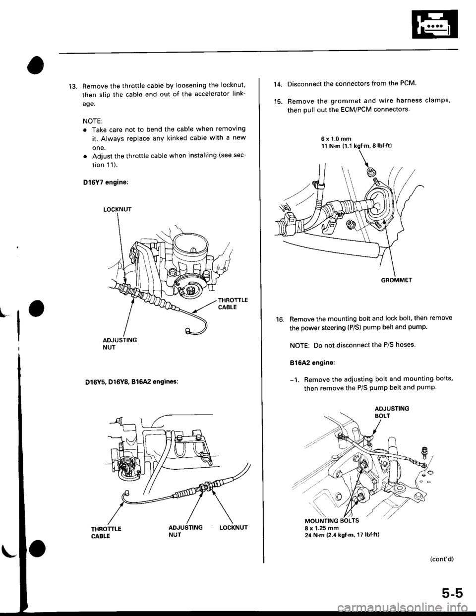
13. Remove the throftle cable by loosening the locknut,
then slip the cable end out of the accelerator link-
age.
NOTE;
. Take care not to bend the cable when removing
it. Always replace any kinked cable with a new
one.
. Adjust the throttle cable when installing (see sec-
tion 1 1).
D16Y7 engine:
D16Y5, D16Y8, B16A2 engines:
LOCKNUT
LOCKNUT
14,Disconnect the connectors from the PCM.
Remove the grommet and wire harness clamps,
then pull out the ECM/PCM connectors
6x1.0mm
16. Remove the mounting bolt and lock bolt, then remove
the power steering (P/S) pump belt and pump
NOTE: Do not disconnect the P/S hoses.
816A2 engine:
Remove the adjusting bolt and mounting boits,
then remove the P/S pump belt and pump
(cont'd)
5-5
AOJUSTING
Page 114 of 2189

VTEC Control System
Troubleshooting Flowchart
tFtrsrl #ilH:::lj1t:"J:T,?ffnostic
rrouble code (Drc) Pr25e: A probrem in the vrEc Pressure switch circuit or
Reter to page 1 l-38 th roug h 1 1-55 before trou bleshooting.
* Road Test:Accelerate in 1st gear to an engine speed over 3,000 rpm(D16Y5 engine) or 6,000 rpm (D'16Y8 engine).Hold that engine speed for at least two seconds.It DTC P1259 is not repeated during the first road test, repeatthis test two more tames.
VTEC PRESSURE SWITCH 2PCONNECTOR
Terminal side ofmale terminals
Wire sid6 ol femalerermtnats
VTM
l1 (BLu/BLK)
f;-) |I
I
Y
I
The MIL has been reoorted on.DTC P1259 is sto.ed.
Check the VTEC Cont.ol Syst6m:1. Do the engine control module(ECM)/powertrain control module lPCM) Reset Procedure (see
section 11).2. Stan the engine.3. Warm up the engine to normaloperating temperature (cool-
ing fan comes on).4. Do the Boad Test.*Intermittont tailura, 3y3t.m is OKat thia time.Check for ooor connoctionr o.loose wirea at VTEC oiassurclwitch, VTEC solonoid valvo .ndECM/PCM,
ls OTC P1259 indicated?
Test rhe VTEC Prensure Switch:1. Turn the ignition switch OFF.2. Disconnect the VTEC Pressureswitch 2P connector.3. Check for continuity betweenVTEC pressure switch 2P con-nector terminal No. 1 and No.2.
Replace the VTEC preasure 3witch.ls there continuity?
Te3t the VTEC Pressure SwitchWire:1. Turn the ignition switch ON lll).2. Measure the voltage betweenVTEC press u re switch 2Pconnector No. l and bodyground.
In3poct for en opon or shod toground in thG wi.. bctwoon thoVTEC pro$ur6 switch rnd ECM/PCM l'96 - 9a: C15,'99 - 00: C101.lf tha wiro i3 OK,3ubrtitute aknown-good ECM/PCM andrecheck.
ls there battery voltage?
{To page 6'4i
Page 130 of 2189
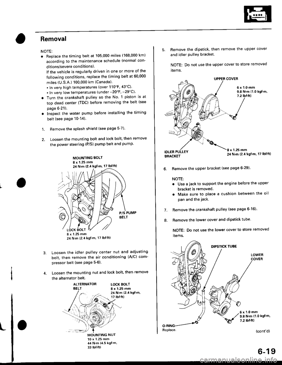
Removal
NOTE:
. Replace the timing belt at 105,000 miles (168.000 km)
according to the maintenance schedule (normal con-
ditions/severe conditions).
lf the vehicle is regularly driven in one or more of the
followlng conditions, replace the timing belt at 60.000
miles (U.S.A.) 100,000 km {Canada).
.In very high temperatures (over 110'F.43'C)
. In very low temperatures (under -20'F, -29"C)'
! Turn the crankshaft pulley so the No. 1 piston is at
top dead center (TDC) before removing the belt (see
page 6'21).
. Inspect the water pump before installing the timing
belt {see Page 10-14).
1. Remove the splash shield (see page 5-7).
2. Loosen the mounting bolt and lock bolt. then remove
the power steering (P/S) pump belt and pump
MOUNTING BOLT
8 x 1.25 mm2il N m 12.4 kgl m, 17 lbf'ft)
P/S PUMPBELT
I x 1.25 mm24 N m (2.4 kgf m, 17 lbt ft)
Loosen the idler pulley center nut and adjusting
bolt, then remove the air conditioning (AVC) com-
pressor belt (see Page 5-6).
Loosen the mounting nut and lock bolt, then remove
the alternator belt.
ALTERNATORBELTLOCK BOLTI x 1.25 mm24 N.m 12.4 kgf.m,r? tbI.ft)
3.
MOUNTING NUT10 x 1.25 mm44 N.m 14.5 kgl m,
33 rb{ ft)
5. Remove the dipstick, then remove the upper cover
and idler PulleY bracket
NOTE: Do not use the upper cover to store removed
items.
6x1.0mm9.8 N.m 11.0 kgf.m,7.2
IDLERI x 1.25 mm24 N.m (2.4 kgl.m, 17 lbf'ft)BRACKET
6. Remove the upper bracket {see page 6-29)
NOTE:
. Use a jack to support the engine before the upper
bracket is removed
. Make sure to place a cushion between the oil
pan and the jack.
Remove the crankshaft pulley (see page 6-16).
Remove the lower cover and dipstick tube
NOTE; Do not use the lower cover to store removed
items.
1.
.'.
DIPSTICK TUBE
LOWER
6x1.0mm9.8 N.m (1.0 kgf m,
7.2 rbt.ft)
(cont'd)
6-19
Replace.