2000 HONDA CIVIC trans
[x] Cancel search: transPage 486 of 2189

t
L
(From page 11-216)- Repair open in the wire
between the ECM {C291 and
lhe Ituge assomblv.- Repair open in the wire
betwoen the gauge assembly
and the A/T gea. Positionswitch.
ls there less than 1.0 V?
Chock for a short in the wite (ATP
NP line):Measure voltage between ECM
connector terminals Ag and C29
with the transmission in gear.
ReDair short in the wire be'tween
ECM (C291 and gauge a3somblY.ls there battery voltage?
A/T g€ar position signal is OK
LG1 IEBN/BLK)
ECM CONNECTORS
ATP NPWire side of female terminals (LT GRN)
Page 491 of 2189

ldle Control System
ldle Speed Setting (cont'dl
Inspeqtion/Adiustment
38 D16Y5 engine whh M/T,'99 - 00 81642 engine
NOTE: Before setting the idle speed, check the follow-ing items;- The MIL has not been reported on.- lgnition timing- Spark plugs- Air cleaner- PCV system
'1. Start the engine. Hold the engine at 3,000 rpm withno load (transmission in neutral) until the radiatorfan comes on, then let it idle.
Connect a tachometer.
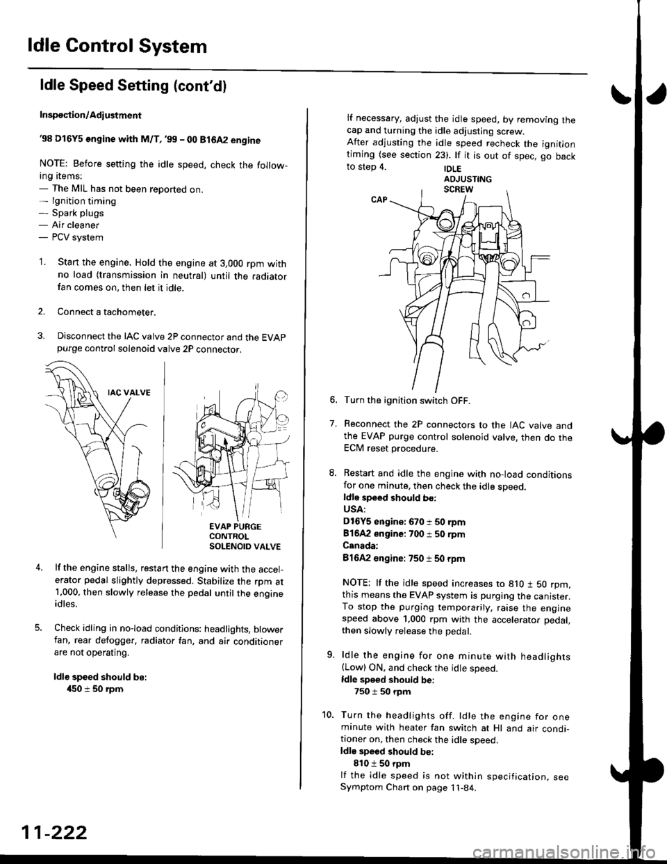
Disconnect the IAC valve 2P connector and the EVAPpurge controlsolenoid valve 2P connector.
EVAP PURGECONTROLSOLENOID VALVE
lf the engine stalls, restart the engine with the accel-erator pedal slightly depressed. Stabilize the rpm at1.000, then slowly release the pedal until the engineidles.
Check idling in no-load conditions: headlights, blowerfan, rear defogger, radiator fan, and air conditionerare not operating.
ldl€ speed should be:
450 i 50 rpm
11-222
lf necessary, adjust the idle speed, by removrng lnecap and turning the idle adjusting screw.After adjusting the idle speed recheck the ignitlontiming (see section 23). lf it is out of spec, go backto step 4. |DLE
6. Turn the ignition switch OFF.
7. Reconnect the 2P connectors to the IAC valve andthe EVAP purge control solenoid valve, then do theECM reset procedure.
8. Restart and idle the engine with no-load conditionsfor one minute, then check the idle sDeed.ldle speed should bo:
USA:
D16Y5 engine: 670 i 50 rpm
81642 engine: 700 i 50 rpm
Canada:
81642 engine: 750 t 50 rpm
NOTE: lf the idle speed increases to 8lO t 50 rpm,this means the EVAP system is purging the canister.To stop the purging temporarily, raise the enginespeed above 1,000 rpm with the accelerator pedal,
then slowly release the pedal.
9. ldle the engine for one minute with headlights(Low) ON. and check the idle speed.
ldle speed should be:
750 i 50 rpm
10. Turn the headlights off. ldle the engine for oneminute with heater fan switch at Hl and air condi-tioner on, then check the idle soeed.ldls speed should be:
810 t 50 rpm
lf the idle speed is not within specification, seeSymptom Chart on page 11-84.
Page 492 of 2189

\
I
'98 - 0O D16Y5 ongine with CvT
Adjust the idle speed using a Honda PGM Tester if pos-
sible. lf not, use the following procedure:
NOTE:
. Leave the IAC valve connected.
. Before s€tting the idle speed, check the following
rtems:- The MIL has not been reported on.
- lgnition timing
- Spark Plugs- Air clean€r
- PCV svstem
'1. Connect a tachometer.
2. Stan the engine. Hold the engine at 3,000 rpm w'th
no load (transmission in E or E] position) until the
radiator Jan comes on, then let it idle.
3. Check the idle speed under no-load conditions:
head lights, blower fan, rear defogger, radiator fan,
and air conditioner are not operatlng.
ldlo spaod ehould bo: 700 t 50 rpm
. lf the idle speed is within the specification, the
procedure is comPlete.
. lf the idle sDeed is out of specitication, 9o to step 4'
4. tf the idle speed is 810 1 50 rpm, this means the
EVAP system is purging the canister. To stop the
purging temporarily, raise the engine speed above
l,OO0 rgm with the accelsrator pedal. Slowly release
the pedal. and rscheck the idl€ speed.
. tf the idle speed is within the specificstion, the
Drocedure is comPlete.
. lf the idle sp€ed is out of spocification, go to step 5.
5. Disconnect th€ EVAP purgs control solenoid valve
2P connector.
EVAP PURGECONTROL
6. Remove the cap and turn the idle adiusting screw
1/2-turn clockwise or counterclockwlse
IDLE
7.After turning the idle adjusting screw 1/2-turn, check
the idl€ speed again. lf it is out of spec, turn the idle
adjusting screw 1/2-turn again.
NOTE: Do not turn the idle adjusting screw more
than 1/2-turn without checking the idle speed.
Turn the ignition switch OFF. Reconnect the EVAP
purge control solenoid valve 2P connector' then do
the ECM reset Procedure.
Start the engine. ldle the engine for one minute with
heater fan switch at Hl and air conditioner on, then
check the idle speed.
ldle spaed should be:
810 t 50 rpm (in El or E Posiiion)
lf the idle speed is not within specification, see
Svmptom Chart on Page 11-84.
9.
SOLENOID VALVE
11-223
Page 507 of 2189

Fuel Supply System
PGM-FI Main Relay (cont'dl
Circuit Troubleshootin g
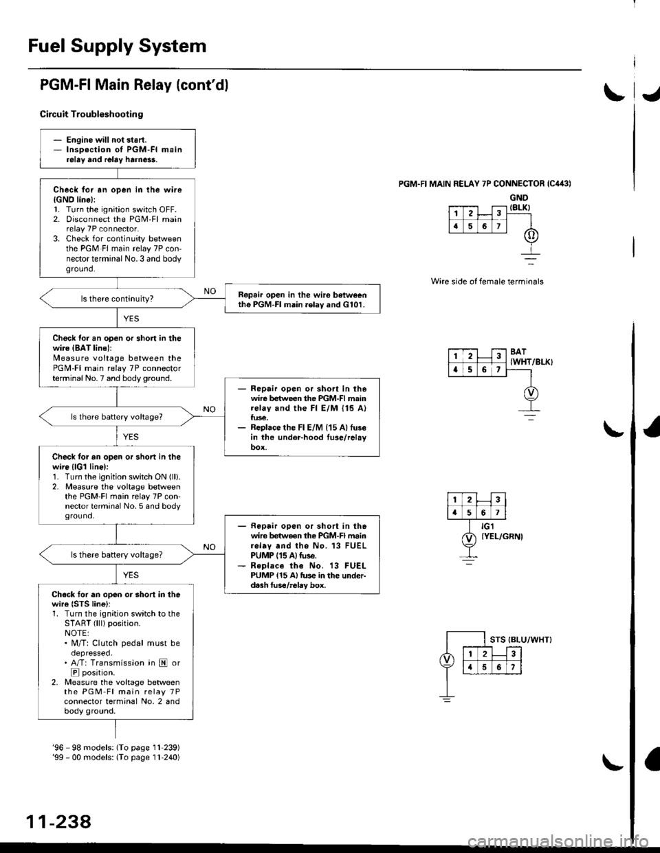
PGM.FI MAIN RELAY 7P CONNECTOR {C443)
GND{8LK)
Wire side of female terminals
/BLK}
- Engine will not start.- lnsoection of PGM-FI mainrelay and relay harne$.
Check for an open in the wire{GNO line}:l. Turn the ignition switch OFF.2. Disconnect the PGM-Fl mainrelay 7P connector.3. Check for continuity betweenthe PGM Fl main relay 7P con-nector terminal No.3 and bodyground.
Ropai. open in the wir€ betweenthe PGM-FI main .elav and G101.
Check for an open or short in thewire {BAT lin€}:N4easure voltage between thePGM-FI main relay 7P connectorterminal No. 7 and body ground.- Repair open or sho.t in thewire between the PGM-FI mainrelay and the Fl E/M {15 A}fus€.- Replace the Fl E/M (15 Allu3ein the under-hood fuse/relayoox.
ls lhere battery voltage?
Check tor an open or short in thewire {lGl line):1. Turn the ignition switch ON (ll).
2. Measure the voltage betweenthe PGM-Fl main relay 7P con'nector terminal No. 5 and bodyground.- Repair open or short in thewire betwoen the PGM-FI mainrelav and the No. 13 FUELPUMP (15 A)tuse.- R€place the No. 13 FUELPUMP {15 A} tus€ in the under-d.sh fus€/relay box.
ls there battery voltage?
Ch.ck for an open or short in thewire {STS lino}r1. Turn the ignition switch to theSTART (lll) position.NOTE:. M/T: Clutch pedal must beoepresseo.. A/T: Transmission in E or
E position.2, Measure the voltage betweenthe PGM-Fl main relay 7Pconnector terminal No, 2 andbody ground.
12
[,a567
123BAT
{WHTa56,
'96 98 models: (To page 1l 239)'99 - 00 models: (To page I l-240)
11-238,
Page 530 of 2189

\JExhaust Gas Recirculation System (D16Y5 engine with M/T)
M/T:
EGR VALVE 6P CONNECTOB (C14'rl
G10lIBLK}
1
a
PNK
IE.EGRI
Wi16 side of male terminals
I
sG2{GRN/BLK}
vcc2{YEL/BLU)
- Th6 MIL ha3 b€on reponed on.- DTC Pl,{tl is 3tored.
Prcblem verification:1. Do the ECM Reset Procedure.
2. Connect the SCS service con_nector.3. Start the engine. Hold the
engine at 3,000 rpm with no
load (transmission in neutral)
untilthe radiator fan comes on.
4. Drive the vehicle on the road
for approx. 10 minutes. Try to
keep the engine speed in the
1,700 - 2,500 rpm range.
lnlermittont tailure, svalem is OK
at thi3 tim6. Check foi Poor con'
nections or looso wiro3 at Cl/K
IEGR valvsl and ECM.
ls DTC P1491 indicated?
Check tor a malfunction in the
EGR valv6:1. Turn the ignition switch OFF.
2. Disconnect the EGR valve 6P
connector.3. Stanthe engine and let it idle
4. Measure voltage between the
EGR valve 6P connector termi'
nals No.4and No.6.
Check the EGR valve:1. Turn the ignition switch OFF2. Turn the ignition switch ON lll).3. Measure voltage between theEGR valve 6P connector termi
nals No.2 and No.3.
ls there battery voltage?
Substitute a known-good ECM
and recheck. It symptom/indica_tion goes away, replace th€ origi-
nal ECM.
ls there approx.5V?
(To page 11-262)
Page 554 of 2189

\
\
(From page 11-284)
\(cont'd)
11-285
EVAP PURGE CONTROL SOI.INOID
VALVE 2P CONNECTOR IC114I
Wire side otfemaleterminals
?,
I,l,lil?"",,,u
EL,TWYEL)
Check the EVAP pirrge controlsolenoid valvei1. Disconnect the 2P connector
lrom the EVAP purge control
solenoid valve.
2. Ouickly raise the engine speed
to 3,000 rpm.
ls there vacuum?
InsDect vacuum ho56 routing.ll OK, replace the EVAP Purgecontrol solenoid valve.
Chock for a short in the wire(PCS linel:1. Turn the ignition switch OFF
2. Disconnect ECM/PCM connec'
tor A (32Pi.
3. Check for continuity between
the EVAP PUrge control sole
noid valve 2P connector termi
nal No.2 and body ground.
Check the vacuum when hot:
1. Turn the ignition switch OFF
2. Block the rear wheels and set
the parking brake.3. Jack up the front o{ the vehi-
cle and support it with safety
stands,4. Start the engine. Hold the
engine al 3,000 rpm wlth no
load (in Park or neutral) until
the radiator fan comes on, then
let it idle.5, Check for vacuum at the vac-
uum hose with transmissaonin gear (A/T in B Position,M/T in lst gear) after starting
the engrne.6. Ouickly raise the engine speed
to 3,000 rpm.
Reoair short in the wire botween
the EVAP purg€ cor|t]ol solenoid
valve and the ECM/pcM lA15l.ls there continuity?
Substitute a known-good ECM/
PCM and recheck. lf sYmPtom/indication goes eway. repl.c€ the
original ECM/PCM.
Check the EVAP Purg€ control
solenoid valve:1. Turn the ignition switch OFF
2. Disconnect the 2P connector
from the EVAP Purge control
solenoid valve and warm lt
up to normal operating tem_perature again if necessary
3. Stan the engine.4. At the harness side, measure
voltage between the EVAP
Purge control solenoid valve
2P connector terminal No. 1
and No. 2 with the transmission in gear (A,/T in E Posi-tion, M/T in 1st gear).
In3pect vacuum ho3€ touting.
ll OK, replace EVAP Purge con-
lrol aolenoid vtlv€.
Check lo. an open in the wire
llGl linel:At the harness side, measure volt
age between the EVAP Purge con-
trol solenoid valve 2P connectorterminal No. 1 and body groundRepeir open in tho wire between
EVAP purge conttol solenoid valv€
and the No. 15 ALTERNATOR SP
SENSOR (7.5 A fu3e
IBLK/YELI
lTo page 11 286i(To page 11-286)
Page 559 of 2189

Emission Control System
Ch€ck the EVAP purge controlsolenoid valv6:1. Disconnect the 2P connectorfrom the EVAP purge controlsolenoid valve.2. Ouickly raise the engine speedto 3,000 rpm.
Insped vacuum hose routing.lf OK. roplace the EVAP purge
control solonoid valve.
Chock tor r short in the wir€
{PCS line):1. Turn the ignition switch OFF.2. Disconnect ECM/PCM connec-tor A (32P).
3- Check tor continuity betweenthe EVAP purge control sole-noid valve 2P connector termi-nal No. 2 and body ground.
Check the vacuum when hot:1. Turn the ignition switch OFF.2. Block the rear wheels and setthe parking brake.3. Jack up the lront of the vehi-cle and support it with safetystands.4. Start the engine. Hold theengine at 3,000 rpm with noload (in Park or neutrali until
the radiator fan comes on, thenlet it idle.5. Check for vacuum at the vac-uum hose with transmissionin gear (A/T in E position,
lvl/T in 1st gear) after startingthe engine.6. Ouickly raise the engine speedto 3,000 rpm.
Rooair shoft in the wire belwegnthe EVAP pulg6 control solenoidvalvs and tho ECM/PCM {A61.ls there continuity?
Substitute a known-good ECM/PCM and rech6ck. lt 3ymptom/indicrtion 90e3 rway, r6plac6 th€o.iginal ECM/FCM.
Check th€ EVAP purge controlsolenoid valve:1. Turn the;gnition switch OFF.2. Disconnect the 2P connectorfrom the EVAP purge controlsolenoid valve and warm itup to normal operating tem-perature again if necessary.3. Start the engine.4- At the harness side, measurevoltage between the EVAPpurge control solenoid valve2P connector terminal No. 1and No.2 with the transmis-sion in gear {A/T in E posi-tion, M/T in lst geari.
In3pect vacuum hoae routing.lf OK, repl.ce EVAP purge con-trol solonoid valve.ls there battery voltage?
Chock for an open in the wire(lG1 lina):At the harnoss side, measure volt-age beNveen the EVAP purge con-trol solenoid valve 2P connectorterminal No. 1 and body ground.
Repair open in the wire b€lwe€nEVAP purge contrl 3olenoid valv6and lhe No. 15 ALTERNATOR SPSENSOR 17.5 A, fu3e.
ls there battery voltage?
Evaporative Emission (EVAPI Controls (cont'dl
(From page 11-289)
(To page 11-291)
11-290
IJ
EVAP PURGE CONTROL SOLENOIDVALVE 2P CONNECTOR IC114I
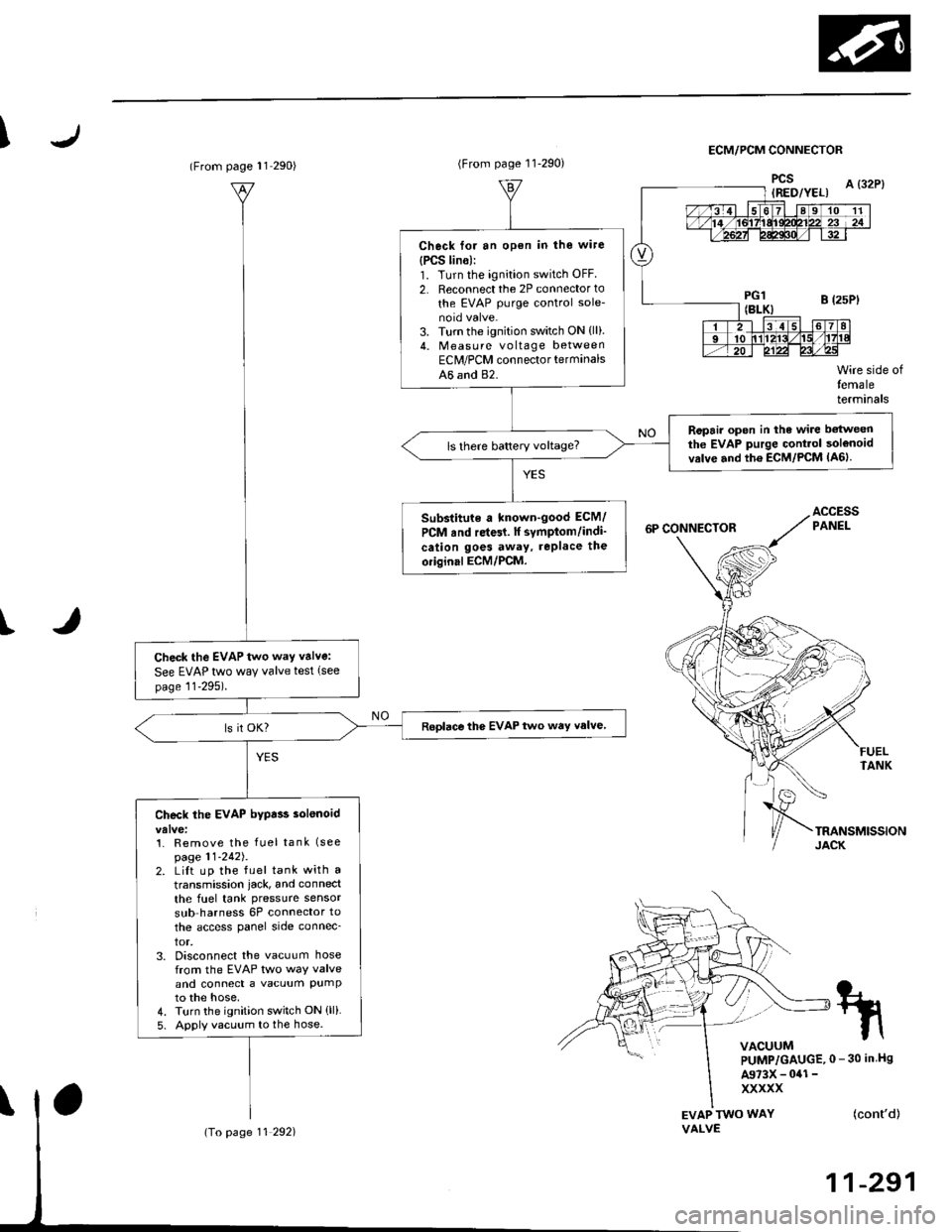
PCS
IRED/YEL)
temaletermrnars
of
PCS(RED/YEL)
tGlIBLK/YEL)
{To page 11 291)
Page 560 of 2189

IECM/PCM CONNECTOR
I
EVAP TWO WAYVALVE
Wire side oftemaleterminals
FUELTANK
(cont'd)
11-291
tn
VACUUMPUMP/GAUGE,0 - 30 in Hs
A973X - 041 -
xxxxx
(From page l1 290)
Check the EVAP two way valve:
See EVAP two way valve test (see
page 11-295).
Roplace the EVAP two way valve
Check the EVAP bypa$ solenoid
1. Remove the fuel tank (see
page 11-242J.2. LiIt up the fuel tank with a
transmission iack, and connect
the fuel tank pressure sensor
sub harness 6P connector to
the access panel side connec_
tor,3. Disconnect the vacuum hosefrom the EVAP two way valveand connect a vacuum PumPto the hose,4. Turn the ignition switch ON (ll)
5. Apply vacuum to the hose.
(To page 11 292)
(From page 11-290)
Check for an open in the wire
{PCS lin6):1. Turn the ignition switch OFF
2. Reconnect the 2P connector to
the EVAP purge control sole-
3. Turn the ignition switch ON {ll).4. Measu re voltage betweenEClr/PCM connector terminals
A6 and 82.
Ropair open in the wire betweenthe EVAP purge Gontrol solenoidvrlve and th6 ECM/PCM lA6lls there battery voltage?
Substitute a known-good ECM/
PCM rnd re{61. lf symptom/indi'
cation goes away, rePlace the
oiiginal ECM/PCM.