Page 798 of 2189
Pressure Testing
(cont'd)
Line Pressure/1st Clutch Pressurc Measurement
1. Set the parking brake, and btock both rear wheels securely.
2. Start the engine, and run it at 2,OOO rpm.
3. Shift to N or E position, then measure line pressure.
NoTE: Higher pressure may be indicated if measurements are made in shift lever positions other than @ or @ positron.
4. Shift to tq;l position, hold the engine at 2,000 rpm, and measure 1st crutch pressure.
1ST CLUTCH PRESSUREINSPECTION HOLE(Marked with "1")
LOCK.UP CONTROLSOLENOID VALVE A/8ASSEMBLY
VALVE A/B ASSEMBLY
PRESSURESHIFT LEVER
POS|TtONSYMPTOMPROBABLE CAUSEFLUID PRESSURE
StandardService Limit
LineN orENo (or low)
lrne pressureTorque converter,
ATF pump, pres-
sure regutator.
torque converter
check valve
830 - 880 kPa
{8.5 - 9.0 kgf/cm?,
120 - 130 psi)
780 kPa(8.0 kgf/cm'�, 110 psi)
1st ClutchD;lNo or low 1st
pressure
1st Clutch
\
14-120
Page 803 of 2189
19. Remove the engine stiffener and the torque con-
verter cover.
Remove the eight drive plate bolts one at a tlme
while rotating the crankshaft pulley.
Remove the distributor.
Attach a hoisting bracket to the engine, then lift the
engine slightly.
HOISTBRACKET
20.
21.
COVER
23. Place a jack under the transmission. and ra6a :'.
transmission iust enough to take weight otf ol tF.
mounts. then remove the transmission mounl
TRANSMISSIONMOUNT BRACKET
Remove the transmission housing mounting bolts
and the rear engine mounting bolts.
Pull the transmission away from the engine until it
clears the 14 mm dowel pins, then lower it on the
transmission jack.
TRANSMISSION HOUSING
lf necessary, remove the torque converter anc:"
starter motor.
24.
25.
1+16
Page 805 of 2189

O ROLLER
O COLLAR
O o-RING Replace.
@ FEED PIPE FLANGE
@ O-RING Replace.
@ SNAP RING
€) 3RD CLUTCH FEED PIPE
€) COUNTERSHAFT LOCKNUT (FLANGE NUT)
23 x 1.25 mm Replace.
o coNlcAL SPRING WASHER Replace.
@ PARK GEAR
@ ONE.WAY CLUTCH
@ COUNTERSHAFT lST GEAR
@ NEEDLE BEARING
@ COUNTERSHAFT lST GEAR COLLAR
@ o-RlNGs Replace.
@ END covER GASKET Replace.
E) DOWEL PINS
@ PARK PAWL STOP
@ LocK WASHER Replace.
@ PARK STOP Selective part
€D PARK LEVER
@ PARK LEVER SPRING
€D DRAIN PLUG
€) SEALING WASHER Replace
@ o-RING Replace.
@ COUNTERSHAFT SPEED SENSOR
@) PARK PAWL
@ PARK PAWL SPRING
@ PARK PAWL SHAFT
@ LINEAR SOLENOID ASSEMBLY
@ LINEAR SOLENOID GASKET REPIACE.
@) END COVER
@ lsT CLUTCH FEED PIPE
@ O-RINGS Replace.
@ FEED PIPE FLANGE
C) SNAP BING
@ MAINSHAFT LOCKNUT (FLANGE NUTI 21 x 1 25 mm
Replace.
@ CONICAL SPRING WASHER RePlace
@) lST CLUTCH ASSEMBLY
@ o-RlNGs Replace.
€) THRUST WASHER
@) THRUST NEEDLE BEARING
@ NEEDLE BEARING
@ MAINSHAFT lST GEAR
@ MAINSHAFT lST GEAR COLLAR
@) ATF COOLER LINE
@ SEAUNG WASHERS Replace.
@ LINE BOLT
@ ATF DIFSTICK
@ ATF COOLER LINE
@ UNE BOLT
@ SEALING WASHERS Replace.
@ VEHICTT SPEED SENSOR
@ O-RING Replace.
TOROUE SPECIFICATIONS
Bolt/Nut No.Torque ValueSizeRemarks
6B
8F
12A.'l8D
2'tM
23C
'12 N'm (1.2 kgim,8.7 lbift)
14 N.m (1.4 kgf.m, 10 lbf'ft)
22 N.m (2.2 kgf.m, 16 lbf'ft)
28 N.m (2.9 kgf.m, 21 lbf'ft)
49 N.m (5.0 kgf.m, 36 lbf'ft)
78 N.m (8.0 kgf'm, 58 lbf'ft)
103 N.m {10.5 kgf'm,75.9 lbift)
6x1.0mm
6x1.0mm
8 x 1,25 mm
12 x 1.25 mm
18 x 1.5 mm
21 x 1.25 mm
23 x 1.25 mm
Line bolt
Drain plug
Mainshatt locknut: Left-hand threads
Countershaft locknut:
Left-hand threads
14-127
Page 808 of 2189
lllustrated lndex
Torque Converter Housing/Valve Body
to\
\*
L
14-130
Page 809 of 2189

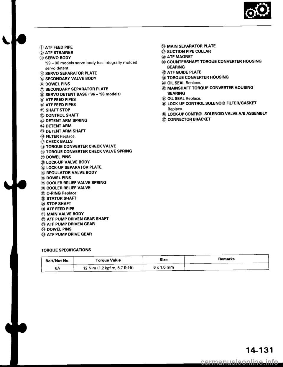
O ATF FEED PIPE
O ATF STRAINER
O SERVO BODY'99 - 00 models servo body has integrally molded
servo detent.
@ SERVO SEPARATOR PLATE
(' SECONDARY VALVE BODY
@ DOWEL P|NS
O SECONDARY SEPARATOR PLATE
@ SERVO DETENT BASE ('�96 -'98 models)
O ATF FEED PIPES
(D ATF FEED PIPES
O SHAFT STOP
@ CONTROL SHAFT
€D DETENT ARM SPRING
@ DETENT ARM
(9 DETENT ARM SHAFT
@ FILTER Replace.
(? CHECK BALLS
@ TOROUE CONVERTER CHECK VALVE
@ TOROUE CONVERTER CHECK VALVE SPRING
@ DOWEL PINS
@ LOCK.UP VALVE BODY
@ LOCK-UP SEPARATOR PLATE
@ REGULATOR VALVE BODY
@} DOWEL PINS
@ COOLER RELIEF VALVE SPRING
@ COOLER RELIEF VALVE
@ O-RING Replace.
@ STATOR SHAFT
@ STOP SHAFT
@ ATF FEED PIPE
@ MAIN VALVE BODY
@ ATF PUMP DRIVEN GEAR SHAFT
@ ATF PUMP DRIVEN GEAR
@ DOWEL PINS
65) ATF PUMP DRIVE GEAR
@ MAIN SEPARATOR PLATE
@ SUCTION PIPE COLLAR
@ ATF MAGNET
@ COUNTERSHAFT TOROUE CONVERTER HOUSING
BEARING
@ ATF GUIDE PLATE
@ ToRoUE CONVERTER HOUSING
@ OIL SEAL Replace.
@ MAINSHAFT TOROUE CONVERTER HOUSING
BEARING
@) olL SEAL Replace.
@ LOCK-UP CONTROL SOLENOID FILTER/GASKET
Reolace.
@ LOCK-UP CONIROL SOLENOID VALVE A/B ASSEMELY
@ CONNECTOR BRACKET
TOROUE SPECIFICANONS
Bolt/Nut No.Torque ValugSiz€Remarkg
12 N.m (1.2 kgf.m,8.7 lbnft)6x1,0mm
14-131
Page 814 of 2189
Torque Converter Housing/Valve Body
Removal
ATF FEEO PIP€
LOCK-UP VALVEBODY
PIN
6x1.0mm
LOCK-UP SEPARATORPLATE
REGULATORVALVE SODY
DOWEL PIN
COOLER RELIEF VAL
SERVO DETENTSTRAINER
SERVO EODY
SEPARATON
BASE
ATF FEEDPIPES
CONTROLSHAFT
DETENTARM SHAFT
DETENTARM
ATF FEED PIPE
6x1.0mm5 Eolts6x1.0mm3 Eolts
MAIN VALBODY
ATF PUMP
DRIVEN
VALVE BODY
PINGEAR SHAFT
ATF PUMP
MAIN SEPARAPLATE
SECONDARYSEPARATOR PLATE
NOTE: The illustration shows the '96 - 98 models, the '99 - 00 models do not have the servo detent base; the servo detentis integral with the servo body.
L
14-136
Page 823 of 2189

Regulator Valve Body
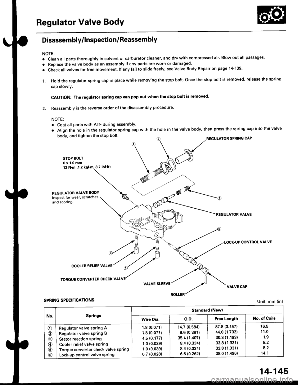
Disassembly/lnspection/Reassembly
NOTE:
. cleanall parts thoroughly in solvent or carburetor cleaner, and drywith compressed air. Blowoutall passages
. Replace the valve body as an assembly if any parts are worn or damaged.
. check allvalves for free movement. lf anyfail toslidetreely, see valve Body Repairon page 1+139.
1. Hold the regulator spring cap in place while removing the stop bolt. once the stop bolt is removed. release the spring
cap slowly.
CAUTION: The regulator 3pring cap can pop out when the stop boh is removod'
2. Reassembly is the reverse order ofths disassembly procedure.
NOTE:
o Coat all parts with ATF during assembly.
. Align the hole in the regulator spring cap with the hole in the valve body, then press the spring cap into the valve
body, and tighten the stop bolt.
STOP BOLT6x1.0mm12 N.m 11.28.7 tbf.lrl
^/^'ou*'oRsPRrNGcAP
*N@
REGULATOR VALVE
\=f -.-*
*fi /F { a-tLocK.uPcoNrRoLvALVE
cooLERRELlEFvALVr"r?
ry
roRouE coNvERrER cHEcKv ^LvE//
v ^r* "r**::f vi{LvE cAp
SPRING SPECIFICANONS
REGULATOR VALVE BODY
Inspect lor wear, scratches
and scorlng.
Unit: mm (in)
No,Springe
Standard (Now)
Wire Dia.o.D.Free LengrthNo. of Coils
o
o
@
@
@
Regulator valve sPring A
Regulator valve spring B
Stator reaction spring
Cooler relief valve spring
Torque converter check valve spring
Lock-up control valve sPring
1.8 {0.07'�r)
1.8 (0.071)
4.5 (0.177)
1.0 (0.039)
1.0 (0.039)
0.7 (0.028)
'r4.7 (0.584)
9.6 (0.381)
35.4 (1.407)
8.4 {0.334)
8.4 {0.334}
6.6 {0.262}
87.8 (3.457)
44.0 (1.732)
30.3 (1.193)
33.8 (1.331)
33.811.3311
38.0 {1.4961
11.0
1.9
8.2
a.2't 4.1
14-145
Page 827 of 2189

Inspection
a Clearance Measurement
NOTE: Lubricate all parts with ATF during assembly.
1, Remove the mainshaft bearing from the transmis-
sion housing (see Page 14-1741.
2. Assemble ths parts below on the mainshaft.
NOTE: Do not assemble the O-rings during inspec-
tlon.
LOCKNUTCONICAL SPRIIIG WASHER
SNAP RING
lST CLUTCH ASSEMBLY
TXRUST WASHER
1ST GEAR COLLAR
TRA SMISSIONHOUSII{G BEARING
THRUST WASHER
4TI{ GEAR COLLAR
2ND/4TH CLUTCHASSEMBLY
THRUST WASHER36.5 x 55 mmSelective part.
THBUST NEEDLEBEARING
2ND GEAR
AEABII{G
IHRUST NEEDLEBEARING
MAINSHAFT
3. Torque the mainshaft locknut to 29 N'm (3.0 kgf'm,
22 tbt,ftl.
NOTE: Mainshaft locknut has left-hand threads.
29 N'm t3.0 kgl'm, 22 lbt'ft)
Hold 2nd gear against the 2nd clutch' then measure
the clearance between 2nd gear and 3rd gear with a
feeler gauge.
NOTE: Take measurements in at least three places,
and use the av€rage as the actual clearance'
STANDARD: 0.05 - 0.13 mm 10.002 - 0.005 in)
THRUST WASHER,36.5 x 55 mm
(cont'd)
1+149