Page 1973 of 2189

How the Gircuit Works
All Except GX
Do not smoke while working on the fuel system.
Keep open flame away trom the work area. Drain
fuel only into an approved container.
A thermistor is mounted in the fuel tank unit. When
the thermistor is cool, its resistance is very high.
When the thermistor's temperature increases, its
resistance decreases. Fuel in the fuel tank transters
heat away lrom the thermistor fast enough to keep it
cool so the thermistor's resistance stays high and
lhe low fuel indicator light does not come on. When
the fuel level drops below the thermistor, the
thermistor's temoerature increases. Without the fuel
to cool it, the thermistor's resislance decreases,
allowing current to llow through the low fuel
indicator light and the thermistor to ground, and the
low fuel indicator light comes on.
Refer to the Service Manual (Section 23, Electrical)
for specific tests or troubleshooting procedures.
GX
The PCM turns on the low fuel indicator light when
the fuel level is low. The PCM will also blink the
indicator light when a problem is detected by the
fuel tank pressure sensor or the fuel tank
temperature sensor.
Refer to the Service Manual GX Supplement
(Section 11 , Fuel and Emissions) for specific tests
or troubleshooting procedures.
74-1
Page 1983 of 2189

A/T Gear Position Indicator (conrd)
- How the Circuit Works
With the ignition switch in ON (ll) or START (lll),
voltage is applied to the A,/T gear position indicator.
The A,/T gear position switch provides a ground for
each position. As an input is grounded, its indicator
light comes on. lf you select R, for example, ground
will be provided to the input of the A,/T gear position
indicato( and the R indicator will come on.
With the headlight switch in PARK or HEAD, voltage
is applied to the RED/BLK wire terminal. This
changes the indicator panel illumination from fixed
to controlled by the dash lights dimmer input
through the RED wire.
When the powertrain (all except '96-'98 CVT) or
transmission ('96198 CVT) control module (PCM or
TCM) detects an abnormality in the automatic
transmission control system, or when you request
diagnostic trouble codes through the service check
connector, the PCM or TCM will make the D4 (D for
CVT) indicator light blink.
Refer to the Service Manual (Section 14,
Automatic Transmission) for specific tests or
troubleshooting procedures.
\ia
89-2
Page 2006 of 2189

Headlights (cont'd)
- How the Circuit Works
Low Beams
With the headlight switch in HEAD and the dimmer
switch in LO, current tlows through the headlight
switch. fuse 21 . fuse 22. and the low beam
tilaments to ground, and the low beams come on.
High Beams
With the headlight switch in HEAD and the dimmer
switch in Hl, current flows through the headlight
switch, dimmer switch, fuses 4, 5, and the high
beam filaments to ground, and the high beams
come on.
Current also llows through the high beam indicator
light to ground. The high beam indicator comes on
to remind the driver that the high beams are on.
Flash-to-Pass
The flash feature works with the headlight switch in
OFF, PARK, or HEAD (low beams). When you move
the flash-to-pass switch to ON, current flows
through the switch, fuses 4 and 5, and the high
beam filaments to ground, and the high beams
flash. The high beam indicator also flashes during
the flash operation. The flash function has no effect
if the high beams are already on
Daytime Running Lights (Canada)
When you turn the ignition to ON (ll) with the
parking brake released, the daytime running lights
control unit supplies battery voltage at the
WHT/RED wire. This voltage is applied to the high
beam headlights through the daytime running lights
resistor. Each high beam headlight receives less
than battery voltage causing them to come on at
reduced brightness.
lf the parking brake is set, a ground signal is applied
to the daytime running lights control unit at the
RED/GRN wire. lf the parking brake is set when you
first turn the ignition switch to ON (ll), the high beam
headlights will remain off until you release the
parking brake. Once the high beam headlights are
on, setting the parking brake will not turn them ofi.
When low or high beam operation is requested,
battery voltage from the headlight switch is applied
to the daytime running light control unit via the RED
wire. The daytime running lights control unit then
turns off the headlights.
Refer to the Service Manual (Section 23, Electrical)
for specific tests or lroubleshootrng procedures.
110-14
Page 2122 of 2189

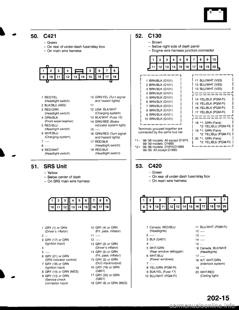
-50. c421
- Green- On rear of under-dash fuse/relay box- On main wire harness
I
l RED/YEL(Headlight switch)
2 BLIVBLU (ABS)
3 RED/GRN(Headlight switch)
4 GFIN/BLK(Front wiper/washer)
5 FED/BLU(Headlight swrtch)
6 WHT/BLU(Charging systern)
7
9 REDAVHT(Headlight switch)
10 GRN/YEL (Turn signaland hazard lights)
11
12 USA: BLKAVHT(Charging system)
13 BLKryVHT (Fuse 15)
14 GRN/RED (Brake
indicator system light)
16 GRN/RED (Turn signaland hazard lights)
17 BED/BLK(Headlight switch)
18 RED/BLK(Headlight switch)
52. C130
- Brown- Below right side ot dash panel- Engine wire harness junction connector
T---------"1
1 8RN/BLK (G101)
2 BRN/BLK (G101)
3 BRN/BLK (G101)
4 BRN/BLK (G101)
5 BRN/BLK (G101)
6 BRN/BLK (G101)
7 BRN/BLK (G101)
I BRN/BLK (G101)
9 BRN/BLK (G101)
10 BBN/BLK (G101)
L---------J
Terminals grouped together areconnected by the sarre bus bar.
*1= 96- 98 models: All except D16Y5'99-'00 models: D1685*2= 96-98 models: D16Y5/D1685'99- 00r All except D1685
11 BLUMHT (VSS)
12 BLU,ryVHT (VSS)
13 BLU,^/VHT (VSS)L_-_____--Jr---------'1
14 YEL/BLK (PGl\4-Fl)
15 YEL/BLK (PGr\4'Fr)
16 YEUBLK (PGI\4,FI)
17 YEUBLK (PGr\4,Fr)L______---JT----------118 *1: GRN (Fans)*2: YEUBLU (PGM-Fl)
19 *1: GRN (Fans).2: YEUBLU (PGM-Fl)
20 *1: GRN (Fans).2: YEUBLU (PGM-Fl)_______--J
51. SRS Unit
- Yellow- Below center oJ dash- On SRS marn wire harness
1 GFY (1) or GRN(Drivefs nflator)
2
3 GRY (17) or GRN(lgn tion input)
6 GRY (21) or GRN(SRS indicalor control)
7 GRY (18) or GRN(lgnition nput)
8 GBY (14) or GRN (MES)
9 GBY (13) of GRN(Service checkconnector input)
10 GRY (4) or GRN(Frt. pass. inflato4
11
13 GBY (2) or GRN(Drivefs nflator)
14 GBY (5) or GRN(Frt. pass. inflator)
15 GRY (3) or GRN(DLC input/output)
16 GRY (19) or GRN(G801)
17 GRY (20) or GRN(G801)
1B GRY (6) or GRN (MES)
13678
10Il12131415't7't8
53. C420
- Green- On rear of under-dash fuse/relay box- On main wire harness
1 Canadar RED/BLU(Headlights)
2
3 8LK (G401)
5 WHT/GRN(Rear window defogger)
6 WHT/BLU(Power windows)
7
8 YEL/GRN (PGM-FD
I BLK//EL (Fuse 17)
1O BLUAVHT (PGM,FI)
1 1 BLUMHT (PGI,4-FI)
14
16 Canada: BLKAVHT(Headlights)
18 A/Tr WHT/GRN(lnterlock system)
19
20 WHT/RED(Ceiling light)
202-15