Page 1815 of 2189
6. Install the new SRS unit.
NOTE: Do not reuse a torx bolt that has red
threads. Replace the bolt with a new one.
)
7.
TORX BOLTS9.8 N.m l'1.0 kg{.m, 7.2 lbf.ft}Use a Torx T30 bit.
Connect the SRS main harness l8P connector to the
SRS uniu push it into posjtion until it clicks.
Install the SRS unit covers (ri9ht and left). Make
sure the covers snap together in the middle.
8.
TORX BOLTS9.8 N.m 11.0 kgf.m, 7.2 lbf.ft)U3e . Torx T30 bit.
SRS MAIN HARNESS
)(l
9.
10.
't2.
Reconnect the driver's aibag 2P connector to the
cable reel 2P connector, then reinstall the access
panel on the steering wheel.
Reconnect the tront passenger's airbag connector
to the SRS main harness.
Reconnect the battery positive cable, then the nega
tive cable.
After installing the SRS unit, confirm proper system
operation: Turn the ignition switch ON (ll); the SRS
indicator light should come on for about six seconds
and then go oif.
11.
24-77
.-
Page 1817 of 2189

Contents
How to Use This Manual ICircuit Schematics (see Circuit Index)Fuse/Relaylnformation 6Ground-to-Componentslndex 6-6ComponentLocationPhotooraohs 201Conriector Views 202
Circuit Index
Accessory power socket 155Air conditionerAir delivery'96198 models 61'99-'00 models 61-2Blower controls'96198 models 60'99100 models 60-1Compressor controls 62Fans 63Anti-lock brake system (ABS) 44A/T gear position indicatorCVT 89All except CVT 89-1Automatic transmission controlsAll '96-'98 models except CVT and GX 39All '99100 models except CVT 39-8All GX models 39-8'96-'�98 CVT 39-4'99100 cw 39-12Back-up lightsCoupe and Sedan 110Hatchback l'10-1Brake lightsAll Coupes and'96-'98 Sedans 110-15'99-'00 Sedans 110-16Hatchback 110-17Brake system indicator light'96198 models 7'1'99100 models 71-1Ceiling light 114-3Charging system 22Condenser fan 63Console lights 114Cruise control 34Dash lights 114Daytime running lights 110- 13Engine coolant temperature gauge 81-1Fog lights 110-10Front parking lights 110-2Fuel gauge 81-1Fuse/relay boxUnder-dash 6Under-hood 6-4Underhood ABS 6-3Gauges 81Ground distribution 14Ground-to-Componentslndex 6-6Hazard warning lightsAll except '99100 Sedans 110-6'99100 Sedans 110-8Headlights 110-12Headlight switch 100Heater - See Air ConditionerHorn'96197 models 40'98 model 40-1'99100 models 40-2lgnition key reminder 73lgnition systemAll '96198 models except Dl685 20All '99100 models except D16Y5 with Mn 2O-2All D1685 engines 20-2'99-'00 D 16Y5 with M/T 20
lndicators 80Integrated control unit 70lnterlock systemAll except'96J98 CVT 138'96198CVT 138-1License plate lightsAll Coupes and '96-'98 Sedans I l0-3'99100 Sedans 1 10-4Hatchback 110-5Low fuel indicator light 74Moonrool'96197 models |22'98-'00 models 122-1Odometer 81Oil pressure indicator light 80-3Power distributionBattery to ignition switch, fuses, and relaysFuses to relays and components 10-2Power door locksAll models without keyless entry 130'96-'98 models with keyless entry 130-2'99100 models with keyless entry 130-12Power mirrorsWithout detogger 141With defogger '141-2
Power windows 120Programmed fuel injection system (PGNr-Fl)All '96-98 models except D1685 23All '99-'00 models except D16Y5with M/T and D1685 24All D1685 engines 25'99100 D16Y5 with M/T 23Radiator fan 63Rear window defogger'96-,98 models 64'99100 models 64-1Seat belt reminder 73Security system'96.'98 USA HX, LX, EX 133'96-'98 Canada EX, Si 133'99TOO USA HX, LX, EX, DX.V Si 133-4'99100 Canada EX, Si 133-4All CX and DX models 133-8Speedometer 81Starting systemA./T (All except Dl685) 21A"/r (D16Bs) 21-1Manualtransmission 21-2Slereo sound system 150Supplemental rastraint system (SRS) 47Tachometer 81TailliqhtsAllboupes and'96-'98 Sedans 110-3'99100 Sedans 1 10-4Hatchback 110-5Trunk light 114-3Turn signal lightsAll except'99100 Sedans 110-6'99-'00 Sedans 1 10-8Vehicle speed sensor (VSS) 33Wiper/washerFront 91Rear 92
10
Page 1828 of 2189

Five-Step Troubleshooting
L Verify The Complaint
Turn on all the components in the problem
circuil lo check the accuracy of the customer
complaint. Note the symptoms. Do not begin
disassembly or testing until you have
narrowed down the problem area.
2. Analyze The Schematic
Look up the schematic for the problem
circuit. Determine how the circuit is
supposed to work by tracing the current
paths lrom the power source through the
circuit components to ground. Also, trace
circuits that share wiring with the problem
circuit. The names of circuits that share the
same fuse, ground, or switch, and so on, are
referred to in each circuit schematic. Try to
operate any shared circuits you didn't check
in step 1 . lt the shared circuits work, the
shared wiring is OK, and the cause must be
in the wiring used only by the problem
circuit. lf several circuits fail at the same
time, the fuse or ground is a likely cause.
Based on the symptoms and your
understanding of the circuit's operation,
identify one or more possible causes.
3. lsolate The Problem By Testing The Circuit
Make circuit tests to check the diagnosis
you made in step 2. Keep in mind that a
logical, simple procedure is the key to
efficient troubleshooting. Test for the most
likely cause of failure first. Try to make tests
at points that are easily accessible.
4. Fix The Problem
Once the specific problem is identified,
make the repair. Be sure to use proper tools
and safe procedures.
5. Make Sure The Circuit Works
Turn on all components in the repaired
circuit in all modes to make sure you've
fixed the entire problem. ll the problem was
a blown fuse, be sure to test all of the
circuits on that fuse. Make sure no new
problems turn up and the original problem
does not recur.
Test Equipment
Most circuits include solid-state devices.
Test the voltages in these circuits only with
a 1o-megaohm or higher impedance digital
mUltimeter. Never use a test light or analog
meter on circuits that contain solid-state
devices. Damage to the devices may result.
Test Light and DVOM
On circuits without solid-state devices, use a
test light to check for voltage. A test light is
made up of a 12 volt bulb with a pair of leads
attached. After grounding one lead, touch the
other lead to various points along the circuit
where voltage should be present. The bulb
will go on if there is voltage at the point being
tested. lf you need to know how much
voltage is present, use a digital
volVohmmeter (DVOM).
Self-Powered Test Light and DVOM
Use a self-powered test light to check for
continuity. This tool is made up of a light bulb,
battery, and tlvo leads. To test it, touch the
leads together: the light should go on.
Use a self-powered test light only on an
unoowered circuit. First, disconnect the
battery, or remove the fuse that feeds the
circuit you are working on. Select two points
in the circuit belween which you want to
check continuity. Connecl one lead of the
self-powered test light to each point. lf there
is continuity, the test light's circuit will be
completed, and the light will go on.
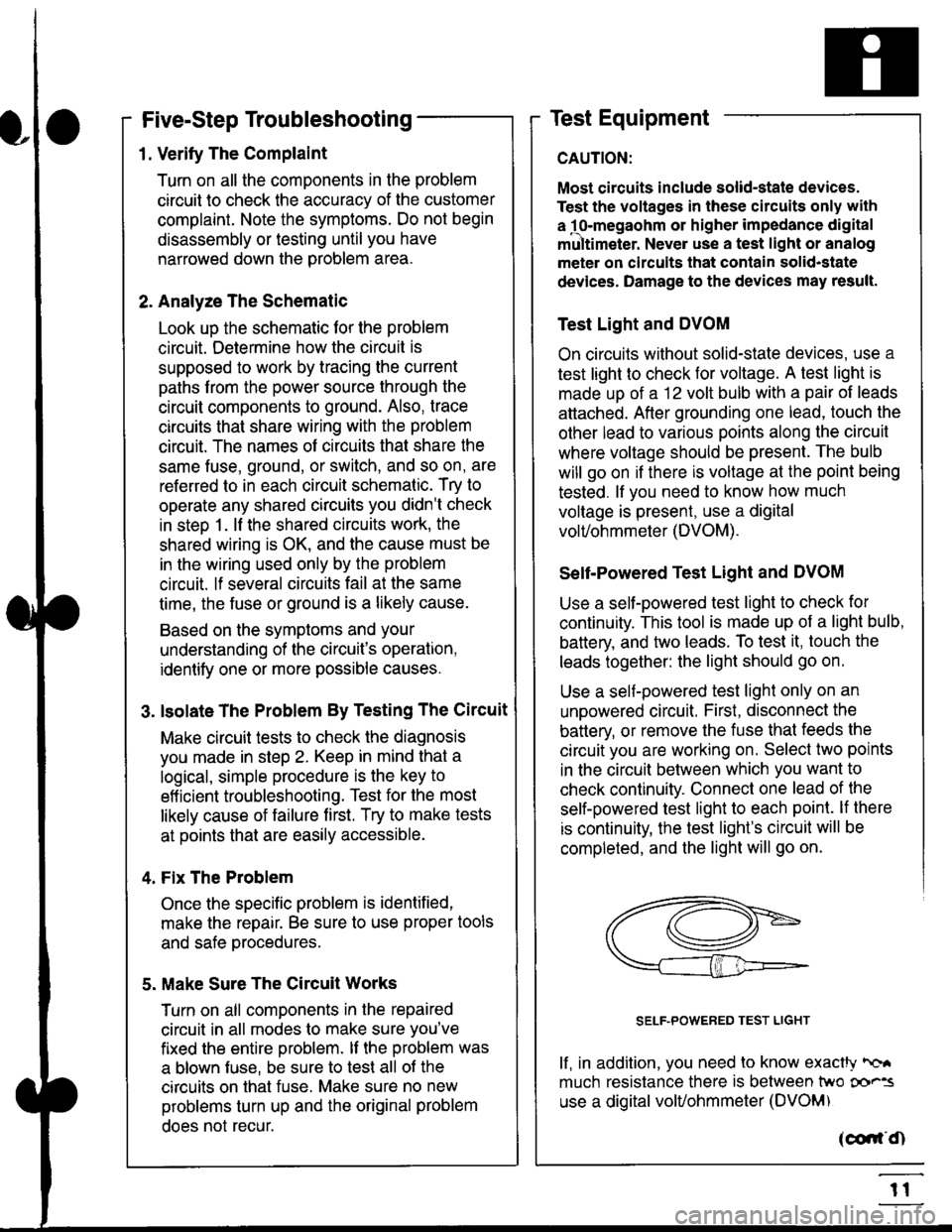
SELF-POWERED TEST LIGHT
lf, in addition, you need lo know exacW hc'.
much resistance there is between two oo'^=
use a digital volUohmmeter (DVOM)
acdrt'Cn
t1
Page 1835 of 2189

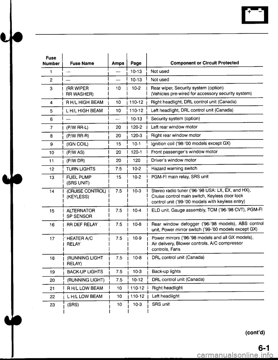
Fuse
NumberAmpsPageFuse Name
(RR WIPER
RR WASHER)
i R HiL HIGH BEAM | 10
L H/L HIGH BEAM
| (PAIV RR-L)
i (P/vv RR-R)
(rGN CO|L)
10I (P,^/V AS)
Component or Circuit Protected
Not used
Not used
Rear wiper, Security system (option)
(Vehicles pre-wired for accessory security system)
'10r 1n-2
I
| 1 10-12i Right headlight, DRL control unit (Canada)
Lett headlight, DRL control unit (Canada)
I ro-rsSecurity system (option)
| 120-2 | Left rear window motor
Right rear window motor
lgnition coil ('98-'00 models except GX)
| 120-1 | Front passenger's window motor
i (PiW DH)| 20 1 12O I Driver's window motor
TURN LIGHTSHazard warning switch
FUEL PUMP
(SRS UNIT)
PGM-FI main relav, SRS unit
(cRUrsE CoNTROL)
/KtrVt trSS\
Stereo radio tuner ('96-'98 USA: LX, EX, and HX),
Cruise control main switch, Keyless door lock
control unit ('99-'00 models with keyless entry)
15ALTERNATOR
SP SENSOR
l-a10-4I ELD unit, Gauge assembly, TCM (96-'98 CW, PGM-FI
16I RR DEF RELAY7.510-8I Rear window defogger ('96-'98 models), ABS control
I unit. Power mirror switch ('99-'00 models except GX)
i-HEATER r/C
I RELAY
Power mirrors ('96-98 models and all GX models),
Air delivery, Blower controls, AilC compressor
controls, Fans
I (RUNNING LIGHT
I RELAY)
1 7.5 1
tl
I DRL control unit (Canada)
i BACK-UP LTGHTSi Back-up lights
(RUNNING LIGHT)DRL control unit (Canada)
I R H/L LOW BEAM'10 l11o-12Right headlight
I L H/L LOW BEAM | 101110-12 | Left headlight
(cont'd)
(SRS)SRS unit
6-1
Page 1893 of 2189

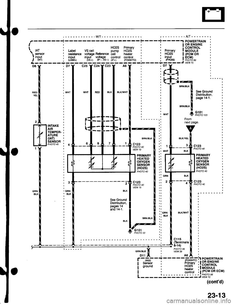
FED/YEL! il'Jlilli:Distribulon,
i
!aa
il-
"""r"a^ Itl
+9,1:1o,,,
Fromnext page.FI
t
H
INTAKE '
AIR ;TEMPER. .ATURE(rAr)SENSOR 'PHO|O 4s i 4
BRN/BLK
c123PHO|O 40vlEw 19c123
PRIMARYHEATEDOXYGENSENSOR(HO2S)
PRIMARYHEATEDOXYGENSENSOR(H02S)
-- -.-g c123,7 ,t1":.," I :: ' t---o} "",'"?",vtEw 19ErKl i:: ll [ .________i
leggtqe"d! ll:: I | :Distribution. I I ,; ll ll :
ffi31i1'1 ! lii i l:i ioty I er-rcrwr | :
:i*-! ! i
:i ! ! i
-a-- Glol:i I I :"uu,
--------t; igul,.[l :g.ili'""'"t i
11TI i
#?:?.'A6tr
i
F -tt-*i - I - - - -(-Po"GFil PowERTRAIN
i sdltGr i irimari' ' I oR ENGINE
! ;il;n i nciis' 'lcortnor
hear.r 'l MODULE| , haat.. .tMvuuLE
I ; ;;ii;r i | (PcM oR EcM)
I | ------riPHOfOS6L ------ - ------J vtae al
(cont'd)
. I OR ENGINE' HOzS Primary i CONTROLI fruzs Fflmary a c(JNIHor Label VS celt Dumo HOzS' ' , primary | MOOULE
i l"dqanc6 vohags Befe{ence bell . heater i : !-1029 | (p-Q!/| OB: red$snce voltag€ Beftrence c€ll heater ' : HOzS | (PCM OB: insJt input voltage control control ; ; inpul I ECM), (rABELt Ms+) tlP-.vs-) (rp+) (Po2sHrc) ; , l"Y_ j r;!J?.*----i---
i
-l "*
I'*l*'l
*l
i iillirlr I
:L+.1 l----,. (_l_.o-l
: I annar-x | :
: I I see Grourd
23-13
Page 1903 of 2189
PGM-FI (All '99-'q) Models except D16Y5 with M/T and D1685) (cont'd)
- Dl6Y7 Engine
ct6
(
k
GRN
GRN/ALK
II
)
-l.a
FUELTANKPRES-SURESENSOR(See S/M1
BLK
GFN/BLK
GNN/BLK
6
GAN/8LX
8
GFiI/BIK
tis3 :INTAKEAIRTEMPER-ATURE(|AT)SENSOR
PRIMARYHEATEDOXYGENSENSOR(HO2S)
c'123
c123
cs68PHOTO 103
c401
vtEw 40
ct31
vlEvt S9
FffiflH
{
r,Bi".'#
H
r{
t
f 5:o#'""'"n
rtrt
BLK
at
It
lFueltan* TP \lpr€asura Rg{grsncs ssnsor ECT IAT Primary IF€nsor inpJt voltago input sensor input sensor inpul HO2S inout I| (rt^xn Naca Crpsr lscn - -- 1-ran -- -(p,ioi3i-- ,L------- -----J
BLKT^YEL
clt5(Ierminals 8-14)
vlEw38
contaol
24-8
Page 1905 of 2189
PGM-FI (All '9S"00 Models except D16Y5 with M/T and D1685) (cont'd)
- Dl6Y8/816A2 Engines
c123PHO|O 133
)
t
II
r
k
'l
ir
c27
3 crsoI (Termlnals
ll 18-20)
li#?t?,"
It
ll
I ".r,".*ll
lt
ll
I
lt
lL___3
H'I
t
I
I
I Rrol tankipressure Fobrsnco: ssnsot inDul volt4€| (Pr^No 0ccaL-- --- - -*'I
:*I-.
;iH$ffi1
l-Flitii!
lJri li::#'":l
"oil ??$j
"rt
*tinr+- l+-
*'.,9s,g';,, f
-:i*<'lrp !
-I$"";*", o"",".,. I"rnLi':______I
ALK
INTAKEAIRTEMPER.ATURE(rAr)SENSORPHO|O 15
PRIMARYHEATEDOXYGENSENSOR(H02S)PHOTO 13iF}$iH
:{
F#-H
{
c123PHOTO 133
LT GFII
2
ORN/ALX
c1r5(Iermlnalr8-14)PHOfO 16
I
I
I
I
24-10
Page 1914 of 2189
-.t POWERTRAIN
lcoNTRoL
Fuel I MODULE
\. . -,.^-- p{sssure
I llglllTP-. . sansor sensor .s€nsor i;ir*,o; sensor_rnpul input input input :I nFa (PF2) GcD i|An IrL------ --------Jc13 I' c14Y c26
FUELTEMPERATURESENSOR
Fromfacingpage.
v
!
_l
Fromnenpage.
vi
GFN/BLK lI
i
EG-f
flltur'ffi
,{J
ENGINECOOLANTTEMPERATURE(Ecr)SENSOR
INTAKEAIRTEMPERATURE(rAr)SENSOR
c't 15(ferminals &14)
vtEw 38
(cont'd)
25-7