Page 630 of 2189
Transmission Assembly
Removal(cont'd)
14. Remove the driveshafts and the intermediate shaft(see section 16).
NOTE: Coat all precision the finished surfaces with
clean engine oil or grease. Tie plastic bags over the
driveshaft ends,
Remove the bolt, then disconnect the change elden-
sion.
Remove the clip and the spring pin, then disconnectthe change rod.
8x22mmSPRING PINCLIP Replace.
15.
13-50
17. Remove the front and the rear engine stiffensrs.
18. Remove the clutch cover.
CLUTCH COVER
6x1.0mm12 N.m (1.2 kg{.m,9 tbf.ftl
x 'l .25 mm
tJ
24 N.m {2.4 kgt m,17 rbt ftl
Page 632 of 2189

Transmission Assembly
lnstallation
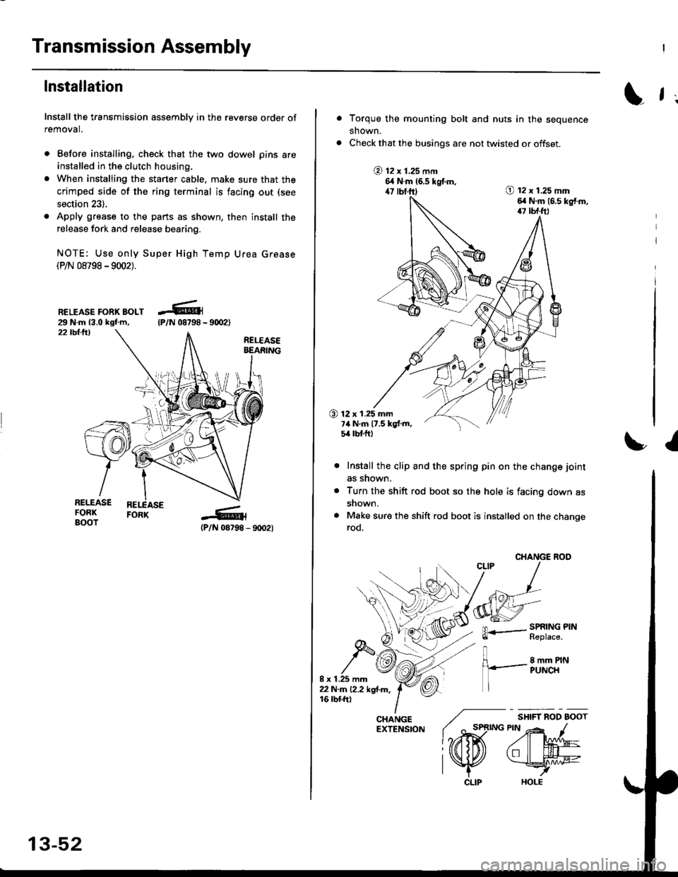
Install the transmission assembly in the reverse order of
removal.
. Before installing, check that the two dowel pins are
installed in the clutch housing.
. When installing the starter cable. make sure that the
crimped side of the ring terminal is facing out (see
section 23).
. Apply grease to the parts as shown, then install the
release fork and release bearing.
NOTE; Use only Super High Temp Urea Grease(P/N 08798 -9002).
RELEASE FORK BOLT29 N.m 13.0 kgf.m,22 tbllrl
(P/N 08798 - 9rD2l
-R1
tP/N 08798 -
13-52
CLIP
L f ;
Torque the mounting bolt and nuts in the sequence
shown.
Check that the busings are not twisted or offset.
@ t2 x 1.25 mm6,t N.m 16.5 kgtm,47 lbf.ft)O t2 x 1.25 mm6,r N.m (6.s kg{.m,17 tbf.ft)
O 12 x 1.25 mm7ilNm17.5kgf.m,5it lbt ft)
I
Install the alip and the spring pin on the change joint
as snown.
Turn the shift rod boot so the hole is facing down as
snown.
Make sure the shift rod boot is installed on the changerod.
CHANGE ROO
FL.- SPRING PINll heptace,
8 mm PINPUNCH
/ "*,*
lo,iD(
CHANGE ./EXTENSfoN ( ^ st
l?rffi
l\K
Page 633 of 2189
. Apply grease to the slave cylinder push rod.
NOTE: Use only Super High Temp Urea Grease
(P/N 08798 - 9002).
6x1.0mm9.8 N'm (1.0 kgl m,
7.2 tbl.ft)
-6,4- 9m2)
Refillthe transmission with oil (see page 13-47).
Connect the positive (+) cable first, then the negative
( - ) cable to the battery.
Check the clutch oPeration.
Shift the transmission, and check for smooth opera-
tion.
Check the front wheel alignment (see section 181.
(P/N 08798
8 x 1 .25 mm22N.n 12.2 kgl'm,16 tbf.ftl
a
a
a
a
Page 634 of 2189
lllustrated Index
t
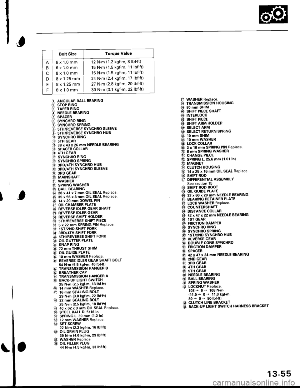
Refer to the drawing below for transmission disassembly/reassembly.
Clean all the parts thoroughly in solvent and dry with compressed air.
I Luoricate att the pans with oil before reassembly.
NOTE:
. This transmission uses no gaskets between the majorhousings; use liquid gasket (P/N 08718-0001 or08718-0003)
(see page '13-93).
. Always clean the magnet @ whenever the transmission housing is disassembled.
. Inspect all the bearings for wear and operation.
?-c
\I
ir 6d
a h Plt tia.fl
) K1T\A
l,l 1r
@rt? u
L6q
i"\^Br 'u
t@)
E,M A
#&f
o-*ffiX,
@
I
R
h"ii
'F@
,
€D
13-54
Page 635 of 2189

Bolt SizeTorque Value
cn
E
F
6x1.0mm
6x1.0mm
8 x 1.0 mm
8 x '1.25 mm
8 x 1.25 mm
8 x 1,0 mm
12 N.m (1.2 kgnm, 8 lbf'ft)
15 N.m (1.5 kgf'm, 11 lbf ft)
15 N.m (l.5 kgf.m, 11 lbift)
24 N'm (2.4 kgim, 17 lbift)
27 N.m (2.8 kgf.m,20 lbf'ft)
30 N.m (3.1 ksf m. 22 lbift)
5i WASHER Replace.6 TRANSMrssioN HouslNG!9 80 mm SHIM@ SHIFT PIECE SHAFT(6' INTERLOCK@ sHrFr PECE6} SHIFT ARM HOLDER@ seucr nnrvtI9 SELECT RETURN SPRING
@ 10 mm SHIM6, 10 mm WASHER@ LOCK COLLARi6sl 3 x l5 mm SPRING PIN Replace.t0 8 mm SPRING WASHERA) CHANGE PIECEll SPRING L.25.6 mm (1.01 in)'' MAGNET?4) CLUTCH HOUSINGta. 14 x 25 x 16 mm OIL SEAL Replace.A sHrFT BooO D|FFERENT|aL ASSEMBLYSee section 15iIO SHIFT ROD BOOT6 OIL GUIDE PLATE@ 33 x 60 x 20 mm NEEDLE BEASINGO BEARING RETAINER PLATElD LocK WASHER Replace..0 couNTERSHAFIA DISTANCE COLLAR6 & x 4I x 22 mm NEEDLE BEARING6. 1sr GEAR@ FRICTION DAMPERO SYNCHRO RING.d SYNCHRO SPRING@ 1ST/2ND SYNCHRO HUB..9i. REVERSE GEARC) DOUBLE CONE SYNCHROO FRICTION DAMPERS SPACER6 T2 x TI x 24 mm NEEDLE BEARING(!' 2ND GEAR61 3RD GEARiD 4TH GEAR@ 5TH GEAR(O NEEDLE BEARING(10 BALL BEARING@ SPRING WASHERf,o LoCKNUT Replace.108 - 0- 108 N'm111.0- 0* 11.0 kgf m,80* 0- 80lbI.ft)IO CLUTCH LINE BRACKET.d BACK.UP LTGHT SWITCH HARNESS BRACKET
:!, ANGULAR BALL BEABING:2, STOP RING:3] TAPER RING..-I NEEOLE BEARINGl!-- SPACERO SYNCHRO RING? SYNCHRO SPRINGE 5TH/REVERSE SYNCHRO SLEEVE...] sTH/REVERSE SYNCHRO HUB
O SYNCHBO EING.11-r sTH GEAR1A 38 x 43 x 26 mm NEEDLE BEARINGI13) SPACER COLLAR[!] /ITH GEAR.T5) SYNCHRO RING
O SYNCHRO SPRING17 3RD/4TH SYNCHRO HUB
O 3RD/4TH sYNcHRo SLEEVE
ii9 38D GEAR8I MAINSHAFT2i WASHERA SPRING WASH€R?I BALL BEARING.a4, 28 x 41 x 7 mm OIL SEAL Replace..2i 35 x 56 x 8 mm OIL SEAL Replace.t-t 14 x 20 mm DowEL PIN
.'] OIL CHAMBER PLATE
O REVERSE IDLER GEAR SHAFT.iI.., REVERSE IDLER GEAR'd REVERSE SHIFI HOLDERait srH/REVERSE sHIFT PIECE'34 5 x 22 mm SPRING PIN Replace.3' 1ST/2ND SHIFT FORK,34' 3RD/4TH SHIFT FORKi9t) srH/nevense sstrr ronx33 OIL GUTTER PLATE!' SNAP RING3d 72 mm THRUST SHIM
@ OIL GUIDE PLATE4t 10 mm WASHER Replaceti REVERSE TDLER GEAR SHAFT BoLT54 N.m {5.5 kgf m, 40lbIft)4N TBANSMISSION HANGER B43] BREATHER CAPA,J TRANSMISSION HANGER AIT' BACK-UP LIGHT SWITCH
I
25 N.m {2.5 kgl.m, 18lblftl14 mm WASHER RePlaceaO 14 mmtt 16 mm16 mm SEALING BOLT29 N.m (3.0 kgf m,22 lbf ft):4s) 32 mm SEALING BoLT25 N m 12.5 kgl m, 18 lbl'ft)40 x 62 x I mm OIL SEAL ReplaceSTEEL BALL D.5/15 iNSPRING L. 30 mm {1.2 in)12 mm WASHER Replace.SET SCREW22 N.m {2.2 kg{ m, 16 lbl ftlOIL DRAIN PLUG39 N.m {4.0 kgf m, 29lbtftlWASHER Replace.OIL FILLER PLUG4,t N.m {4.5 kgl m, 33 lblftl
.!rl00
@l
13-55
Page 637 of 2189

Reverse Shift Holder,
Reverse ldler Gear
Separate the transmission housing from the clutch
housing, and wipe it clean of the sealant.
Remove the 72 mm thrust shim and the oil guide
plate from the transmission housing
72fifiTHRUST SHIM
TRANSMISSION HOUSING
Remove the 16 mm sealing bolt and the oll gutter
plate.
OIL GUTTER PLATE
fi
1.
Clearance Inspection
Measure the clearance between the reverse shift
holder and the 5th/reverse shift piece pin
Standard:
Revsrs. Sids: 0.05 - 0./t5 mm {0'002 - 0.018 in}
5th Side: 0.4 - 0.9 mm (0.02 - 0.0'l in)
sTH/REVERSE SHIFT PIECE PIN
lf the clearance are not within the standard, mea-
sure the width of the grooves in the reverse shift
holder.
Standard:
Rsvers€ Side: 7.05 - 7.25 mm (0'278 - 0.285 in)
5th Sid6: 7.,1- 7.7 mm (0.29 - 0 30 inl
REVERSE SIDE
lf ths width of the grooves are not within the
standard, replace the reverse shift holder with a
new one.
lf the width of the grooves are within the stan-
dard, replace the sth/reverse shift piece with a
new one {cont'd)
13-57
Page 638 of 2189
Reverse Shift Holder, Reverse ldler Gear
Clearance Inspection (cont'dl
3. Measure the clearance between the reverse
gear and the reverse shift holder.
Standard: 0.5 - 1.0 mm 10.02 - 0.04 inl
Service Limit: 1.8 mm (0.07 inl
id ler
lf the clearance is more than the service limit. mea,
sure the width of the reverse shift holder.
Standard: 13.0 - 13.3 mm (0.512 - 0.524 in)
lf the width is not within the standard, replace
the reverse shift holder with a new one.
lf the width is within the standard, replace the
reverse idler gear with a new one.
REVERSE SHIFT HOLDER
13-58
Removal
1. Remove the reverse shift holder.
Remove the reverse idler gear and the reverse idlergear shaft.
REVERSE SHIFT HOLDEB
REVERSEIDLER
Page 639 of 2189

Change Holder AssemblY
,Glearance InsPection
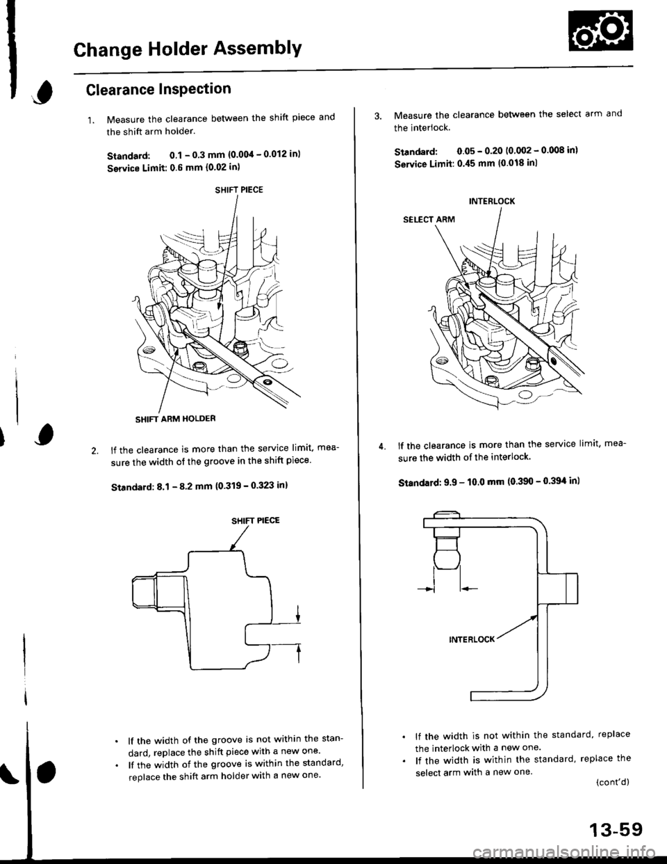
1.Measure the clearance between the shift piece and
the shift arm holder.
Standard: 0.1 - 0.3 mm {0.004 - 0.012 in)
service Limit: 0.6 mm {0.02 in)
lf the clearance is more than the service limit, mea-
sure the width of the groove in the shift piece'
Standard: 8.1 - 8 2 mm {0'319 - 0.323 in}
lf the width of the groove is not within the stan-
dard, replace the shift piece with a new one'
lf the width of the groove is within the standard,
replace the shift arm holder with a new one'
SHIFT PIECE
SHIFT ARM HOLDER
SHIFT PIECE
4.
3. Measure the clearance between the select arm and
the interlock.
Standard: 0.05 - 0.20 10 002 - 0.008 inl
Service Limit:0.45 mm (0.018 inl
lf the clearance is more than the service limit, mea-
sure the width of the interlock.
Standatd: 9.9 - 10.0 mm (0.390 - 0.39't in)
lf the width is not within the standard, replace
the interlock with a new one.
lf the width is within the standard, replace the
select arm with a new one.(cont'd)
INTERLOCK
13-59