Page 198 of 2189
Engine Block
Speciaf Tools ..........." 7-2
lllustlated Index ...................."..'.......... 7-3
Flywheel and Drive Plate
Repf acement """'.' 7-7
Connecting Rod and Crankshaft
End Play ..........."....7-8
Main Bearings
Clearance ............... 7-9
Selection ................7-10
Connecting Rod Bearings
clearance ....'.......... 7-11
Selection ................ 7-11
Pistons and Crankshaft
Removaf ................. 7 -12
Crankshaft
Inspection ."".........7-14
Pistons
Inspection ......"'.....7-15
fnstaffation .............7-23
Cylinder Block
lnspec'tion ..............7-16
Bore Honing ..........7-17
Piston Pins
Removal ...,...........'.7-17
lnstallation .............7-18
Inspection .'............7-19
Connecting Rods
Selection ................7-18
Piston Rings
End Gap ..........".."' 7'2O
Repfacement .........7-2O
Ring-to-Groove Clearance ...........'.'. 7 -21
Afignment .......""'.. 7'21
Crankshaft Oil Seal
fnstaffation .............7-22
Crankshaft
fnstaffation ..-.-..'.".' 7'23
Oil Pan
lnstallation .............7-26
Oil Seals
fnstaffation ....""""' 7-29
r-f
Page 200 of 2189
lllustrated Index
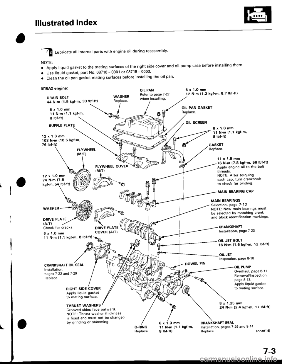
I runricate att internal parts with engine oil during reassembly'
NOTE:
o Apply liquid gaskettothe mating surfaces ofthe right side cover and oil pumpcase before installingthem'
. Use liquid gasket, part No 08718-0001 or08718-0003'
. Clean the oil pan gasket mating surfaces betore installing the oil pan
81642 engine:
DRAIN BOLT44 N,m {4.5 kgf'm,33 lbt'ft)
6 x 1.0 mm'11 N.m (1.1 kgI'm,
I tbl.ft)
OIL PANReter to page 7 27when installing.
6 r 1.O mm12 N.m t1.2 kgl'm, 8 7 lbf'lt)
OIL PAN GASKET
BUFFLE PLA
12 x 1.0 mm103 N.m {10.5 kgf'm,
76 tbr.ft)
6 x 1.0 mm11 N.m (1 .1 kgf.m,
8 tbI.fr)
GASKETReplace.FLYWHEEL(M/TI
12 x 1.0 mm
74 N.m (7.5
kof.m, 54 lbf'ft)
1^c{Eb\%^ t*^
*o"rr^--(Wffi
oa*,trto2,.w
FLYWHEEL COVER
IM/T)
DRIVE PLATECOVER (AiT)
11 x 1.5 mm76 N.m (7.9 kgf'm, 56 lbf'ft)
Apply engine oil to the bolt
threads.NOTE: After torqurngeach cap, turn crankshaft
to check for binding.
MAIN EEARING CAP
MAIN BEARINGSSelection, page 7_10
NOTE: New main bearings musl
be selected bY matching crank
and block identification markrngs
CRANKSHAFTInstallation, Page 7'23
OIL JET BOLT16 N.m 11.6 kgf'm, 12 lbl'ft)
OIL JETInspection, Page 8_10
Check for cracks
6x1.0mm11 N.m {1.1 kgf'm, I lbf'ft}
CRANKSHAFT OIL SEAL
Installation,pagesl 22 andl 29
Replace-
DOWEL PINOIL PUMPOverhaul, page 8-'l1Removal/lnspection,page 8-13.Apply liquid gasket
to mating surlace.RIGHT SIDE COVERApply liquid gasket
to mating surface.
THRUST WASHERS8 x 1.25 mm24 N.m {2.4 kgf.m, 17 lbf'ft)Grooved sides face outward
NOTE: Thrusr washer thickness
is tixed and must not be changed
by grinding or shimming
O-RINGReplace
CRANKSHAFT SEAL11 N.m {1.1 kgf'm, lnstallation, pages 7'29 and I 14
a lbt.ltl Heplace. (cont'd)
d#*
Page 201 of 2189

lllustrated Index
(cont'dl
I Luoricate att internal parts with engine oil during reassembly.
NOTE:
' Apply liquid gasket to the mating surfaces ofthe rightside coverand oil pumpcase before installingthem.. Use liquid gasket, part No. 08718 - 0001 or 087,18 _ OOO3.. Clean the oil pan gasket mating surfaces before installing it.
D16Y7 engine:6 x 1.0 mm12 N.m (1.2 kgt.m.8.7 tbf.tr)DRAIN BOLT44 N.m {4.5 kgt.m.33 tbt.ttl
,(
I
I
OIL PAN GASKETFLYWHEEL COVERIM/T)6x 1.0 mm12 N.m ('l .2 kgt.m, 8.7 tbt.trl
OIL PANRefer to page 7-27
Apply liquid gasker tothese points.
Replace.
WASHERReplace.12 x '1.0 mm118 N.m{12.0 kgt.m, 87 tbf.tr}
11 x 1.5 mm51 N.m15.2 kgl.m,38lbtftl
Apply engine oilto the boltthreads.NOTE: After torquingeach cap, turn the crankshaftto check for binding.
MAIN BEARINGSSelection, page 7-10
MAIN BEARING CAP
CRANKSHAFTInstallation, page 7 23
NOTE: New main bearings mustbe selected by matching crankand block identification markings.
6 r 1.0 mm11 N.m {1.1
6 x 1.0 mm11 N.m 11.1
ksI.m, 8 lbt.ft)
OIL SCREEN
kgt.m, 8 lbf.trl
Check for cracks.
CRANKSHAFT OIL SEALInstallation,pages 1 22 a^d 7-29
\:eprace'
GASKETReplace.
6 x 1.O mm11 N.m {1.1 kgt.m,8 rbt.frl
RIGHT SIDE COVERApply liquid gasker1o matrng surface,
OIL PUMPOverhaul, page 8-12Bemoval/lnspection,page 8-13
DOWEL PIN
WASHERSGrooved sides face outward.NOTE: Thrust washer thicknessis fixed and must not be changedby grinding or shimming.
CRANKSHAFT SEAL
l.j"Ji:l"^ pages z.2e --.S)
Replace.
6 x 1.0 mm11 N.m {1.18 tbt.fr)
7-4
BREATHING PORT COVERMOUNT BOLTS6 x 1.0 mm11 N.m {1.1 kgt.m, 8 tbf.fr}Apply liquid gasker tothe boh threads.
DOWEL PIN
Page 203 of 2189

lllustrated Index
(cont'd)
NOTE: New rod bearings must be selected by matching connecting rod assembly and crankshaft(see page 7,11).identification markings
Lubricate all internal parts with engine oil duringreassembtv.
PISTON INSTALLATION DIRECTION:
EXHAUST
4\/=\6\z\
\e/!rqrf/
INTAKE
PISTON RINGSReplacement. page 7-20Measurement, pages 7 20 andj-21Alignment, page 7-21
PISTON PINRemoval, page 7,17Installation, page 7-18Inspection, page 7,19
CONNECTING RODEnd play, page 7-8Selection, page 7,18
CONNECTING RODBEARINGSClearance, page 7 11Selection, page 7-11
CONNECTING ROD BEARING CAPInstallation, page 7-23NOTE: lnstall caps so thebearing recess is on thesame side as the recessin the rod.
PISTONInspectron, page 7-15NOTE: Betore removing the piston, inspect thetop of the cylinder bore for carbon build-up orridge. Bemove ridge if necessary, page 7-13
ENGINE BLOCKCylinder bore inspection, page 7-16Warpage inspection, page 7,'16Cylinder bore honing, page 7,17
Inspect top of each cylinder borefor carbon build-up or ridgebefore removing piston.Remove ridge if necessary, page 7-13
CONNECTING ROD CAP NUT816A2 €ngin6:9 x 0.75 mm{0 N.m (4.1 kgt m, 30 tbf.ftlD16Y5, Dl6Y7. D16Y8 engines:8 x 0.75 mm3l N.m {3.2 kg{.m,23 tbt.fr)Apply engine oiltothe bolt threads.NOTE: After torquing each bearingcap, rotate crankshaft tocheck for binding.
7-6
Page 207 of 2189

Main Bearing
Selection
CAUTION: lf the codes are indecipherable because of anaccumulation of dirt and dust, do not scrub them with a
wire brush or scraper. Clean them only with solvent ol
deiergent.
Crankshaft Bore Code Location
81642 engine:
Letters have been stamped on the end of the block as acode for the size of each of the 5 main journal bores.
Use them, and the numbers or bars stamped on the
crank {codes for main journal size), to choose the correct
beaflngs.
Main JournalCode Locations {Nombers or Barc)
Eearing ldentificationColor code rson lhe edge ofthe bear ng.Larger crank bore
acD
-----------""' Smallerbeanngtlhrcker)
9""1B':""
Alack
Black
Alue
7-10
\
D16Y5, D16Y7, D16Y8 engines:
Letters have been stamped on the end of the block as acode for the size of each of the 5 main journal bores.
Use them, and the numbers stamped on the crankshaft(codes for main journal size), to choose the correct bear-
Ings.
Main Journal Code Location (Numbers)
\
Color codeon theedge ofthe bearing-
Ldrger crank bore
Smaller bea ng {th'cker)
lr-l
t#lt+,tlf l 4 tlf '- 't
Smaller Smallermaan bearingjournal {thicker)
RedPinkGreen
PinkGreenBrown
GreenBrownBlack
GreenBrownBlackElue
I
Bearing ldentification
BcD
Page 211 of 2189
Crankshaft
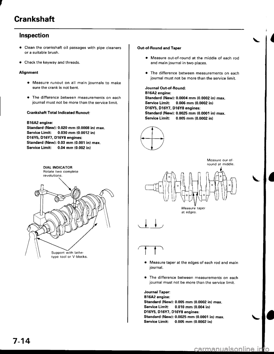
Inspection
. Clean the crankshaft oil passages with pipe cleaners
or a suitable brush.
. Check the keyway and threads.
Alignment
. Measure runout on all main journals to make
sure the crank is not bent.
. The difference between measurements on eachjournal must not be more than the service limit.
Crankshaft Total Indicated Runout:
Bl6A2 engine:
Standard (Newl: 0.020 mm {0.0008 in} max.
Service Limit: 0.030 mm {0.0012 inl
D16Y5, D15Y7, D15Y8 engines:
Standsrd {New): 0.03 mm (0.001 in} max.
Service Limit; 0.0i1 mm 10.002 in)
Support with lathetype tool or V blocks.
7-14
Out-of-Round and Tapet
. Measure out-of-round at the middle of each rod
and main journal in two places.
a The difference between measurements on eachjournal must not be more than the service limit.
Joulnal Out-of-Round:
81642 engine:
Standard (New): 0.0004 mm {0.0002 in) max.
Service Limit: 0.006 mm {0.0002 in)
Dr6Y5, Dl6Y7, D16Y8 engines:
Standard (Newl: 0.0025 mm (0.0001 inl max.
Service Limh: 0.005 mm (0.0002 inl
round at middle.
. Measure taper at the edges of each rod and mainjournal.
. The difference between measurements on eachjournal must not be more than the service limit.
JournalTaDer:
B16A2 ongine:
Standard lNewl: 0.005 mm (0.0002 inl max.
Service Limit: 0.010 mm (0.00i1 inl
D16Y5, D16Y7, Dl6YB engines:
Standard (New): 0.0025 mm {0.0001 in) max.
Service Limit: 0.005 mm (0.0002 in)
\
Page 212 of 2189
Pistons
Inspection
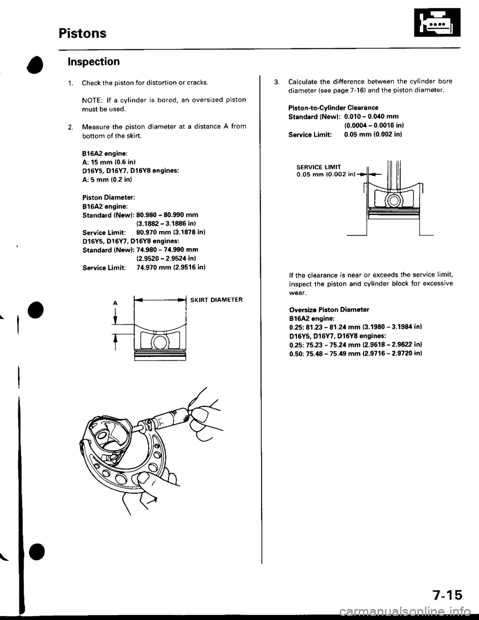
1.Check the piston for distortion or cracks,
NOTE: lf a cylinder is bored. an oversized piston
must be used.
Measure the piston diameter at a distance A from
bottom of the skirt.
816A2 engino:
A: 15 mm 10.6 in)
D16Y5, D16Y7, D16Y8 engines:
A: 5 mm (0.2 inl
Piston Diameter:
816A2 engine:
Standard lNewl: 80.980 - 80.990 mm
13.1882 - 3.1886 in)
Service Limit: 80.970 mm (3.1878 in)
D16Y5, D16Y7, D16Y8 engines:
Standard {New): 7,f.980 - 7i1.990 mm
|.2.9520 - 2.9521in!
Service Limit: 74.970 mm {2.9516 inl
SKIRT DIAMETER
57-1
3. Calculate the difference between the cylinder bore
diameter (see page 7-16) and the piston diameter.
Piston-to-Cylinder Clsarance
Standard lNewl: 0.010 - 0.0,10 mm
(0.0004 - 0.0016 inl
Servico Limit: 0.05 mm {0.002 in}
lf the clearance is near or exceeds the service limit,
inspect the piston and cylinder block for excessive
wear.
Oversizo Piston Diametor
816A2 ongine:
0.25t 81.23 - 81.21 mm (3.1980 - 3.1984 inl
D16Y5. D16Y7, D16Y8 engines:
O.25t 75.23 - 75.21 mm (2.9618 - 2.9622 in)
0.50: 75.i18 - 75.49 mm {2.9716 - 2.9720 in}
Page 213 of 2189
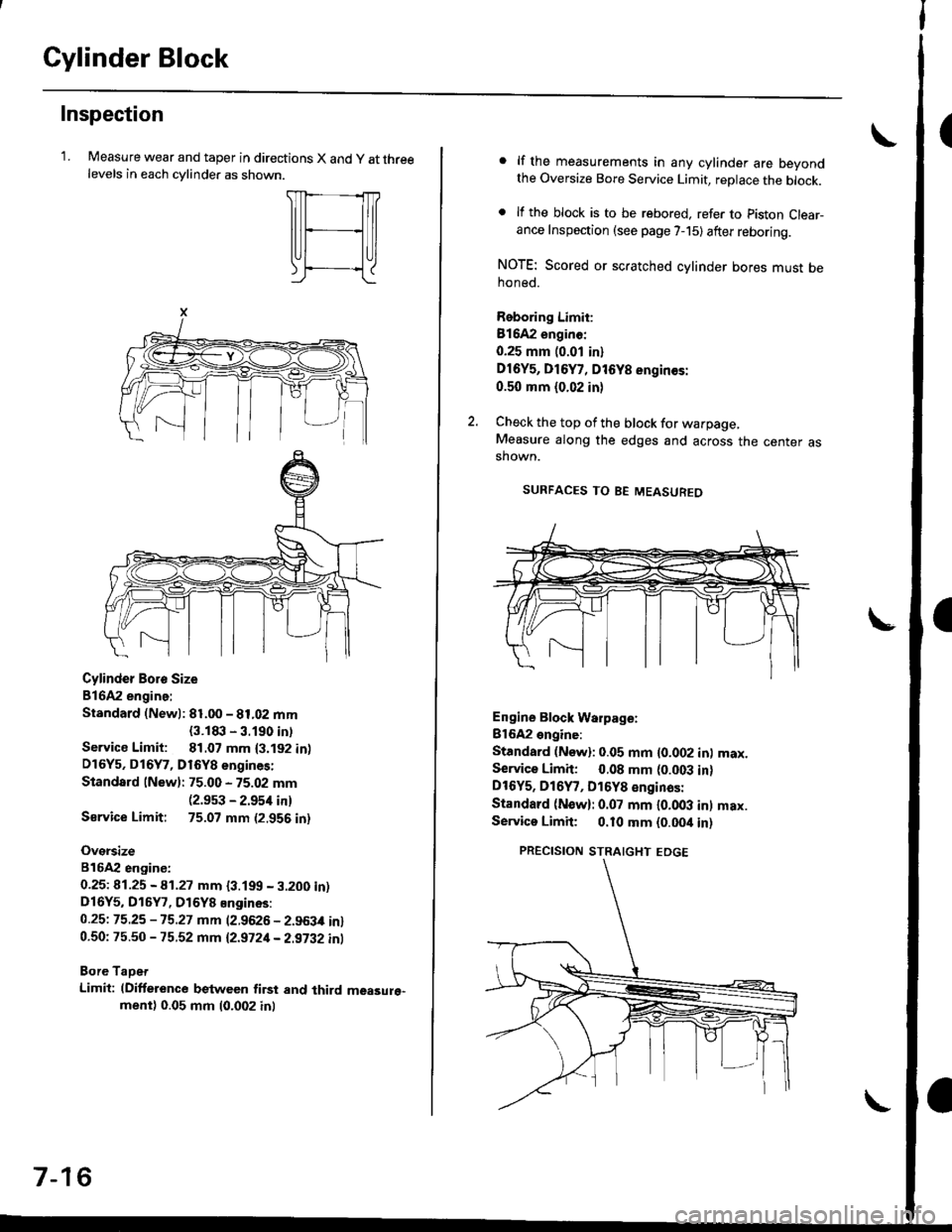
Cylinder Block
Inspection
'LMeasure wear and taper in directions X and y at threelevels in each cvlinder as shown.
Cylinder Boro Size
816A2 engine:
Standard (Newl: 81.00 - 81.02 mm
{3.1t|:l - 3.190 intService Limit: 81.07 mm {3.192 in)D16Y5, D16Y7, D16Y8 engines:
Standard lNew): 75.00 - 75.02 mm(2.9s3 - 2.954 in)
Sarvice Limit: 75.07 mm (2.956 in)
Oversize
816A2 engiDe:
0.25t 41.25 - A1.27 mm {3.199 - 3.200 in)D16Y5, D16Y7, D16Y8 Engines:
0.25t 75.25 -15.27 mm (2.9626 - 2.963,0 in)0.50: 75.50 - 75.52 mm 12.9721- 2.9i32 inl
Bore TaDet
Limit: (Difference between first and third measure"ment) 0.05 mm (0.002 inl
7-16
lf the measurements in any cylinder are beyondthe Oversize Bore Service Limit, replace the block.
lf the block is to be rebored. refer to piston Clear-ance Inspection (see page 7-15) after reboring.
NOTE: Scored or scratched cylinder bores must behoned.
Reboring Limit:
Bl642 enginc:
0.25 mm (0.01 in)
Dl6Y5, D16Y7, D16Y8 engin€s:
0.50 mm (0.02 in)
Check the top of the block for warpage,Measure along the edges and across the center asshown.
SURFACES TO BE MEASUREO
Engine Block Warpage:
Bl6A2 engine:
Standard (Now): 0.05 mm {0.002 inl max.Service Limh: 0.08 mm (0.003 in)DtOYs, D16Y7, D16Y8 €nginas:
Standard (N€w): 0.07 mm l0.OO3 inl max.Servica Limit; 0.10 mm {0.00it in)
PRECISION STRAIGHT EDGE