2000 HONDA CIVIC ABS
[x] Cancel search: ABSPage 360 of 2189

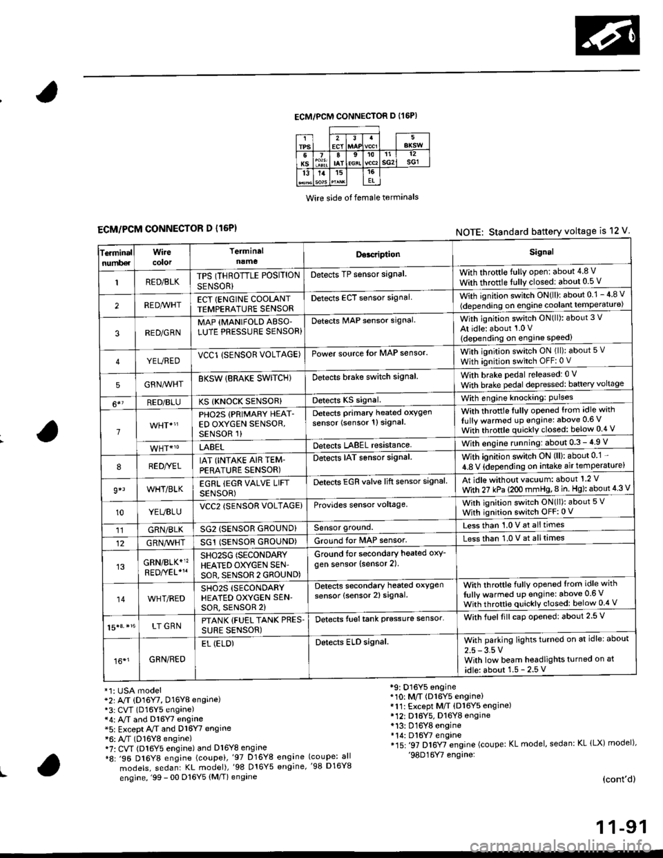
ECM/PCM CONNECTOR D I16P)
Wire side ot female terminals
ECM/PCM CONNECTOR D l16P)NOTE: Standard battery voltage is 12 V
Te.minalnumb€r
Wirecolor
Terminaln!meDor.riptionSignal
RED/BLKTPS (THROTTLE POSITION
SENSOR}
Detects TP sensor signal.With throttle fully open: about 4.8 V
With throttle fully closedl about 0.5 V
REDA/VHTECT {ENGINE COOLANTTEMPERATURE SENSORDetects ECT sensor signalWith ignition switch ON{ll): about 0.1 - 4 8 v
(depending on engine coolant lempe ratu re)
3RED/G RNMAP {MANIFOLD ABSO'LUTE PRESSURE SENSOR}Detects MAP sensor signal.With ignition switch ON(ll): about 3 V
At idle: about 1.0 V
{depending on engine speed)
YEUREDVCCl (SENSOR VOLTAGE)Power source lor MAP sensor.With ignition switch ON (ll): about 5 v
With ignition switch OFF: 0 V
5GRNMHTBKSW {BRAKE SWITCHIDetects brake switch signalWith brake pedal released: 0 v
With brake pedal depressed: baftery voltage
6*?RED/BLUKS {KNOCK SENSOR}Detects KS signal.With engine knocking: Pulses
1
PHO2S (PRIMARY HEAT-ED OXYGEN SENSOR,SENSOR 1)
Detects Primary heated oxygen
sensor (sensor 1l signal
With throttle fullv opened from idle with
Iully warmod up engine: above 0.6 V
With throttle quickly closed: below 0.4 v
LABELDetects LABEL resistanceWith engine r!nning:about 0.3 - 4.9 V
8RED//ELIAT (INTAKE AIR TEM-PERATURE SENSOR)
Detects IAT sensor signal.With ignition switch ON (ll): about 0 1 -
4.8 V {depending on intake air temperature)
9*lWHT/BLKEGRL iEGR VALVE LIFT
SENSOR)
Detects EGR valve lift sensor signalAt idle without vacuum: about'1 2 V
With 27 kPa (2OO mmHg,8 in. Hg): about 4 3 V
10YEUBLUVCC2 (SENSOR VOLTAGE)Provides sensor voltage,With ignition switch ON(ll): about 5 V
With ignition switch OFF:0 V
11GRN/BLKSG2 (SENSOR GROUND}Sensor ground.Less than 1.0 V at alltimes
12G RN,4/1r'HTSG1 (SENSOR GROUND)Ground for MAP sensor.Less than 1.0 V at alltimes
GRN/BLK*1?SHO25G (SECONDARY
HEATED OXYGEN SEN'
SOR, SENSOR 2 GROUND)
Ground for secondary heated oxy-
gen sensor (sensor 2).
14WHT/REDSH02S (SECONDARY
HEATED OXYGEN SEN'soR, sENsoR 2)
Detects secondary heated oxygen
sensor (sensor 2) signal.With throftle fully opened lrom idle with
fully warmed up engine: above 0.6 V
With throttle quickly closed: below 0.4 V
15|3. *15LT GRNPTANK {FUEL TANK PRES.
SURE SENSOR)
Detects fueltank prgssure sensor'With fuelfill caD opened: about 2.5 V
16*1GRN/RED
EL (ELD)Detects ELD signal.With parking lights turned on at idle: about
2.5 - 3.5 VWith low beam headlights turned on at
idle: about 1.5 - 2.5 V
*1: USA model*2r A/T (D16Y7, D16Y8 engine)*3: CVT (D16Y5 engane)*4: A,/T and Dl6Y7 engine*5: Except A/T and D16Y7 engine*6: A"/T (D16Y8 engine)i7: CVT (Dl6Y5 engine) and Dl6Y8 engine*8: .96 D16Y8 engine (coupei,'97 D16Y8 engine
models, sedanr KL model),'98 016Y5 engine,
engine, '99 - 00 D16Y5 (M/T) engine
*9: D16Y5 engine*10: M/T (D16Y5 engine)*11: Except M/T (Dl6Y5 engine)* 12r D16Y5. D16YB engine*13: D16Y8 engine*14: Dl6W engine*15: '97 D16Y7 engine (coupe: KL model, sedan: KL lLX) model),'98D16Y7 engine:(coupe: all'98 D16Y8
(cont'd)
1 1-91
Page 366 of 2189

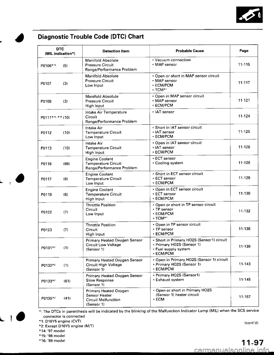
Diagnostic Trouble Code (DTCI Chart
connector is connecteda1: Dl6Y5 engine (CVT)*2: Except D16Y5 engine (M/T)*14:'97 model*15:'96 model*16: '98 model
(cont'd)
11-97
DTC
{MlL indication*lDelection liemProbable CausePage
Manifold Absolute
Pressure Circuit
Range/Performance Problem
. Vacuu m connection. MAP sensor11115
P0107 (3)
Manifold Absolute
Pressure Circuit
Low Input
Open or short in MAP sensor circuit
MAP sensor
ECMiPCM
TCM*1
11't1'l
P0108 (3)Manifold Absolute
Pressure Circuit
High Input
Open in MAP sensor circuit
MAP sensor
ECtvt/PCM
't 1 121
P0.111*14. *15 (10)
lntake Air Temperature
Circuit
Range/Performance Problem
. IAT sensor11-124
PO112 {10}
Intake Air
Temperature Circuit
Low Input
Short in IAT sensor circuit
IAT sensor
ECMiPCM
11-125
P0113 (10)lntake Air
Temperature Circuit
High Input
Open in IAT sensor circuit
IAT sensor
ECM/PCM
't1-126
P0116 (86)Engine Coolant
Temperature Circuit
Range/Performance Problem
. ECT sensor. Cooling system11-124
PO't't7 {6)
Engine Coolant
Temperature Circuit
Low Input
Short in ECT sensor circuit
ECT sensor
ECM/PCM
11-129
P0118 (6)Engine Coolant
Temperature Circuit
High lnput
Open in ECT sensor circuit
ECT sensor
ECM/PCM
11-130
?0122 t1l
Throttle Position
CircuitLow Input
Open or short in TP sensor circuit
TP sensorECM/PCM
TCM*1
11-132
P0123 (7)Throttle Position
Circuit
High Input
Open in TP sensor circuit
TP sensor
ECM/PClvl
11-136
P0131*' (1)
Primary Heated Oxygen Sensor
Circuit Low Voltage(Sensor 1)
Short in Primary HO2S (Sensorl ) circuit
Primary HO2S {Sensor 1)
Fuel supply system
ECM/PCM
1 1-139
P0132*' ('�r)
Primary Heated Oxygen Sensor
Circuit High Voltage(Sensor 1)
Open in Primary HO2S {Sensor 1} circuit
Primary HO2S (Sensor 1)
ECM/PCM
1 1- 143
P0133*' (61)
Primary Heated Oxygen Sensor
Slow Response(Sensor 1)
. Primary HO2S (Sensorl). Exhaust system11-145
P0135*? (41)
Primary Heated Oxygen
Sensor Heater
Circuit Malfunction(Sensor 1)
. Open or short in Primary HO2S(Sensor 1) heater circuit. ECM11-151
*: The DTCS in parenthesis will be indicated by the blinking of the Malfunction Indicator Lamp (MlL) when the SCS service
! ta
Page 368 of 2189

,'o
L
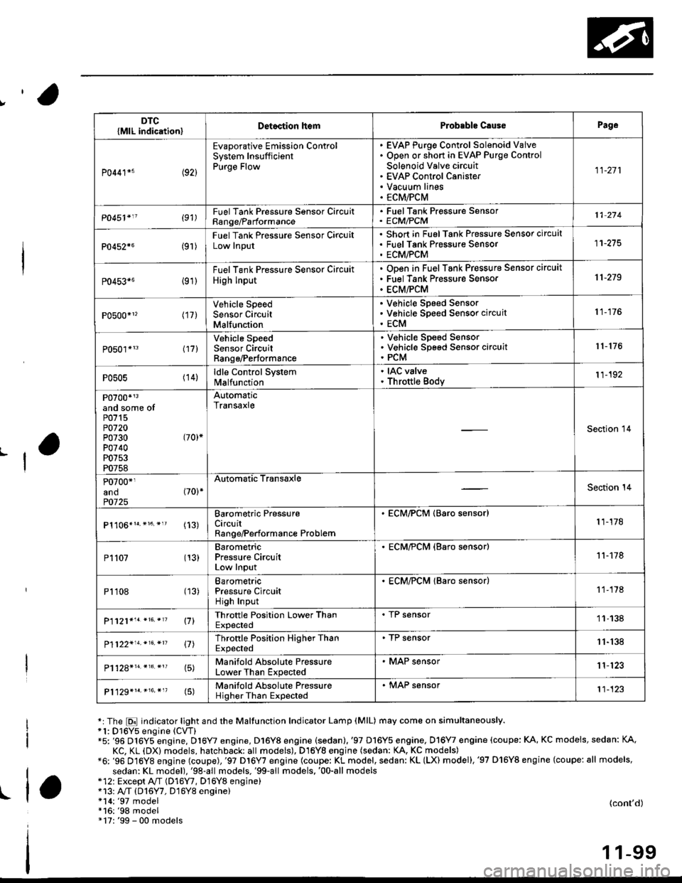
*:The E indicator light and the Maltunction Indicator Lamp (MlL) may come on simultaneously.*1: D16Y5 engine (CVT)"5: '96 D16Y5 engine, D16Y7 engine, D16Y8 engine (sedan).'97 D16Y5 engine, Dl6Y7 engine (coupe: KA, KC models, sedan: KA.
KC, KL (DX) models, hatchback: all models), D16Yg engjne (sedan: KA, KC models)*6: '96 D16Y8 engine (coupe),'97 Dl6Y7 engine (coupe: KL model, sedan: KL (LX) model),'97 D'16Y8 engine (coupe: all models,
sedan: KL model),'98-all models,'99-all models,'00-all models*12: Except A,,/T (D16Y7, D16Y8 enginei*13: A"/T (D16Y7, D16Y8 engine)!l*14:'97 model*16:'98 model" 17: '99 - 00 models
(cont'd)
1 1-99
DTC{MlL indication}Detoction lt€mProbable C.usePage
P0441*5 (92)
Evaporative Emission ControlSystem InsufficientPurge Flow
EVAP Purge Control Solenoid VaiveOpen or short in EVAP Purge Control
Solenoid Valve circuitEVAP Control CanisterVacuum linesECM/PCM
11-271
P0451'11 (91)FuelTank Pressure Sonsor CircuitRange/Parformance
. FuelTank Pressure Sensor' ECM/PCM11 274
P0452{6(9r )
Fuel Tank Pressure Sensor CircuitLow Input
Short in FuelTank Pressure Sensor circuatFuel Tank Pres$ure SensorECM/PCM
11-275
P0453*6 {91)
Fuel Tank Pressure Sensor Circuit
High Input
ODen in Fuel Tank Pressure Sensor circuit
Fuel Tank Pressure Sensor
ECM/PCM
11-219
P0500*1, (17)Vehicle SpeedSensor CircuitMalfunction
V€hicle Speed SensorVehicle Speed Sensor circuit
ECM
11-176
P0501*'3 l17l
Vehicle SpeedSensor CircuitRange/Performance
V€hicle Sp€ed SensorVehicle Speed Sensor circuitPCM
r 1- 176
P0505 (14)ldle Control Systemlvl a lfu n ctio n
. IAC valve. Throttle Body11-192
P0700*r3and some ofP0715P0720P0730 (70)*
P0740P0753P0758
AutomaticTransaxle
Section 14
P0700*1and (70)*
P0725
Automatic TransaxleSection 14
(13)Barometric PressureCircuitRange/Performance Problem
. ECM/PCM (Baro sensor)1 1-178
P1107 (13)BarometricPressure CircuitLow Input
. ECM/?CM (Baro s€nsor)11-178
P1108 (13)BarometricPressure CircuitHigh Input
. ECM/PCM lBaro sensor)1 1-178
P1121*'. *16. *'? \71Throttle Position Lower ThanExpected
. I r sensor11-138
P1122'14.*16.*n 17lThrottle Position Higher ThanExpected
. TP sensor11-'138
15)Manifold Absolute PressureLower Than Expected
. MAP sensor1 1'123
P1129*1r.*16.*"(5)Manifold Absolute PressureHigher Than Expected
. MAP sensor't1-123
Page 384 of 2189

Manifold Absolute Pressure (MAP) Sensor ('96 Models)
The scan tool indicates Diagnostic Trouble Code (DTC) P0106: A mechanical problem (vacuum leak) in the
Manifold Absolute Pressure (MAP) Sensor system'
TheMAPsensorconvertsmanifoIdabsoIutepressureintoeiectricaIsigna|sandinpUtstheEcM/PcM'
OUTPUTVOLTAGE
(v13.5
3.0
2.5
2.0
1.5
1.0
0.5
0lin. Hgl GAUGE
- The MIL has been reported on- OTC P0106 is storod.- Or from Ptobable Cause Lisl.
Problom verificetion:1. Do the ECM/PCM Reset Pro-
cedure.2. Start the engine and keep
engine speed at 1,000 rpm for
one minute with the transmis'
sion in @ or I Position {Mff
in neutral).
ls DTC P0106 indicated?
Check tor vacuum leakage or
blockage between the MAP sen'
sor and throftle bodyCheck the MAP sensor outPut:
1. Turn the ignition switch OFF
2. Turn the ignition switch ON (ll).
3. Check the MAP with the scan
tool.ls there leakage or blockage?
Chock the MAP s€nsol output:
1. Stop the engane.2. Turn the ignition switch ON (ll).
3. Check the MAP with the scan
tool.
READING300(mm Hgl
(To page 11 116)
{cont'd)ll,(To page 11-116)
1 1-1 15
Page 385 of 2189

PGM-FI System
(From page 11-115i{From page 11-115)
Chock to. poor response:1. Start the engine. Hold theengine at 3,000 rpm with M inE or E position, M/T in neutral untilthe radiator tan comeson, then turn the ignitionswitch OFF.2. Start the engine.3. Check the MAP with the scantool.
ls a N4AP ot 40.0 kPa {300 mmHg,12.0 in.Hg) or less indicated withinone second after staning theengine?
The MAP sensor is OK st this time.
Check lor poor response:1. Start the engine. Hold theengine at 3,000 rpm with M inE or E position, M/T in neu-tral until the radiator fan comeson, then turn the ignitionswitch OFF.2. Start the engine.3. Check the MAP with the scantool.
ls a MAP of 40.0 kPa (300 mmHg,12.0 in.Hg) or less indicated withinone second after starting theengine?
Substitute a known-good ECM/PCM and rechock. lt symptom/indication go6s .way. .6plrceth€ original ECM/PCM.
Manifold Absolute Pressure (MAP) Sensor ('96 Modelsl (cont'dl
11-116
Page 386 of 2189

Manifold Absolute Pressure {MAP} Sensor
('96 - 98 Models,'99 - 00 D16Y5 engine with M/T)
I
The scan tool indicates Diagnostic Trouble Code (DTC) PO107: A low voltage (high vacuum) problem in the
Manifold Absolute Pressure (MAP) sensor.
MAP SENSOR 3P CONNECTOR (C111)
vccr(YEL/BEDI
Wire side of female terminals
(D16Y5 engine (with
cw))T
YES
(cont'd)
11-117
Tho MIL has been roport€d on.
DTC P0107 is storod.
Problam verification:1. Turn the ignition switch ON (ll).
2. Check the MAP with the scan
lool.
lntormittont failuro, sYatgm ia OK
al thb timo. Chock lor Pool con_
noqtiona or looso wirca at C111
{MAP !6nsor) ond ECM/PCM.
ls approx. 101 kPa (760 mmHg,
30 in.Hg) indicated?
Chock for an opon in wiJe (VCCI
lino):1. Turn the ignition switch OFF.
2. Disconnect the MAP sensor
3. Turn the ignition switch ON (ll).
4. Measure voltage between the
MAP sensor connector No l
terminal and No 2 terminal
Ropair open in tho wit b€twocn
ECM/PCM (Dill tnd MAP !enso].ls there approx. 5 V?
Check for .n open or ahort in the
MAP 3€naor:Check the MAP with the scan
tool.
ls approx. 2 kPa (15 mmHg,
0.6 in.Hg) or less indicated?
Chsck to. a short in the TCM:
1. Turn the ignition switch OFF.
2. Disconnect the 22P connectorfrom the TCM.3. Turn the ignition switch ON
0r).4. check the MAP with the scan
tool.
(To page 11-118)
Page 387 of 2189

PGM-FI System
(From page 11-117)
ls approx. 2 kPa ('15 mmHg, 0.6in.Hg) or less indicated?
Check for a short in ihe wire{MAP line)l1. Turn the ignition switch OFF.2. Disco n nect the ECM/pCMconnector D (16P).
3. Check for continuity betweenthe MAP sensor connector No.3terminal and body ground.
R6pair lhort in tha wire b€twaenECM/PCM {D3l .nd MAP !6ru0r.
Substitute a known-good ECM/PCM..nd recheck. normal MAPis indiceted, .eplsce lhe originalECM/PCM,
Manifold Absolute Pressure (MAp) Sensor('96 - 98 Models,'99 - 00 D16Y5 engine with M/Tl (cont,d)
MAP SENSOR 3P CONNECTOR IC1l1I
MAP(RED/GRNI
Wire side of femate;rminats
11-118
Page 388 of 2189

|'Manifold Absolute Pressure (MAP) Sensor
(;gg - OO Models except Dl6Y5 engine with M/T)
The scan tool indicates Diagnostrc Trouble Code (DTC) PO1O7: A low input (high vacuuml problem in the
Manifold Absolute Pressure (MAP) sensor'
The MAp sensor converts manifold absolute pressure into electrical signals and inputs the ECM/PCM'
OUTPUTVOLTAGE
lvl3.5
3.0
2.5
2.0
1.5
1.0
0.5
0(in.Hgl GAUGEREAOING(mmHgllq, 2oo 3q, (x, 5q) 6q) 700
MAP SENSOR 3P CONNECTOR IC114)
vccltYEL/RED)
Wire sido of fomalg tormin6ls
.-l
- The MIL h'3 been reported on- OTC P0107 b stor€d.
Problem verilication:
1. Turn the ignition switch ON {ll)
2. check the N4AP with the scan
tool.
lntermittent failuro, 3Ystom is OK
at this time. Ch€ck for Poor con'
nection3 or loose wiros at C111
IMAP sonsorl and ECM/PCM.
ls approx. 101 kPa (760 mmHg,
30 in.Hg)indicated?
Ch.ck for an opcn in wit. {vCC1
linel:1. Turn the ignition switch OFF
2. Disconnect the MAP sensor
connector.3. Turn the ignition switch ON (ll).
4. Measure voltage between the
MAP sensor connector No. 1
terminal and No 2 terminal
Repair opsn in the wirg botween
ECM/PCM (C19) rnd MAP seGor.ls there approx. 5 V?
(To page 11-120)
{cont'd)
1 1-1 19