Page 1619 of 2189
A/T Gear Position Indicator
Component Location lndex
sRS components are located in this area. Review the sRS component locations, precautions, and procedures in the sRS
section (241 before performing repairs or service'
A/T GEAR POSITION INDICATOR
Input Test, page 23-152
A/T GEAR POSITION SWITCHTest, page 23 154Replacement, page 23-155
t
E
N
E
E
E
(A/TI
E
N
E
E
r
(cw)
23-149
Page 1623 of 2189

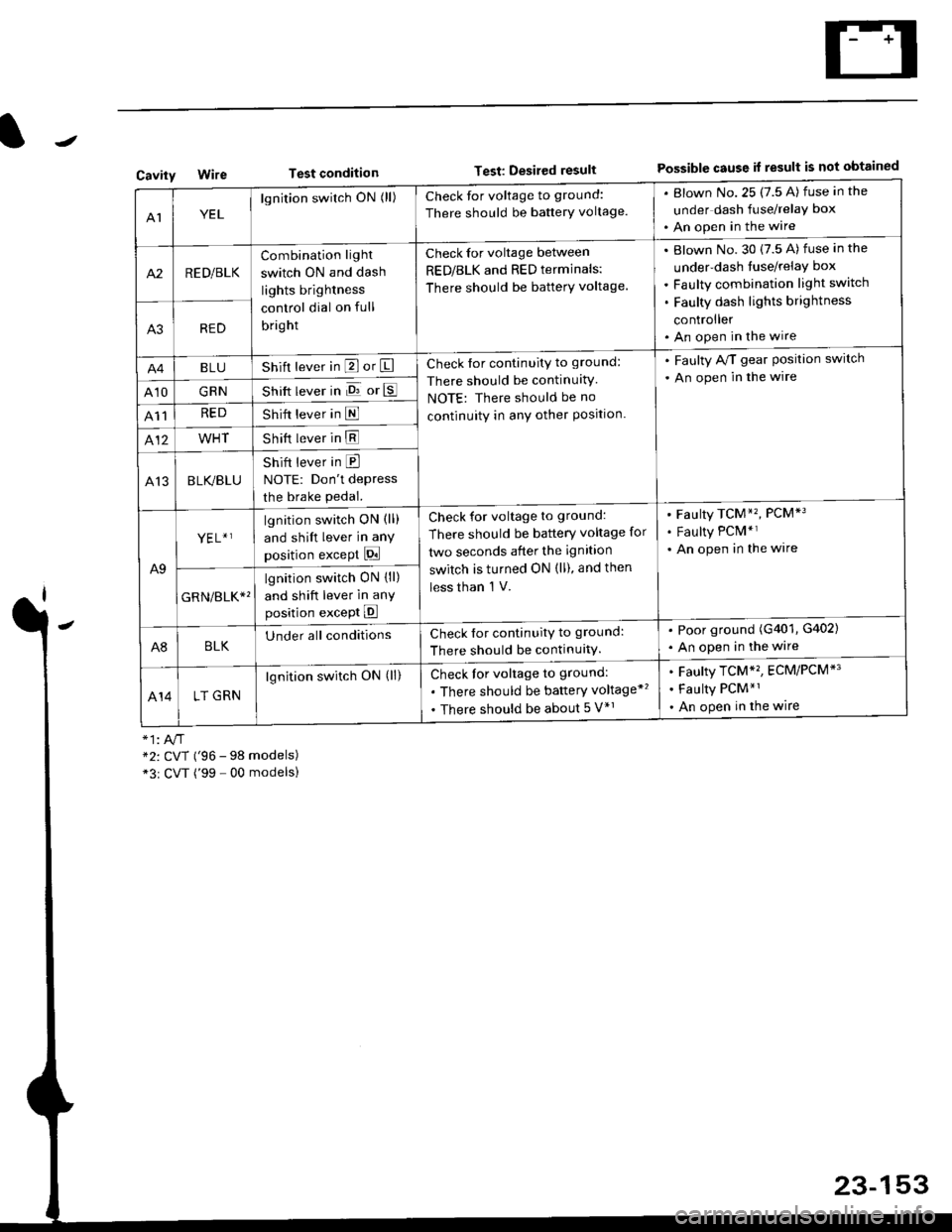
Test conditionTest: Desired resultPossible cause it result is not obtainedCavity
AIYEL
lgnition switch ON (ll)Check for voltage to ground:
There should be banerY voltage.
. Blown No.25 (7.5 A) fuse in the
under dash fuse/relay box
. An open in the wire
A2RED/BLK
Combination light
switch ON and dash
lights brightness
control dial on full
bright
Check for voltage between
RED/BLK and RED terminals:
There should be batterY voltage.
Blown No. 30 {7.5 A) fuse in the
under-dash tuse/relay box
Faulty combination light switch
Faulty dash lights brightness
controller
An open in the wireA3RED
BLUShift lever in P or ICheck for continuity to ground:
There should be continuitY
NOTE: There should be no
continuity in anY other Position.
. Faulty A/T gear Position switch
. An open in the wire
A10GRNShift lever in E or E
A11REDShift lever in E
412WHTShift lever in E
A13BLK/BLU
Shift lever in E
NOTE: Don't depress
the brake pedal.
A9
YEL+ ]lgnition switch ON (ll)
and shift lever in any
position except Pi
Check for voltage to ground:
There should be battery voltage for
two seconds after the ignition
switch is turned ON (ll), and then
less than 'l V.
Faulty TCM*'�, PCM*3
Faulty PCM*r
An open in the wire
GRN/err*'
lgnition switch ON {ll)
and shift lever in anY
position except E
A8BLKUnder all conditionsCheck for continuitv to ground:
There should be continuitY.
. Poor ground (G401, G402)
. An open in the wire
414LT GRN
lgnition switch ON (ll)Check for voltage to ground:
. There should be baftery voltage*'�
. There should be about 5 V*r
Faulty TCM*'�, ECM/PCM*'
Faulty PCM*1
An open in the wire
*2: CVT ('96 - 98 models)*3r CVT ('99 - 00 modelsl
23-153
Page 1624 of 2189
A/T Gear Position Indicator
A/T Gear Position Switch Test
1. Remove the front console (see section 2O).
2. Disconnect the 14P connector from the A/T gear position switch.
3. Check for continuity between the terminals in each switch position according to the table.
' Move the shift lever back and forth without pushing the shift lever at each switch position, and check for continuitywithin the range of free play of the shift lever.' lf there is no continuity within the range of free play, adjust the position of the switch as described on the nextpage.
Terminal side of male terminals
A/T Gear Position Switch
+ 1 : With cruise controlsystem
23-154
Eack - upLight SwitchNeutralPosition Switch
Page 1625 of 2189

A/T Gear Position Switch
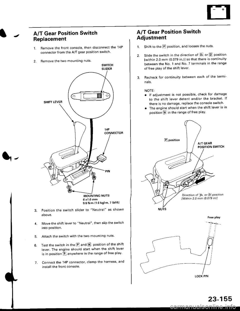
Replacement
1.
2.
7.
Remove the front console, then disconnect the
connector from the A/f gear position swltch
Remove the two mounting nuts
swrTcHSLIDEB
MOUNT'NG NUTS6x1 0mm98Nm(10kgtm'7lblftl
Position the switch slider to "Neutral" as shown
above.
Move the shift lever to "Neutral", then slip the switch
into position.
Aftach the swjtch with the two mounting nuts.
Test the switch in the E and E position ofthe shift
lever. The engine should start when the shift lever
is in position fl anywhere in the range of free play
Connect the 14P connector, clamp the harness, and
install the front console
14P
A/T Gear Position Switch
Adjustment
1.
3.
Shift to the E position, and loosen the nuts.
slide the switch in the direction of El or E position
lwithin 2.0 mm (0.079 in.)l so that there is continuity
between the No. 1 and No 7 terminals in the range
of free play of the shift lever'
Recheck for continuity between each of the termi-
nats.
NOTE:
. lf adjustment is not possible, check for damage
to the shift lever detent and/or the bracket lf
there is no damage. replace the console switch
. The engine should start when the shift lever is in
position N in the range of free play
E positionA/T GEARPOSITION SWITCH
Djrection of -on, or Dl Positionlwithin 2.0 mm (0.079 in)1
Free play
-lfr-
LOCK PIN
23-155
Page 1626 of 2189
Integrated Control Unit
UNDER,DASH FUS€/RELAY 8OX
IGNITION SWITCH
I wNDSHTELD II wrPEtuwAsHEF II swrTcH I
i Y **i,,*I wHT,tsLK II t_+
JV
Circuit Diagram
INTEGRATED CONTROL UNIT
8LK
G40tG402
WINOSHIELD WIPER/WASHER S-W|iCI.] ,
OFF/INT INT
f7 Y7
IIlltl
ttBLU/BLK YEUELU
ELUMHT
I
I
WINDSHIELDWIPEBMOTOH(As)
* 1 : Wilh mmbrned wiper washer operalion*2 : 96-98 models
UNDES H@O FUSE/RELAY BOX
6
,8-q
INTEEMITTENTWIPER RELAYCIRCUIT
"J COMBINEOWIPER.WASHENctncutT
WINOSHIELDWASHERMOTOR
23-156
Page 1627 of 2189
(A,4)
A,T GEARPosrfloN swlrcH _ _(Closed h posilon l?l ot [!l )
BLU/BLK -> [h'#f- |COMEINATIONLIGHT SWITCH
V
IREO/GRN
UNDEF.DASH FUSEi RELAY BOX
a
E
YEL
I
A iEi,I,B"'T
vll".i,l
| ,rr.nrorro .orrro, ,*,,
tt-
t(
rffi
|
BEMI\DEB crqcurl
lm
| /t I
tffinEoTsru REDTBLU BLIJ/RED clnculr
-neoieru | ,,-,r.0 J
l, "ulTo
/fP /Itr\
YVI onrveqs I or rtor
l3fifl&''' l5frl'.'
l (3'&T' 8iytr") l
(3&Y fiti'fJ"fl )
BLK BLK
TT
c552 G401
I
. BRAKE FLUIDLEVEL SWITCH. PARKING ERAKEswrTcH (usA)
' CEILING LIGHT. KEYLESS RECE VER CIRCUIT(ln lhe audio unil")
..aorr,rro Y
A
Iu$ut,""'
I3fif'�3#3trr,)-::
DRIVER'SDOOFswtTcHfolosed : Door open )(Open :Doordosed/
STARTERCUT FELAY
a
-
GFNi RED
23-157
Page 1629 of 2189

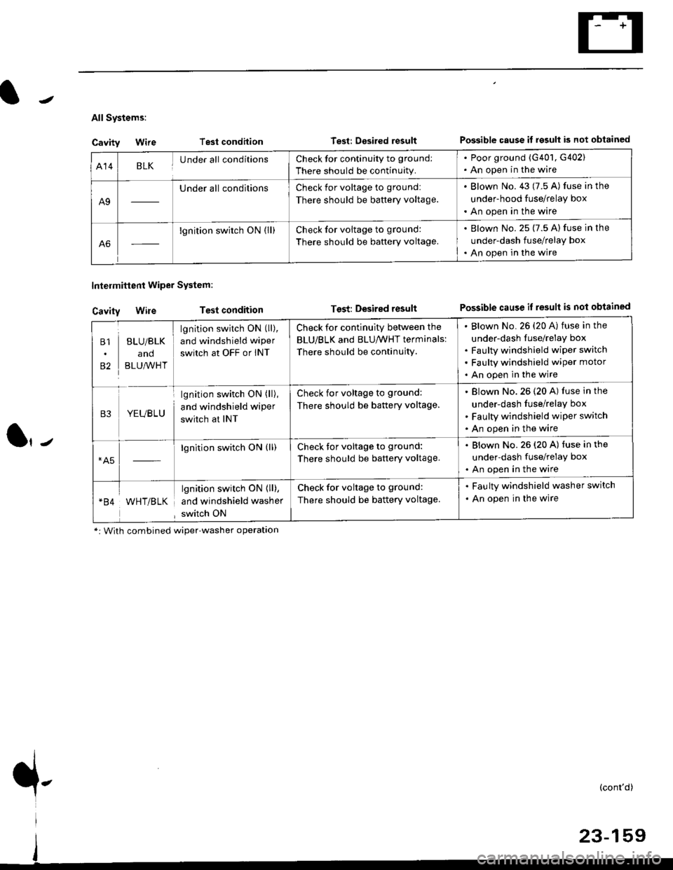
All Systems:
Cavity Wire
Cavity Wire
Intelmittent Wiper System:
Test condilion
Test condition
Test: Desired resultPossible cause il rgsull is not obtained
Test: Desired resultPossible cause if result is not obtained
Al4BLKUnder all conditionsCheck for continuity to ground:
There should be continuity.
. Poor ground (G401, G402). An open in the wire
A9
Under all conditionsCheck for voltage to ground:
There should be battery voltage.
. Blown No. 43 (7.5 A) fuse in the
under-hood fuse/relay box
. An open in the wire
A6
lgnition switch ON (ll)Check for voltage to ground:
There should be baftery voltage.
. Blown No. 25 (7.5 A) fuse in the
under-dash fuse/relay box. An open in the wire
B1
82
BLU/BLK
and
BLU,^/VHT
lgnition switch ON (ll),
and windshield wiper
switch at OFF or INT
Check for continuity between the
BLU/BLK and BLU/WHT terminals:
There should be continujty.
Blown No. 26 {20 A) fuse in the
under-dash fuse/relay box
Faulty windshield wiper switch
Faulty windshield wiper motor
An open in the wire
B3YEUBLU
lgnition switch ON (ll),
and windshield wiper
switch at INT
Check for voltage to ground:
There should be battery voltage.
Blown No.26 (20 A) fuse in the
under-dash fuse/relay box
Faulty windshield wiper switch
An open in the wire
*A5lgnition switch ON (ll)Check tor voltage to ground:
There should be battery voltage.
. Blown No.26 (20 A) fuse in the
under-dash fuse/relay box. An open in the wire
WHT/BLK
lgnition switch ON { ll),
and windshield washer
switch ON
Check for voltage to ground:
There should be battery voltage.
. Faulty windshield washer switch
. An open in the wire
*: With combined wiper'washer operatlon
{-(cont'd)
Page 1630 of 2189

Integrated Gontrol Unit
Input Test (cont'dl
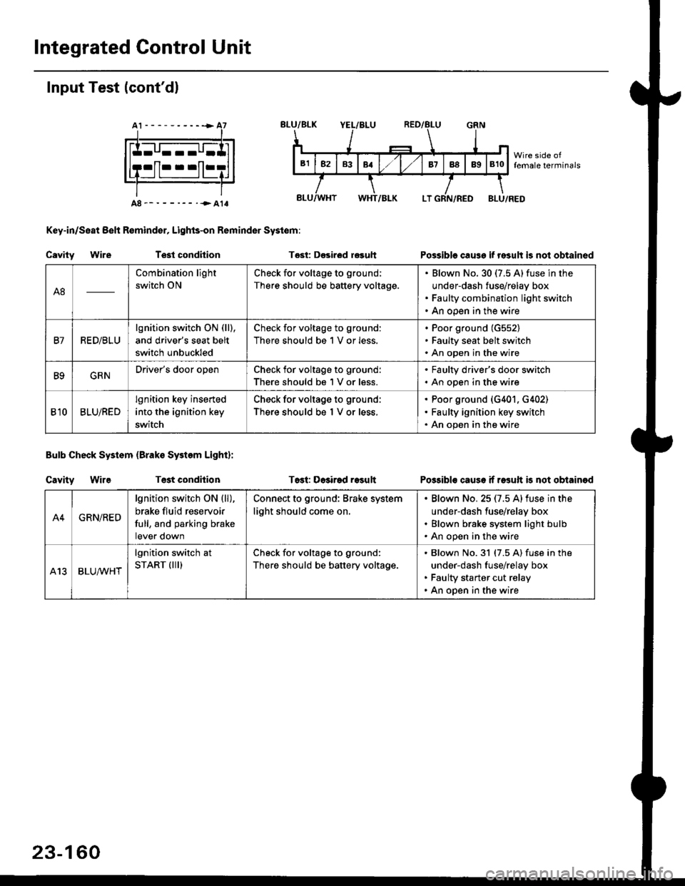
A8--------.--all
Key-in/Seat Belt R€mind€r, Lights-on Reminder Systom:
Cavity WireTest condhion
Bulb Check System (Brako System Light):
Cavity WireTest condilion
Tost: D€sirod r€guh
T6st: Dosirad result
Possible cause if result is not obtained
Possibls cause if rasuft b not obtainod
A8
Combination light
switch ON
Check for voltage to ground;
There should be battery voltage.
Blown No.30 (7.5 A)fuse in the
under-dash fuse/relay box
Faulty combination light switch
An open in the wire
B7RED/BLU
lgnition switch ON (ll),
and driver's seat belt
switch unbuckled
Check for voltage to ground:
There should be 1 V or less.
Poor ground (G552)
Faulty seat belt switch
An open in the wire
B9GRNDriver's door openCheck for voltage to ground:
There should be 1 V or less.
. Faulty driver's door switch. An open in the wire
Bl0BLU/RED
lgnition key inserted
into the ignition key
switch
Check for voltage to ground:
There should be 1 V or less.
Poor ground (G401. G402)
Faulty ignition key switch
An open in the wire
A4GRN/RED
lgnition switch ON {ll),
brake fluid reservoir
full, and parking brake
tever oown
Connect to ground: Brake system
light should come on.
Blown No.25 (7.5 Alfuse in the
under-dash fuse/relay box
Blown brake system light bulb
An open in the wire
A13BLUA/1r'HT
lgnition switch at
START (III)Check for voltage to ground:
There should be battery voltage.
Blown No.31 (7.5 A) fuse in the
under-dash fuse/relay box
Faulty starter cut relay
An open in the wire
23-160