2000 HONDA CIVIC service
[x] Cancel search: servicePage 189 of 2189
Cylinder HeadValve Guides
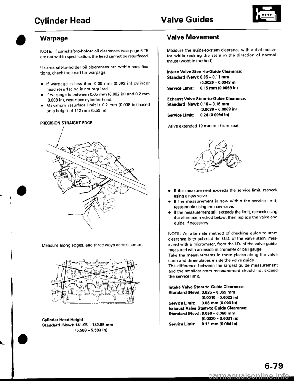
Warpage
NOTE: lf camshaft-to-holder oil clearances (see page 475)
are not within specification, the head cannot be resurfaced.
lf camshaft-to-holder oil clearances are within specifica-
tions, check the head for warPage.
. lf warpage is less than 0.05 mm (0.002 in) cylinder
head resurfacing is not required.
. lf warpage is between 0.05 mm (0.002 in) and 0 2 mm
(0.008 in), resurface cylinder head
. Maximum resurface limit is 0.2 mm (0.008 in) based
on a height of 142 mm (5.59 in).
PRECISION STRAIGHT EDGE
Measure along edges, and three ways across center'
Cylinder Head Height:
Standard lNewl: 1i11.95 - 142.05 mm
15.589 - 5.593 in)
Valve Movement
Measure the guide-to-stem clearance with a dial indica-
tor while rocking the stem in the direction of normal
thrust (wobble method).
lntake Valve Stem-to-Guide Cl6arance:
Standard (Newl: 0.05 - 0.11 mm
(0.0020 - 0.0043 inl
Service Limit: 0.15 mm {0.0059 inl
Exhaust Valve Stem-to-Guide Clealance:
Standard lNewl: 0.10 - 0.16 mm
(0.0039 - 0.0063 inl
Service Limit: 0.24 {0.0094 in)
Valve extended 10 mm out from seat.
lf the measurement exceeds the service limit, recheck
using a new valve.
lf the measurement is now within the service limit.
reassemble using the new valve
lf the measurement still exceeds the limit. recheck using
the alternate method below. then replace the valve and
guide, if necessary.
NOTE: An alternate method of checking guide to stem
clearance is to subtract the o.D. of the valve stem, mea-
sured with a micrometer, from the l.D. of the valve guide,
measured with an inside micrometer or ball gauge.
Take the measurements in three places along the valve
stem and three places inside the valve guide.
The difference between the largest guide measurement
and the smallest stem measurement should not exceed
the service limit.
lntake Valv€ Stem-to-Guide Clsarance:
Standard lNswl: 0.025 - 0.055 mm
10.0010 - 0.0022 inl
service Limit: 0.08 mm (0.003 in)
Exhaust Valve Stem-to Guide Cl€arance:
Standard {Newl: 0.050 - 0.080 mm
{0.0020 - 0.0031 inl
Service Limit 0.ll mm (0.004 in)
6-79
Page 205 of 2189
Connecting Rod and Crankshaft
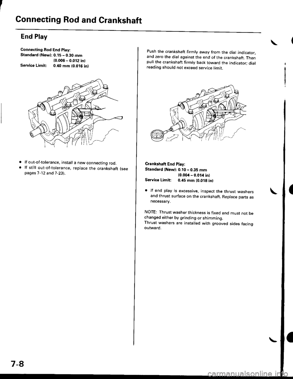
End Play
Connecling Bod End Play:
Standard (Newl: 0.15 - 0.30 mm
10.006 - 0.012 inlService Limit: 0.40 mm (0.016 inl
lf out-of-tolerance. install a new connecting rod.lf still out-of-tolerance, replace the crankshaft (seepages 7-12 and 7-23).
a
a
7-8
\
Push the crankshaft firmly away from the dial indicator,and zero the dial against the end of the crankshaft. Thenpull the crankshaft firmly back toward the indicator; dialreading should not exceed service limtr.
Grankshaft End Play:
Standard (Newl: 0.10 - 0.35 mm(0.00,f - 0.01,t inlServic€ Limit 0.it5 mm (0.018 in)
. lf end play is excessive, inspect the thrust washersand thrust surface on the crankshaft. Replace Darts asnecessary.
NOTE: Thrust washer thickness is fixed and must not bechanged either by grinding or shimmrng.Thrust washers are installed with grooved sides facingoutward.
Page 206 of 2189

Main Bearings
4.
Glearance
1.To check main bearing-to-journal oil clearance.
remove the main caps and bearing halves.
Clean each main journal and bearing half with a
clean shop towel.
Place one strip of plastigage across each main jour-
na l.
NOTE: lf the engine is still in the car when you bolt
the main cap down to check clearance, the weight
of the crankshaft and flvwheel will flaften the plasti-
gage further than just the torque on the cap bolt.
and give you an incorrect reading. For an accurate
reading, support the crank with a jack under the
counterweights and check only one bearing at a
time,
Reinstall the bearings and caps, then torque the
bolts.
lst step: 25 N'm (2.5 kgl'm. 18 lbf'ft)
FinalsteD:
B16A2 engine:
76 N.m (7.8 kgf.m, 56 lbf'ft)
D16Y5, Dl6Y7, D16Y8 engines:
51 N.m (5.2 kgf'm, 38 lbf'ft)
NOTE: Do not rotate the crankshaft during inspec-
tron.
Remove the cap and bearing again, and measure the
widest part ot the plastigage.
Main Boaring-toJournal Oil Clearance:
816A2 engine:
Standald {New}:
No. l, 2, 4, 5 Journals:
O.O2,l - 0.042 mm 10'00(B - 0.0017 in)
No. 3 Journals:
0.030 - 0.048 mm {0'0012 - 0'0019 in)
Servico Limit: 0.06 mm {0.002 in,
Dl6Y5, Dl6
r, Dl6Y8 engines:
Standard (Nsw):
No. 1,5 Journals:
0.018 - 0.035 mm {0.0007 - 0'001'[ in)
No. 2. 3, 4 Journals:
0.02,1 - 0.0,(2 mm {0'0009 - 0.0017 in}
Service Limit: 0.05 mm (0.002 in)
\
7-9
7.
lf the plastigage measures too wide or too narrow,
(remove the engine if it's still in the car), remove the
crankshaft, and remove the upper half of the bear-
ing. Install a new. complete bearing with the same
color code {select the color as shown on the next
page), and rechsck the clearance.
CAUTION: Do nol fil€, shim, or scrape the bearings
or tho cap3 to adiust cleatanc€.
lf the plastigage shows the clearance is still incor-
rect, try the next larger or smaller bearing (the color
listed above or below that one), and check again
NOTE: lf the proper clearance cannot be obtained
by using the appropriate larger or smaller bearings,
replace the crankshaft and start over.
Page 208 of 2189

Connecting Rod Bearings
Clearance
Remove the connecting rod cap and bearing half
Clean the crankshaft rod iournal and bearing half
with a clean shop towel.
Place plastigage across the rod journal.
Reinstall the bearing half and cap, and torque the nuts.
Torque
Bl6A2 engine:
40 N.m (4.1 kgl.m, 30 lbf'ft)
Dr6Y5, D16Y7, D16Y8 enginss:
31 N'm (3.2 kgf.m, 23 lbf ftl
NOTE| Do not rotate the crankshaft during inspection.
Remove the rod cap and bearing half and measure
the widest part of the plastigage.
Connecting Rod Bearing-to.Journal Oil Glearance:
816A2 engine:
Standard lNewl: 0.032 - 0.050 mm
10.0013 - 0.0020 in)
Service Limit: 0.06 mm 10.002 inl
D16Y5, D16Y7, D16Y8 engines:
Standard lNew): 0.020 - 0.038 mm
(0.0008 - 0.0015 in)
Service Limit 0.05 mm 10.002 inl
'1.
4.
lf the plastigage measures too wide or too narrow'
remove the upper half of the bearing, install a new,
complete bearing with the same color code (select
the color as shown in the right column), and
recheck the clearance.
CAUTION: Do not lile, shim, or scrape the bearings
or the caps to adiust clgarance.
lf the plastigage shows the clearance is still incorrect.
try the next larger or smaller bearing (the color listed
above or below that one), and check clearance again.
NOTE: lf the Droper clearance cannot be obtained
by using the appropriate larger or smaller bearings,
replace the crankshaft and start over.
PLASTIGAGE STRIP
\
7.
7-11
Selection
CAUTION: lf the codes are indecipherable because of
an accumulation of dirt and dust, do not sclub them
with a wile brush or scraper. Clean them only with sol-
vent or detergent,
Connecting Rod Code Location
Numbers have been stamped on the side of each con
necting rod as a code for the size of the big end Use
them, and the letters stamped on the crankshaft (codes
for rod journal size), to choose the correct bearlngs
Half of number ls
stamped on bearingcap and the otherhalf is stamped onrod.
Bearing ldentilication
Color code is on theedge ofthe bearing.
lfA--;T] |
lle"'tt l;llcorlll ll
I lD;;ilril |l-l
Larger brg end bore
Smaller Smallerrod bearlngjournal (thicker)
---------------- Smallerbearing{thrcker)
RedPinkGreen
PinkGreen
GreenErownBlack
GreenBrownBlackBlue
1234
Connecting Rod Journal Code Locations (Lettels)
Page 211 of 2189
Crankshaft
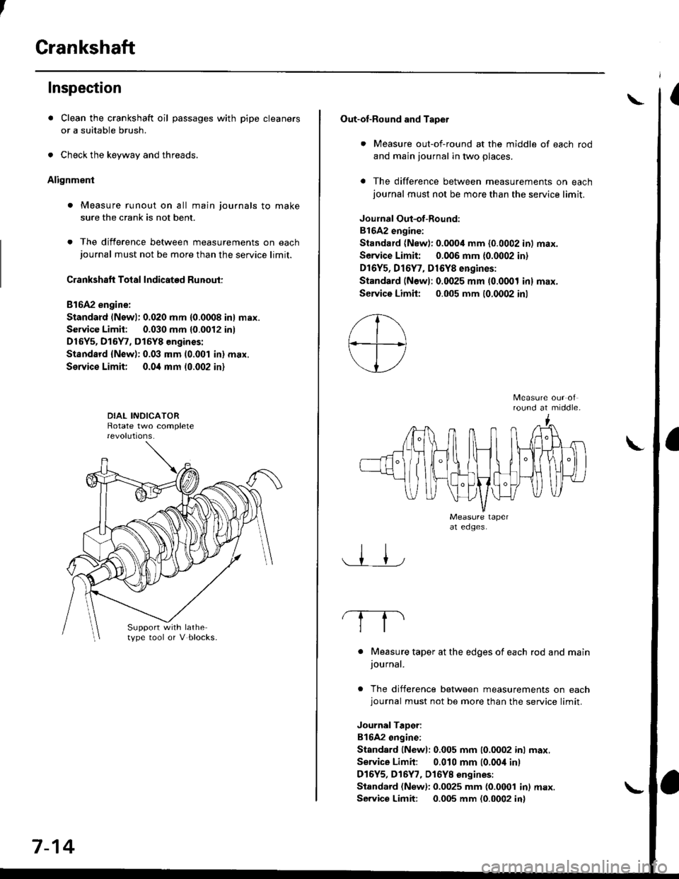
Inspection
. Clean the crankshaft oil passages with pipe cleaners
or a suitable brush.
. Check the keyway and threads.
Alignment
. Measure runout on all main journals to make
sure the crank is not bent.
. The difference between measurements on eachjournal must not be more than the service limit.
Crankshaft Total Indicated Runout:
Bl6A2 engine:
Standard (Newl: 0.020 mm {0.0008 in} max.
Service Limit: 0.030 mm {0.0012 inl
D16Y5, D15Y7, D15Y8 engines:
Standsrd {New): 0.03 mm (0.001 in} max.
Service Limit; 0.0i1 mm 10.002 in)
Support with lathetype tool or V blocks.
7-14
Out-of-Round and Tapet
. Measure out-of-round at the middle of each rod
and main journal in two places.
a The difference between measurements on eachjournal must not be more than the service limit.
Joulnal Out-of-Round:
81642 engine:
Standard (New): 0.0004 mm {0.0002 in) max.
Service Limit: 0.006 mm {0.0002 in)
Dr6Y5, Dl6Y7, D16Y8 engines:
Standard (Newl: 0.0025 mm (0.0001 inl max.
Service Limh: 0.005 mm (0.0002 inl
round at middle.
. Measure taper at the edges of each rod and mainjournal.
. The difference between measurements on eachjournal must not be more than the service limit.
JournalTaDer:
B16A2 ongine:
Standard lNewl: 0.005 mm (0.0002 inl max.
Service Limit: 0.010 mm (0.00i1 inl
D16Y5, D16Y7, Dl6YB engines:
Standard (New): 0.0025 mm {0.0001 in) max.
Service Limit: 0.005 mm (0.0002 in)
\
Page 212 of 2189
Pistons
Inspection
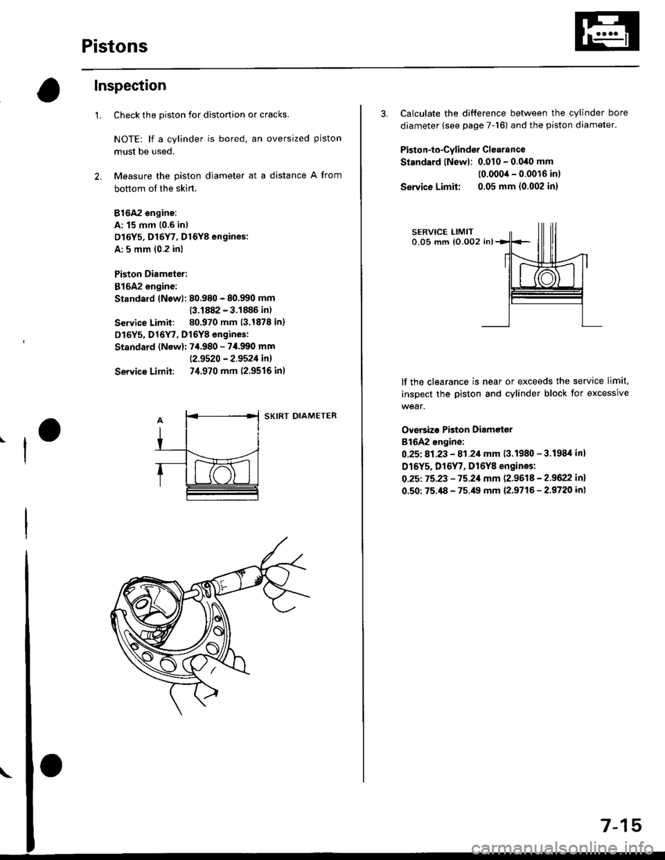
1.Check the piston for distortion or cracks,
NOTE: lf a cylinder is bored. an oversized piston
must be used.
Measure the piston diameter at a distance A from
bottom of the skirt.
816A2 engino:
A: 15 mm 10.6 in)
D16Y5, D16Y7, D16Y8 engines:
A: 5 mm (0.2 inl
Piston Diameter:
816A2 engine:
Standard lNewl: 80.980 - 80.990 mm
13.1882 - 3.1886 in)
Service Limit: 80.970 mm (3.1878 in)
D16Y5, D16Y7, D16Y8 engines:
Standard {New): 7,f.980 - 7i1.990 mm
|.2.9520 - 2.9521in!
Service Limit: 74.970 mm {2.9516 inl
SKIRT DIAMETER
57-1
3. Calculate the difference between the cylinder bore
diameter (see page 7-16) and the piston diameter.
Piston-to-Cylinder Clsarance
Standard lNewl: 0.010 - 0.0,10 mm
(0.0004 - 0.0016 inl
Servico Limit: 0.05 mm {0.002 in}
lf the clearance is near or exceeds the service limit,
inspect the piston and cylinder block for excessive
wear.
Oversizo Piston Diametor
816A2 ongine:
0.25t 81.23 - 81.21 mm (3.1980 - 3.1984 inl
D16Y5. D16Y7, D16Y8 engines:
O.25t 75.23 - 75.21 mm (2.9618 - 2.9622 in)
0.50: 75.i18 - 75.49 mm {2.9716 - 2.9720 in}
Page 213 of 2189
Cylinder Block
Inspection
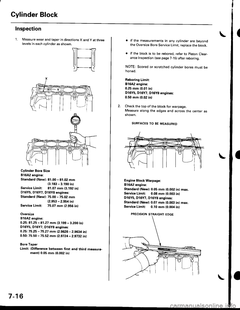
'LMeasure wear and taper in directions X and y at threelevels in each cvlinder as shown.
Cylinder Boro Size
816A2 engine:
Standard (Newl: 81.00 - 81.02 mm
{3.1t|:l - 3.190 intService Limit: 81.07 mm {3.192 in)D16Y5, D16Y7, D16Y8 engines:
Standard lNew): 75.00 - 75.02 mm(2.9s3 - 2.954 in)
Sarvice Limit: 75.07 mm (2.956 in)
Oversize
816A2 engiDe:
0.25t 41.25 - A1.27 mm {3.199 - 3.200 in)D16Y5, D16Y7, D16Y8 Engines:
0.25t 75.25 -15.27 mm (2.9626 - 2.963,0 in)0.50: 75.50 - 75.52 mm 12.9721- 2.9i32 inl
Bore TaDet
Limit: (Difference between first and third measure"ment) 0.05 mm (0.002 inl
7-16
lf the measurements in any cylinder are beyondthe Oversize Bore Service Limit, replace the block.
lf the block is to be rebored. refer to piston Clear-ance Inspection (see page 7-15) after reboring.
NOTE: Scored or scratched cylinder bores must behoned.
Reboring Limit:
Bl642 enginc:
0.25 mm (0.01 in)
Dl6Y5, D16Y7, D16Y8 engin€s:
0.50 mm (0.02 in)
Check the top of the block for warpage,Measure along the edges and across the center asshown.
SURFACES TO BE MEASUREO
Engine Block Warpage:
Bl6A2 engine:
Standard (Now): 0.05 mm {0.002 inl max.Service Limh: 0.08 mm (0.003 in)DtOYs, D16Y7, D16Y8 €nginas:
Standard (N€w): 0.07 mm l0.OO3 inl max.Servica Limit; 0.10 mm {0.00it in)
PRECISION STRAIGHT EDGE
Page 214 of 2189
Cylinder BlockPiston Pins
Bore Honing
1.Measure cylinder bores as shown on page 7-16. lf the
block is to be reused, hone the cylinders and remea-
sure the bores.
Hone cylinder bores with honing oil 8nd a fine (400
grit) stone in a 60 degree cross-hatch pattern.
NOTE:
. Use only a rigid hone with 400 grit or finer stone
such as Sunnen, Ammco, or equivalent.
. Do not use stones lhat are worn or broken.
When honing is complete, thoroughly clean the
engine block of all metal particles. Wash the cylin-
der bores with hot soapY water, then dry and oil
immediately to prevent rusting.
NOTE: Never use solvent. it will only redistribute the
grit on the cylinder walls.
lf scoring or scratches are still present in cylinder
bores after honing to the service limit, rebore the
cylinder block.
NOTE: Some light vertical scoring and scratching is
acceptable if it is not deep enough to catch your fin-
gernail and does not run the full length of the bore.
CYLINOES BLOCK
CYLINDER
NOTE:
. After honing, clean the cylinder thoroughly with
soapy warer.
. Onlv a scored or scratched cylinder bore must be
noneo.
Removal
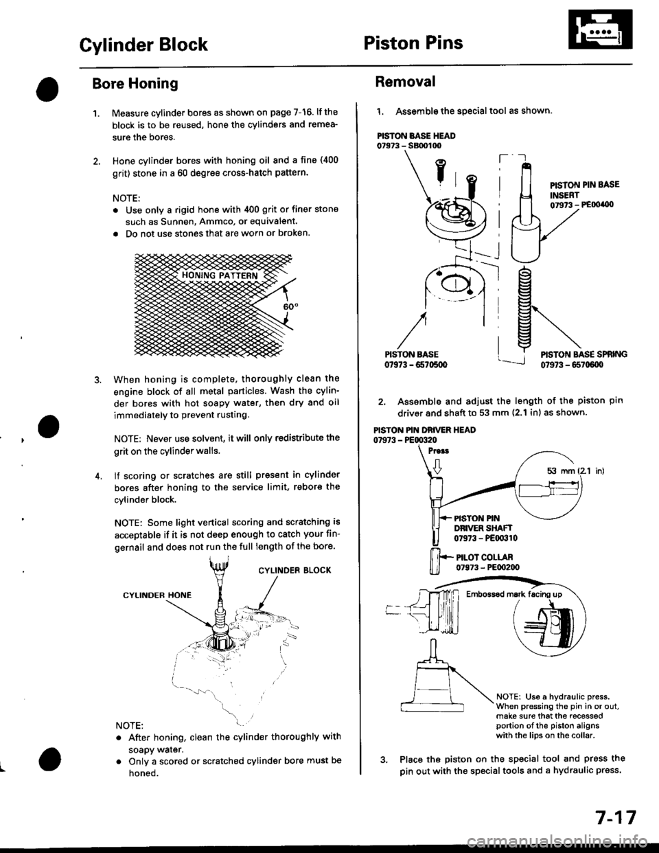
l. Assemble the special tool as shown.
PISTON BASE HEAD07973 - SBtx)too
ft
PISTON PIN BASE
INSERT01973 - PE00'0)
ptn
NOTEi Us6 a hydraulic press.When pressing the pin in or out.make sure that the recesssdportion of the piston alignswith the lips on the collar.
rg
g\
lj*N*,""
2. Assemble and adjust the length of the piston
driver and shaft to 53 mm (2.1 inl as shown.
PISTON PIN DRIVER HEAD07973 - PE00320
Proat
0
PISTON PINDRIVER SHAFT0t973 - PEqr310
PILOT COLLAR07973 - PE00200
3. Place the piston on the sp€cial tool and press the
pin out with the special tools and a hydraulic press.
Emboss6d mark facing up
7-17