2000 HONDA CIVIC ECU
[x] Cancel search: ECUPage 866 of 2189

Transmission
17.
Cooler Flushing (cont'dl
Make sure the transmission is in the E position.
Fill the transmission with ATF, and run the enginefor 30 seconds or until approximately 0.95 f (1.0 USqt.,0.8 lmp qt.) is discharged.
Remove the drain hose, and reconnect the coolerreturn hose to the transmission (see page l4-192).
Refill the transmission with ATF to the oroDer level(see page 14-118).
18.
19.
b
14-18A
TOOL MAINTENANCE
1. Empty and rinse after each use. Fill the can with waterand pressurize the can. Flush the discharge line toensure that the unit is clean.
2. lf discharge liquid does not foam, the orifice may beblocked.
3. To clean, disconnect the plumbing from the tank atthe large coupling nut.
ORIFICE
GRT{G
Remove the in-line filter from the discharge side andclean if necessary.
The fluid orifice is tocated behind the filter.Clean it with the pick stored in the bottom of thetank handle, or blow it clean with air. Securelvreassemble all Darts.
FILLER CAP
Page 868 of 2189

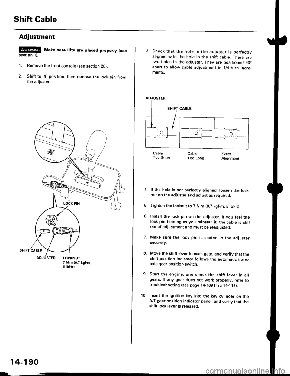
Shift Cable
Adjustment
@ Make sure lifts are ptaced properly (see
section 1).
1. Remove the front console (see section Z0l.
2. Shift to @ position. then remove the lock pin fromthe adiuster.
7 N.m (0.75 tbtftlkgtm.
14-190
3. Check that the hole in the adjuster is perfectlyaligned with the hole in the shift cable. There aretwo holes in the adjuster. They are positioned 90.apart to allow cable adjustment in 1/4 turn incre-ments.
ExactAlignment
4. lf the hole is not perfectly aligned, loosen the lock-nut on the adjuster and adjust as required.
5. Tighten the tocknut to 7 N.m (0.7 kgf.m, 5 tbf.ft).
6. Install the lock pin on the adjuster. lf you feel thelock pin binding as you reinstall it, the cable is stillout of adjustment and must be readjusted.
7. Make sure the lock pin is seated in the adjustersecuretv.
8. Move the shift lever to each gear, and verify that theshift position indicator follows the automatic trans-axle gear position switch.
9. Start the engine, and check the shift lever in allgears. lf any gear does not work properly, refer totroubleshooting (see page 14-109 thru 1'4-'112).
10. Insert the ignition key into the key cylinder on theAy'T gear position indicator panel, and verify that theshift lock lever is released.
CableToo ShortCableToo Long
Page 870 of 2189

Shift Indicator PanelATF Cooler Hoses
Adiustment
'1.Check that the index mark on the indicator alionswith the N mark on the shift indicator panel whenthe transmission is in NEUTRAL.
3 N.m {0.3 kgf.m, 2lbt.ftl
lf not aligned. remove the front console {see section20t.
Remove the shift indicator panel mounting screwsand adjust by moving the panel,
NOTE: Whenever the shift indicator panel is removed,reinstallthe panel as described above,
INDEX MARK
L
14-192
Connection
1. Connect the ATF cooler hoses to the ATF cooler linesand ATF cooler, and secure them with the clips asshown.
TRANSMISSION CLIP
Page 920 of 2189

Troubleshooting Flowchart - Vehicle Speed Sensor (VSS)
NOTE: Record all freeze data before you troubleshoot'
Po$rible Ctuse
. Disconnected vehicle speed
sensor (VSS) connectol. Short or open in VSS wire' Faulty VSS
@. Make sure lifts, iacks, and sal€tY stands are placed properly lsoe section 1)'
. Set the parking brake securelv, and block the rear wheels'
. iacr upile rront or the vehicle, and support it with safety st'nds'
TCM CONNECTORS
Wire side of female terminals
. OBD ll Scan Tool indicates Code
P1791.. Setf-diagno3is E indicato. light
blinks tour times.
Refer to seclion 23 for vehicle
soeed sensor IVSSI test
Check the VSS Voltage:
1. Raise the vehicle2. Shift the transmission to lEposrtlon.3. Disconnect the A (26P) and B(22P) connectors from the
TCM.4. Turn the ignition switch ON {ll).
5. Rotate the front wheel and
check for the voltage between
the 85 and 413 or A26 termi-
nals. Block the other wheel so
at does not turn
Check for oP€n in the wire
between the 85 terminal and the
vehicle speed sensor {VSS}. lf
wire is OK, check the vSS (see
soction 23).
Does0Vandapprox 5 V or more
appear alternatelY?
Check for loos€ TCM connedors
lI nec€ssary, substitute a known'
good TCM and recheck.
14-243
Page 970 of 2189

Start Clutch Control@
T
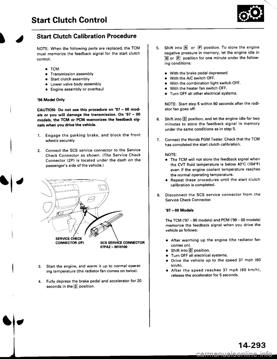
Start Clutch Calibration Procedure
NOTE: When the following parts are replaced, the TCM
must memorize the feedback signal for the start clutch
control.
. TCM
. Transmissionassembly
. Stan clutch assembly
. Lower valve bodv assembly
. Engine assembly or overhaul
'96 Model Only
CAUTION: Do not uso this procsdure on'97 - (X) mod-
els or you will damage the transmission. On '97 - 00
models, the TCM or PCM memorizes ths loodback sig'
nals when you drive the vehicle.
1. Engage the parking brake, and block the front
wheels securely.
2. Connect the SCS service connector to the Service
Check Connector as shown. (The Service Check
connector (2P) is located under the dash on the
passenger's side of the vehicle.)
CONNECTOR07PAZ - lDl01(xt
Start the engine, and warm it up to normal operat-
ing temperature (the radiator fan comes on twice).
Fully depress the brake pedal and accelerator for 20
seconds in the E] position.
rl ,
CONNECTOR I2PI
14-293
7.
Shift into E o|. E position. To store the engine
negative pressure in memory. Iet the engine idle in
E or E position for one minute under the follow-
ing conditions:
. With the brake pedal depressed,
. with the y'\/c switch oFF.
. With the combination light switch OFF.
. With the heater fan switch OFF.
. Turn OFF all other electrical systems
NOTE: Start step 5 within 60 seconds after the radi-
ator fan goes off.
Shift into E position, and let the engine idle for two
minutes to store the feedback signal in memory
under the same conditions as in step 5.
Connect the Honda PGM Tester. Check that the TCM
has completed the start clutch calibration.
NOTE:
. The TCM will not store the feedback signal when
the CVT fluid temperature is below 40"C (104'F)
even if the engine coolant temperature reaches
the normal operating temperature.
. Repeat these procedures until the start clutch
calibration is completed-
Disconnect the SCS service connector from the
Service Check Connector.
'97 - 00 Models
The TCM ('97 - 98 models) and PCM ('99 - 00 models)
memorize the feedback signal when you drive the
vehicle as follows:
. After warming up the engine (the radiator fan
comes onl.
. Shift into E position.
. Turn OFF all electrical systems,
. Drive the vehicle up to the speed 37 mph (60
km/h).
. After the speed reaches 37 mph (60 km/h),
release the accelerator for 5 seconds.
Page 977 of 2189

Pressure Testing
. While testing, be careful of the rot8ling front wheels.
. M8k6 suro lifts, iacks, and satety stands are placed properly lsee section 11.
CAUTION:
. Before testing, be sur. the transmb3ion fluid is fillod to the propor lcvel.. Warm up the engin€ to nolmal operating tsmperature bofore testing. While t€sting, be 3ure not to allow dust and other loreign particles to onler into the transmi$ion.
1. Raise the front of the vehicle, and support it with safety stands (see section 1).
2. Set the parking brake. and block both rear wheels securely.
3. Allow the front wheels to rotate freely.
4. Warm up the engine (the radiator fan comes on), then stop arid connect a tachometer.
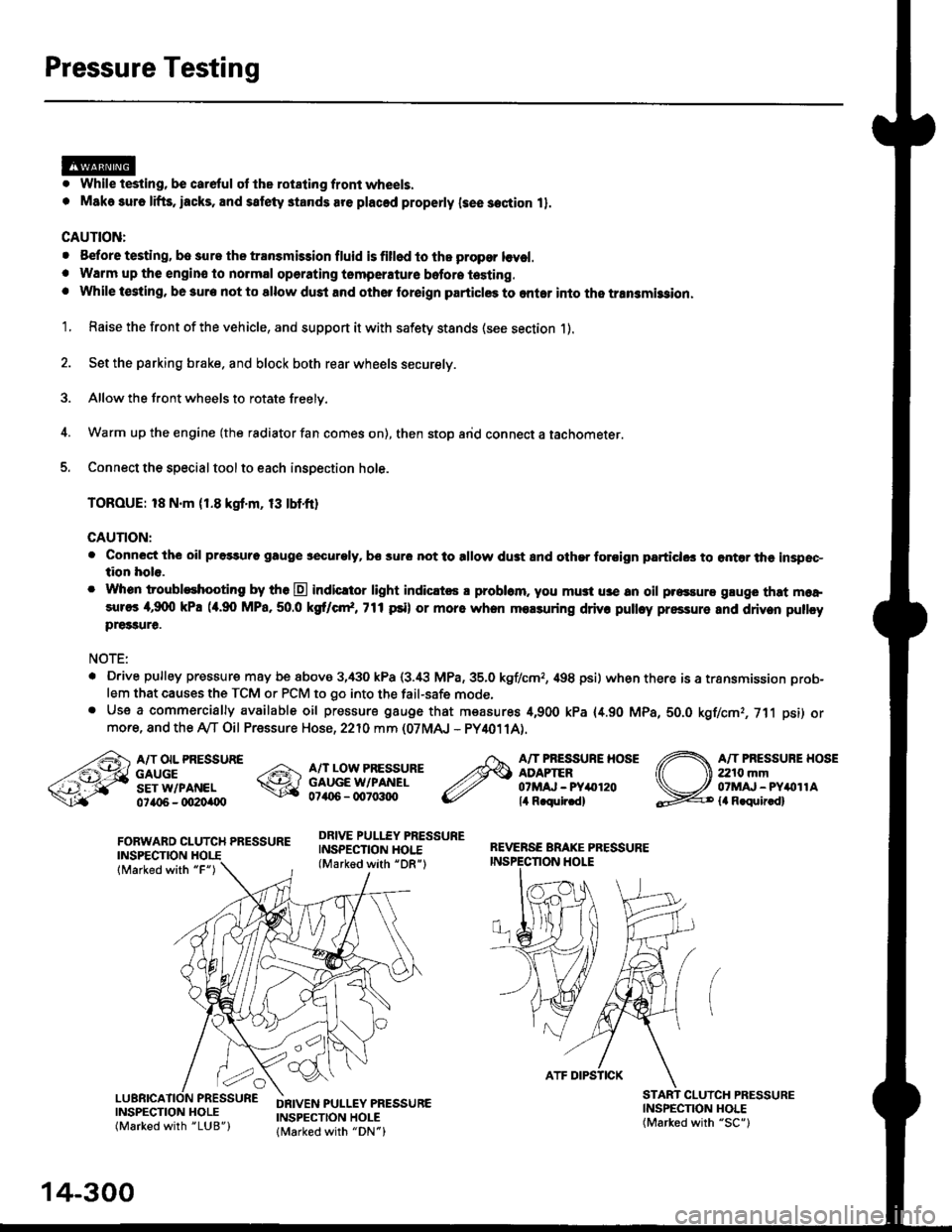
5. Connect the special tool to each inspection hole.
TOROUE: 18 N.m (1.8 kgt'm, 13 tbtfr)
GAUTION:
. Connect the oil pressuro gauge !!€curoly, bs sur6 not to allow dust and other foroign particlG3 to ontar the inspsc-tion hole.
. Whon troubleshooting by tho E indicltor light indic.t6 a problam. you mu3t u3e an oil p.essure gluge that moa,sures 4,9(X) kPa (a.90 MPa,50.0 kS cr*,771psi) or more when molsuring driv. pulley pressure and driven pullcypre33ure.
NOTE:
. D.ive pulley pressure may be above 3,430 kPa (3.i8 MPa,35.0 kgf/cmr, 498 psi) wh€n there is a transmission prob-
lem that causes the TCM or PCM to go into the fail-safe mode,. Use a commercially available oil pressure gauge that measures 4,900 kPa {4.90 MPa, 5O.O kgf/cmr, 711 psi) ormore, and the Ay'T Oil Pressure Hose, 2210 mm (07MAJ - PY4011A).
FORWARD CLUTCH PRESSUREINSPECTION
lMarked with "F")
REVERSE BRAKE PRESSUREINSPECTION I.IOLE
A/T OIL PRESSUREGAUGESET W/PANEL0ta{r6 - oO2Oi|(Xt
A/T LOW PRESSUREGAUGE W/PANEL0706 - qt7o:t{ro
DRIVE PULLEY PRESSUREINSPECTION HOI.E(Marked with "DR")
A/T PRESSURE HOSEADAPTER07MAJ - PYar'120lil R.qulr.d)
A/T PRESSUBE HOSE2210 mm07MAJ - PYitollAla R.quir.d)
(
INSPECNON HOLE(Marked with "SC")
CLUICH PRESSURE
INSPECTION HOLE(Marked with "LUB")
DRIVEN PULLEY PRESSUREINSPECTION HOLElMarked with "DN")
14-300
ATF DIPSTICK
Page 979 of 2189

Lower Valve Body Assembly
Replacement
@ Make sure lifts, iacks, and saf€ty stands
are placsd prop€rly {sea section 1).
CAUTION: While removing and installing th6 lower
valve body asssmbly, b€ sule not to allow dust and
other for€ign particles to entsr inio the transmksion.
1. Raise the front of the vehicle, and support it with
safetv stands (see section 1).
2. Set the parking brake, and block both rear wheels
securetv.
4.
6.
Remove the drain plug, and drain the CVT fluid.
Reinstall the drain plug with a new sealing washer(see page 1+299).
CAUTION: Keop all of other toreign parliclos out of
the transmission.
Disconnect the 8P connector from the solenoid har-
ness connector.
Remove the ATF cooler hoses at the ATF cooler
lines. Turn the ends of the ATF cooler hoses up to
prevent ATF from flowing out, then plug the ATF
cooler noses.
CAUTION: Keep all of other foroign particlo3 out of
tho transmission.
Remove the right front mounvbracket.
10 x 1.25 mmila N.m (,1.5 kgf.m, 33 lbtft)
RIGHT FRONTMOUNT/BRACKET
ATF COOLER LINE
10 x 1.25 mmsil N.m 15.5 kgf.m,40 rbr.ft)
ATF COOLER HOSE
14-302
14.
7. Remove the ATF cooler outlet line.
8. Remove the ATF cooler line bracket bolt.
9. Remove the ATF pan (fourteen bolts).
10. Remove the ATF strainer (two bolts).
1 l. Remove the one bolt securing the solenoid harness
connector,
12. Remove the
bolts).
lower valve body assembly (eight
LINE BOLT28 N.m (2.9 kgtm,21 lbtft)SEALINGReplace.
ATF COOI.-EROUTLET
OOWEL PIN
O.RINGFeplace.
SOLENOIO HARNESSCONNECTOR
5x1.0mm12 N.m 11.2 kgt.m,8.7 tbt.ftlO.RINGReplace.ATFSTNAINER
6x1.0mm12 N.m 11.2 kgt m,E.7 tbt'ft)
OOWEL NN
BODY ASSEMBLY
6x1.0mm12 N.m 11.2 kgf.m,8.7 rbf.ft)
ATF PAN GASKETReplace.
VALVE
ATF COOLER INLETUNE BRACKET BOLT8 x 1,25 mm26 N.m {2.7 kgf.m,20 tbf.frl
13.
ATF PANx 1.0 mm12 N.m 11.2 kgf.m, E.7 lbf.ftl
Install the new lower valve bodv in the reverse
ordgr of the removal orocedure.
CAUTION: Koep all ot other fo.oign particles out of
ths transmission.
NOTE:
. Replace the following parts:
- O-rings on the solenoid harness connector
and the ATF strainer- ATF pan gasket- Sealing washers
. lf the ATF cooler inlet line bracket is bent or
warped, put it back to the original position.
Perform the start clutch calibration orocedure on
page 14-293.
Page 980 of 2189

ATF Filter
l.Removal/lnstallation
!@ Make sure lifts, lEcks, snd safoty stands
ara pl8ced properly {sae section 1).
CAUTION: While removing and installing the ATF tilier,
be sure not to allow dust or other for6ign particle3 to
enter thg transmission.
1. Raise the front of the vehicle, and support it with
safety stands (see section 1).
2. Set the parking brake, and block both rear wheels
securely.
3. Remove the drain plug, and drain the CVT fluid.
Reinstall the drain plug with a new sealing washer
{see page 14-299).
fl,
5.
CAUTION: Keep all toreign particles out ot the
transmission.
Remove the ATF cooler hoses at the ATF cooler
lines. Turn the ends of the ATF cooler hoses up to
prevent ATF from flowing out, then plug the ATF
cooler noses.
CAUTION: Keep all foreign particles out of the
transmission.
Remove the right front mounvbracket.
10 x 1.25 mm4{ N.m {i1.5 kgf.m,33 lbf ft)
ATF COOLER LINE
10 x 1.25 mm54 N.m {5.5 kgt'm,
40 rbl.ft)
ATF COOLER HOSE(|'t
14-303
6. Remove the ATF cooler outlet line.
7. Remove the ATF cooler line bracket bolt.
8. Remove the ATF pan (fourteen bolts)
9. Remove the ATF cooler inlet line from the ATF pan
(three bolts).
10. Remove the ATF filter, and clean it.
11. Check that the ATF filter is in good condition.
12. Replace the ATF filter if it is clogged.
LINE BOLT28 N.m {2.9 kgf.m,21 lbt.ft)
ATF COO1TR OUTIET
6x1.0mm
ATF COOLER INI-ETLINE ERACKET BOLT8 x 1.25 mm26 N.m (2.7 kgt.m,20 rbtftt
O.RINGReplace.
ATF
ATF FILTER
ATF PAN
6x1.0mm12 N.m (1.2 kgt'm,8.7 lbl'ft)
lnstall the ATF filter in the reverse order of the
removal procedure.
GAUTION: Keep all foreign particles out ot the
transmission,
NOTE:
Replace the O-rings, the ATF pan gasket and
sealing washers.
lf the ATF cooler inlet line bracket is bent or
warped. put it back to the original position
GASKETReplace.
'13.
12 N m (1.2 kgf m,