2000 HONDA CIVIC Switch ignition
[x] Cancel search: Switch ignitionPage 2070 of 2189
Security System (cont'd)
Starter Cut Does Not Work Properly
(cx, Dx)
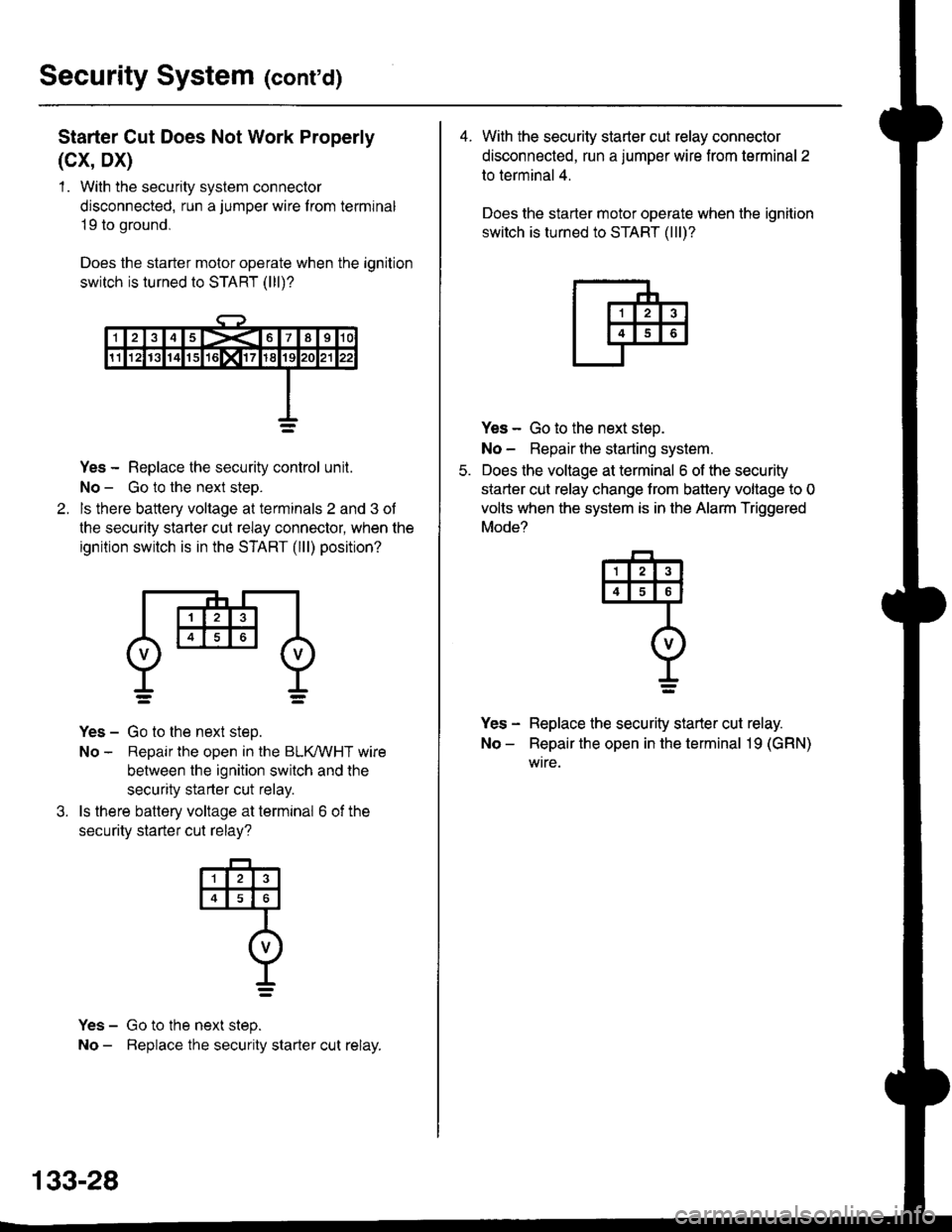
1 . With the security system connector
disconnected, run a jumper wire f rom terminal
19 to ground,
Does the starter motor operate when the ignition
switch is turned to START (lll)?
Yes - Replace the security control unit.
No - Go to the next steo.
ls there battery voltage at terminals 2 and 3 of
the security starter cut relay connector, when the
ignition switch is in the START (lll) position?
Yes - Go to the next step.
No - Repair the open in the BLKMHT wire
between the ignition switch and the
security starter cut relay.
ls there battery voltage at terminal 6 of the
securitv starter cut relav?
Yes - Go to the next step.
No - Beplace the security starter cut relay.
4
o
t_=
133-28
4. With the security starter cut relay connector
disconnected, run a jumper wire from terminal 2
to terminal 4.
Does the starter motor operate when the ignition
switch is turned to START (lll)?
Yes - Go to the next steo.
No - Repair lhe starting system.
Does the voltage at terminal 6 of the security
starter cut relay change trom battery voltage to 0
volts when the system is in the Alarm Triggered
Mode?
Yes - Replace the security starter cut relay.
No - Repair the open in the terminal 19 (GRN)
wtre.
q
I=
Page 2075 of 2189
How the Circuit Works
The two outside mirrors are controlled by the power
mirror switch. Each mirror has two reversible
motors: one motor moves the mirror up and down
and the other motor moves the mirror lett and right.
The power mirror switch contains four switches to
control mirror adjustment, and two switches to
select the left or right mirror With the ignition in ON
(ll), battery voltage is supplied to the power mirror
swrtch. The mirror selector switch directs voltage
from two of the direction switches to either the left
or the right mirror.
Mirror Up
When you press the "up" edge of the mirror
adjustment button, ground is supplied from one of
the up/down switch contacts to both mirrors; battery
voltage is supplied from the opposite up/down
switch contact through the mirror select switch. lf
the mirror select switch is in the left or right position,
battery voltage is supplied to the corresponding
mirror uo/down motor which then tilts the selected
mtrror uD.
Mirror Down
When you press the "down" edge of the mirror
adjustment button, battery voltage is supplied Irom
one of the up/down swilch contacts to both mirrors;
a ground is supplied from the opposite up/down
switch contact through the mirror select switch. lf
the mirror select switch is in the left or right position,
battery voltage is supplied to the corresponding
mirror up/down motor which then tilts the selected
mrrror oown.
Mirror Left
When you press the "|eft" edge of the mirror
adjustment button, battery voltage is supplied from
one of the lefuright switch contacts to both mirrors;
a ground is supplied from the opposite lefuright
switch contact through the mirror select switch. lf
the mirror select switch is in the left or right position,
battery voltage is supplied to the corresponding
mirror lefvright motor which then tilts the selected
mirror to the lett.
Mirror Right
When you press the "right" edge of the mirror
adjustment button, ground is supplied from one of
the lefvright switch contacts to both mirrors; battery
voltage is supplied from the opposite left/right switch
contact through the mirror select switch. lf the mirror
select switch is in the left or right position, battery
voltage is supplied to the corresponding mirror
lefuright motor which then tilts the selected mirror to
the right.
Refer to the Service Manual (Section 23, Electrical)
for speclfic tests of troubleshooting procedures
141-1
Page 2077 of 2189
How the Circuit Works
The two outside mirrors are controlled by the power
mirror switch. Each mirror has two reversible
motors: one motor moves lhe mirror uo and down
and the other motor moves the mirror left and right.
The power mirror switch contains four switches to
control mirror adjustment, and a switch lo select
the left or right mirror. With the ignition ON (ll),
battery voltage is supplied to the power mirror
switch. The mirror selector switch directs voltage
Irom the direction switches to either the left or rioht
mtrror.
Mirror Up
When you press the "up" edge of the mirror
adjustment button, voltage is supplied from one of
the UP switch contacts to both mirrors. With the
mirror select switch in the LEFT or RIGHT Dosition.
ground is provjded for the corresponding up/down
motor through the opposite UP switch contact.
Battery voltage is supplied to the mirror up/down
motor which then tilts the selected mirror uo.
Mirror Down
When you press the "down" edge of the mirror
adjustment button, ground is provided through one
of the DOWN switch contacts to both mirrors.
With the mirror select switch in the LEFT or RIGHT
position, voltage is supplied to the corresponding
up/down motor through the opposite DOWN switch
contact. Battery voltage is supplied to the mirror
up/down motor which then tilts the selected
mtrror down.
Mirror Left
When the mirror select switch is in the LEFT or
RIGHT position, and you press the "lett" edge of the
mirror adjustment button, voltage is supplied to both
corresponding mirror motors through one of the
LEFT switch contacts. Ground is provided for the
corresponding lefvright motor through the opposite
LEFT switch contact, 8attery voltage is supplied to
the mirror left /right motor which then tilts the
selected mirror left.
I,J
141-3
Mirror Right
When the mirror select switch is in the LEFT or
RIGHT position, and you press the '?ight" edge of
the mirror adjustment button, ground is provided to
both corresponding mirror motors through one of
the RIGHT switch contacts. Voltage is supplied to
the corresponding leruright motor through the
opposite RIGHT switch contact. Battery voltage is
supplied to the mirror left /right motor which then
tilts the selected mirror right.
Mirror Detoggers
With the ignition switch in ON (ll), battery voltage is
supplied to the mirror defogger switch. When you
press the mirror defogger switch ON, voltage is
supplied to both mirror defoggers, causing them to
heat up and remove any fog from the mirrors. The
opposite side of each defogger grid is connected to
g rou no.
Refer to the Service Manual (Section 23,
Body Electrical) for specific tests and
troubleshooting procedures.
Page 2124 of 2189
-57. c723
- Connects heater-sub-A wire harness to
heater-sub-B wire harness
'96-'98 Models:- Gray- Below right side of dash
l BLUAVHT(Blower controls)
2 BLU (Blower controls)
3 YEL (Air delivery)
4 WHT/BLU (A/Ccompressor controls)
5 RED (Dash lights)
6 GRN^VHT (Air delivery)
7 GRN/RED (A r delivery)
I BLUAVHT (Air delivery)
9 BLK,ryEL (Air delivery)
10 YEUBLU (Air delivery)
11 BLU/YEL(Blower controls)
12 BED/BLK (Dash lights)
13 BLK (G402)
t4
15 BLK (Blower conlrols)
16 BLU/BLK(Blower controls)
18 BLU/RED (A/C
compressor controls)
19 GRN/YEL (Air delivery)
20 YEURED (Air delivery)
'99-'00 Models:- Blue- Behind center ot dash
1 RED/BLK (Dash lights)
2 BRNMHT (Au delivery)
4 GRNA/VHT (Air delvery)
5 GBN/BED (Air delivery)
6 GRN/YEL (Alr delivery)
7 YEURED (Air delivery)
8 BLU,ryVHT (Au delivery)
9 YEL (An delivery)
10 YEUBLU (Arr delivery)
11 LT GRN/BLK(Blower controls)
12 ORN,AiVHT(Blower controls)
13 BBN (Air delivery)
14 RED (Dash lights)
15 GRY (Air delrvery)
16 RED,ryVHT (Air delivery)
17 RED/YEL (Air delivery)
18 PNK/BLK (Air delivery)
19
20 BLU/RED (A/C
compressor controls)
21 BLUI/EL(Bear window defogger)
22 WHT/BLU (Fuse 47)
23 BLKryEL (Fuse 17)
24 BLK \G402)
I
1415617I910
1l1213141617181920
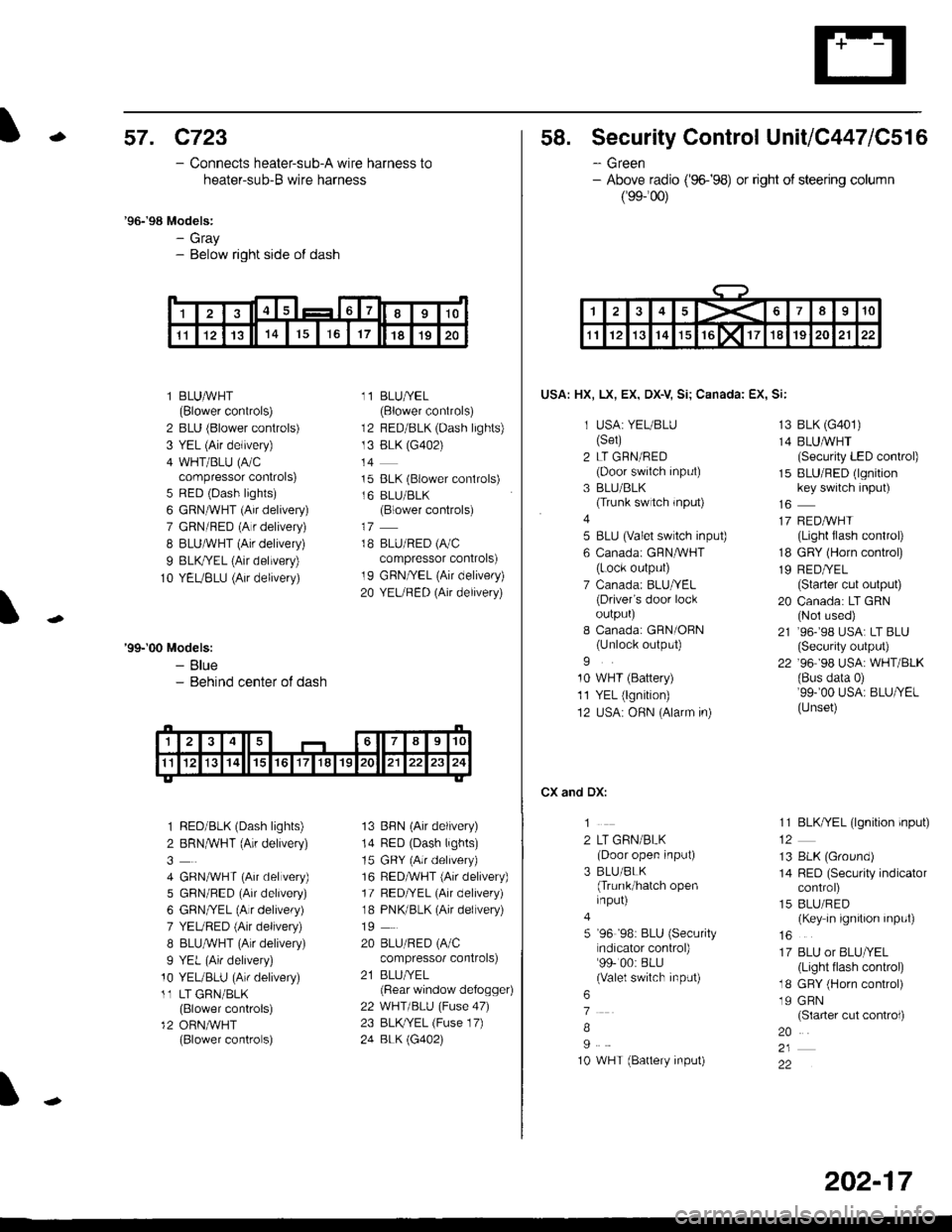
58. Security Control UnitiC447lC516
- Green- Above radio ('96-�98) or right of steering column
(99-'�00)
USA: HX, LX, EX, DX-V Si; Canada: EX, Si:
1 USA: YEUBLU(Set)
2 LT GRN/RED(Door swiich input)
3 BLU/BLK(Trunk switch rnput)
4
5 BLU (valet switch inpu0
6 Canadai GFNAVHT(Lock output)
7 Canada: BLU/YEL(Driver's door lockoulpurJ
I Canada: GRN/OBN(Unlock output)
9
10 WHT (Battery)
11 YEL (lgnition)
12 USA: OHN (Alarm in)
CX and DX:
1
2 LT GRN/BLK(Door open input)
3 BLU/BLK(Trunk/hatch openinput)
5 '96 '98: BLU (Security
ndicator control)99- 00: BLU(Valel switch input)
6
7
B
I
10 WHT (Battery input)
13 BLK (G401)
14 BLUMHT(Security LED conkol)
15 BLU/RED (lgnitionkey switch input)
17 REDAVHI(Light flash control)
18 GRY (Horn conkol)
19 RED/YEL(Starter cut output)
20 Canada: LT GRN(Nol used)
21 ,96-,98 USA: LT BLU(Security output)
22 '96 98 USA: WHT/BLK(Bus data 0)'99-'00 USA: BLU/YEL(Unset)
11 BLK/YEL (lgnition input)
13 BLK (Ground)
14 RED (Security indicatorcontrol)
15 BLU/RED(Key in ignition input)
16
17 BLU or BLU/YEL(Light tlash control)
18 GRY (Horn control)
19 GRN(Slarter cut control)
20
22
1><678910
1112131415rGlxllT1819202122
202-17
Page 2131 of 2189
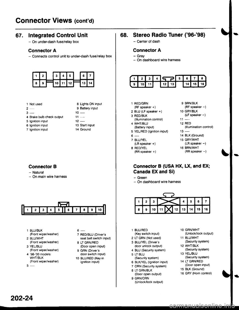
Gonnector Views (cont'd)
67. Integrated Control Unit
- On underdash fuse/relay box
Connector A
- Connects control unit to under-dash fuse/relay box
1 Not used
4 Erake bulb check output
5 lgnition input
6 lgnition input
7 lgnjtion input
Connectol B
- Natural- On main wire harness
l BLU/BLK
{Front wiper/washer)
2 BLUA/VHT(Front wiper/washe0
3 YEUBLU(Front wiper/washer)
4 '98-'00 models:WHT/BLK(Front wiper/washer)
8 Lights ON input
9 Battery input
11 _
13 Start input
14 Ground
7 RED/BLU (Driver's
seat b€lt switch input)
8 LT GRN/RED(Door open input)
I GRN (Oriver's
door switch input)'t0 BLU/RED (Key inignition input)
202-24
68. Stereo Radio Tuner ('96-'98)
- Center ot dash
Connector A
- Gray- On dashboard wire harness
1 RED/GRN(RF speaker +)
2 BLU (LF speaker +)
3 RED/BLK(lllumination control)
4 WHT/BLU(Battery input)
5 YEURED (lgnition input)
6-
7 BLU/YEL(LR speaker +)
8 RED/TEL(RR speaker +)
9 BRN/BLK(RF speaker -)
1O GRY/BLK(LF speaker -)
12 RED(lllumination control)
14 BLK (Ground)
15 GFY,4/VHT(LR speaker -)
16 BRNAVHT(RR speaker -)
Connector B (USA HX, UX, and EX;
Canada EX and Si)
- Green- On dashboard wire harness
l BLU/RED(Key switch input)
2 LT GRN (Not used)
3 BLU/'EL (Drivels
door unlock output)
4 BLU (Security system)
5 LT BLU
{Security system)
6 BLIVYEL (lgnition input)
7 ORN (Security system)
8 LT GRN/BLK(Door open output)
9 GRN/ORN(Unlock/lock output)
1O GRNAVHT(Unlock/lock output)
1 1 BLU/WHT(Security system)
'2 WHT/BLK(Security system)
13 YEUBLU(Security system)
14 LT GRN/RED(Door open input)
15 BLK (Ground)
16 GRY (Horn conkol)
Page 2140 of 2189
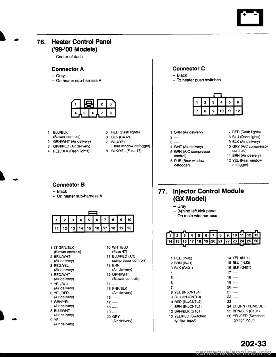
76. Heater Control Panel
('99100 Models)
- Center of dash
Conneclor A
- Gray- On heater sub-harness A
BLUi BLK(Blower controls)
GRNAVHT (Air delivery)
GRN/RED (Air delivery)
RED/BLK (Dash lights)
Connector B
- Black- On heater sub-harness A
7
8
1
4
RED (Dash lights)
BLK (G402)
BLUfYEL(Rear window defogg€0
BLK,TYEL (Fuse 17)
\
)
1 LT GRN/BLK(Blower controls)
2 BRN,A/VHT(Air delivery)
(Air delivery)
4 REDA/VHT(Air delivery)
5 YEUBLU(Air delivery)
6 YEURED(Air delivery)
7 GRN/YEL(Air delivery)
8 BLU,ryVHT(Air delivery)
9 YEL
{Air delivery)
1O WHT/BLU(Fuse 47)
11 BLU/RED WCcompressor controls)
12 BRN(Air delivery)
13 ORNAVHT(Blower controls)
14 -
15 PN(BLK(Air delivery)
16 _
19 _
20 GRY(Air delivery)
Connector C
- Black- To heater push switches
1 ORN (Air delivery)
2
4 WHT (Air delivery)
5 GRN (ry'C compressorcontrol)
6 PUR (Roar windowdelogge4
7 RED (Dash lights)
8 BLU (Dash lights)
I BLK (Air delivery)
10 GRY (Ay'C compressorcontrols)
1'1 BRN (Air delivery)
12 YEL (Rear window
defogge0
77. Injector control Module
(GX Model)
- Gray- Behind left kick panel- On main wire harness
1 RED (rNJ2)
2 BRN (rNJl )3 BLK (G401)
4_
8 YEL (TNJCNTL4)
9 BLU (TNJCNTL3)
1o RED (tNJCNTL2)
11 BRN 0NJCNTL1)12 BRN/BLK (G101)
13 YEURED (Switched
ignition input)
14 YEL (tNJ4)
15 BLU (rNJ3)
16 BLK (G401)
19 -
20-
21
24 LI GRN (INJMODE)
25 BRN/BLK (Gr 01)
26 YEURED (Switched
ignition input)
202-33