Page 1418 of 2189

Temperature Control
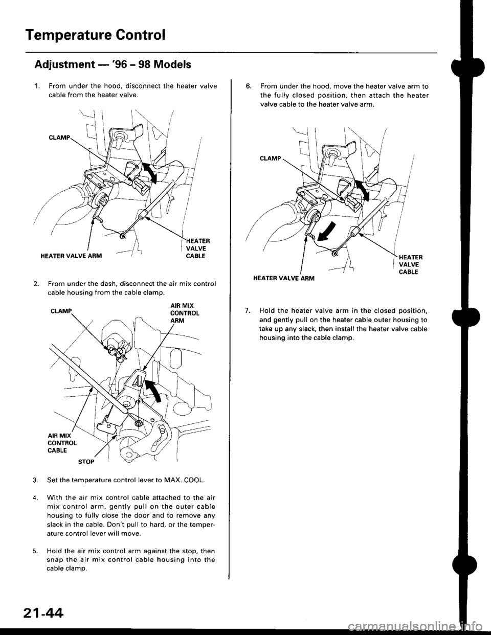
Adjustment -'96 - 98 Models
1. From under the hood, disconnect the heater valve
cable from the heater valve.
TERVALVECABLEHEATER VALVE ARM
2.From under the dash, disconnect the air mix control
cable housing from the cable clamp,
AIR MIXCONTROLARM
3.Set the temperature control lever to MAX. COOL.
With the air mix control cable attached to the air
mix control arm, gently pull on the outer cable
housing to fully close the door and to remove any
slack in the cable. Don't pullto hard, or the temper-
ature control lever will move.
Hold the air mix control arm against the stop. then
snap the air mix control cable housing into the
cable clamp.
21-44
6. From under the hood. move the heater valve arm to
the fully closed position. then attach the heater
valve cable to the heater valve arm.
7. Hold the heater valve arm in the closed position,
and gently pull on the heater cable outer housing to
take up any slack. then install the heater valve cable
housing into the cable clamp.
HEATER VALVE ARM
Page 1419 of 2189
Adjustment -'99 - 00 Models
1. From under the hood, open the cable clamp, then
disconnect the heater valve cable from the heater
valve arm.
From under the dash. disconnect the heater valve
cable housing from the cable clamp, and disconnect
the heater valve cable from the air mix control arm.
HEATER VALVE CABLE
Set the temperature control dial on MAX COOL with
the ignition switch ON {ll).
Attach the heater valve cable to the air mix control
arm as shown above. Hold the end of the heater
valve cable housing against the stop, then snap the
heater valve cable housing into the cable clamp.
HEATER VALVE ARM
5. From under the hood. turn the heater valve arm to
the fullv closed oosition as shown, and hold it,
Attach the heater valve cable to the heater valve
arm, and gently pull on the heater valve cable hous-
ing to take up any slack, then install the heater valve
cable housing into the cable clamp.
HEATER VALVE ARM
21-45
Page 1420 of 2189

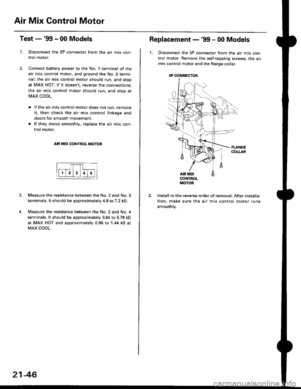
Air Mix Gontrol Motor
't.
Test -'99 - 00 Models
Disconnect the 5P connector from the air mix con-
trol motor.
Connect battery power to the No. 1 terminal of the
air mix control motor, and ground the No. 5 termi,
nal; the air mix control motor should run, and stop
at MAX HOT. lf it doesn't, reverse the connections;
the air mix control motor should run, and stop at
MAX COOL.
lf the air mix control motor does not run, remove
it, then check the air mix control linkage and
doors for smooth movement.
lf they move smoothly, replace the air mix con-
trol motor.
AIR MIX CONTROL MOTOR
Measure the resistance between the No.2 and No.3
terminals. lt should be approximately 4.8 to 7.2 kO.
Measure the resistance between the No. 2 and No. 4
terminals. lt should be approximately 3.84 to 5.76 kO
at MAX HOT and approximately 0.96 to 1.44 kO at
MAX COOL.
21-46
5P OONNECYOB
Replacement -'99 - 00 Models
1, Disconnect the 5P connector from the air mix con-
trol motor. Remove the self-tapping screws, the airmix control motor and the flange collar.
CONTROLMOTOR
Install in the reverse order of removal. After installa-
tion, make sure the air mix control motor runs
smoothly.
Page 1425 of 2189

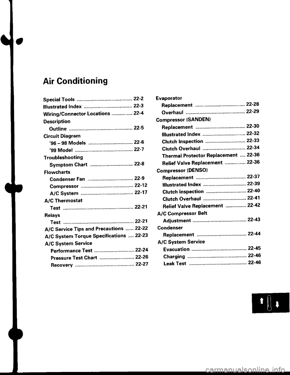
Air Conditioning
Speciaf Tools ......'.....' 22-2
f f f ustrated f ndex ......................... ".......' 22-3
Wiring/Connector Locations'.........'.... 22'4
Description
Outfine ............ .......22-s
Circuit Diagram
'96 - 98 Models ......"..........".......'.... 22-6
'99 Modef """""""' 22-7
Troubleshooting
Symptom Chart ".'......""................. 22-8
Flowcharts
Condenser Fan .........".................,..'. 22-9
Compressor .....""" 22-12
A/C System .........'.22'17
A/C Thermostat
Test ........'.......' """'22'21
Relays
Test ....."'......... ..""'22-21
A/C Service Tips and Precautions ......22-22
A/C System Torque Specifications '...22-23
A/C System Service
Performance Test ... '."......... ".... ....'..22-24
Pressure Test Chart .................. .... "' 22-26
Recovery ...".........," 22-27
Evaporator
Replacement .....",' 22'24
Overhauf .....-.....""' 22'29
Compressor {SANDEN}
Repf acement ......'.' 22-30
fffustrated fndex ......"..................'.... 22'32
Cf utch Inspection ......... "............ ...... 22-33
Clutch Overhau I ........................ ....... 22-34
Thermal Protector Replacement .... 22-36
Relief Valve Replacement ......'..."". 22-36
Compressor (DENSO)
Repfacement ..""',' 22-37
lf lustrated Index ............................... 22-39
Clutch lnspection ............."'...... "'.... 22-40
Cf utch Overhaul .....................'......... 22-41
Ref ief Valve Replacement'..'......"'.. 22-42
A/C Compressor Belt
Adiustment ............22'43
Condenser
Repfacement .......,,22'44
A/C System Service
Evacuation ...,,,.......22-45
Charging '..........--'..22'46
Leak rest """""""'22-46
Page 1427 of 2189
lllustrated Index
A/C PRESSURE SWITCHWhen the refrigerant pressure is below 200 kPa {2 0 kg7cm'�,
28 psi) due to ;frigerant leakage or above 3200 kPa (32 kgf/cm'�'
455 psi) due to refrigerant blockage, the lVC pressure swrtch
SERVICE VALVE
{LOW.PRESSURE SIDE)
EVAPORATORReplacement, page 22-28
Overhaul, page 22 29
Beplacement, Page 22'44
opens lhe circuit to ihe AVC switch and stops the air condilioning
to protect the comPressor'
RECEIVER/DRYER
COMPRESSORSANDENIReplacement, Page 22 30
CIutch Inspection, Page 22 33
Thermal Protector Inspection, page 22 33
Clutch Overhaul, Page 22'34
Thermal Protector Replacement, page 22 36
Refief Vafve Replacemenl, page 22'36
DENSO:Replacement, Page 22-37
Clutch Inspection, Page 22-40
Clutch Overhaul, Page 22_41
Relief Valve Replacement, page 22-42
A/C THERMOSTATTest, page 22 21
22-3
Page 1429 of 2189

Description
Outline
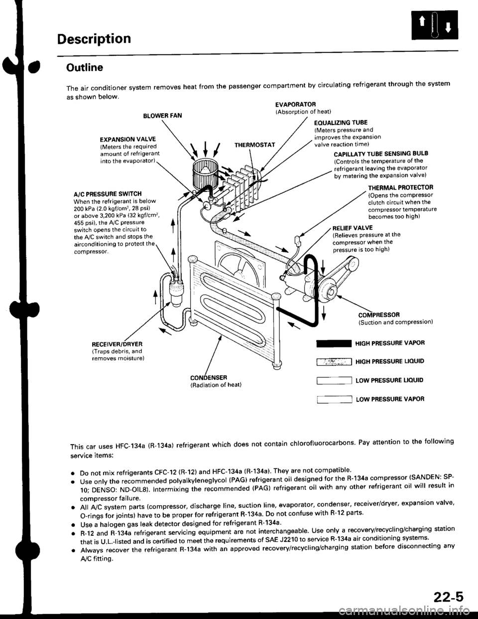
The air conditioner system removes heat from the passenger compartment by circulating refrigerant through the system
as shown below.
BLOWER FAN
EVAPORATOR(Absorption of heati
EOUALIZING TUBE(Meters pressure andimproves the expansionvalve reaction time)
into the evaporator)CAPILLATY TUBE SENSING BULB
lControls the temPerature of the
ref rigerant leaving the evaporator
by metering the expansion valve)
/\
THERMOSTAT
A/C PRESSURE SWITCH
When the refrigerant is below
200 kPa (2.0 kgtcm'�,28 Psi)or above 3,200 kPa 132 kgflcm',
455 psi), the Ay'C pressure
switch opens the circuit to
the A,/C switch and stops the
EXPANSION VALVE(Meters the requiredamount of refrigerant
airconditioning to Protect the
compressor.
RECEIVER/DRYER(Traps debris, andremoves morsturel
THERMAL PROTECTOR
{Opens the comPressorclutch circuit when the
compressor temPeraturebecomes too high)
RELIEF VALVE(Relieves pressure at the
compressor when thepressure is too high)
(Radiation of heat)
I
f-r-�-; I
(Suction and comPression,
HIGH PRESSURE VAPOR
HtGH PRESSUBE LIOUID
LOW PRESSURE LIOUID
This car uses HFC-134a (R-134a) refrigerant which does not contain chlorofluorocarbons Pay attention to the following
service items:
. Do not mix refrigerants CFC-12 (R-12) and HFC-134a (R-134a)' They are not compatible'
. Useonlythe recommended polyalkyieneglycol (PAG) refrigerant oil designedforthe R-134a compressor (SANDEN: SP-
10; DENSO: ND_OIL8). Intermixing ihe re-commended (pAG) refrigerant oil with any other refrigerant oil will result in
compressor failure.
. All A,,ic system parts {compressor, discharge line, suction line, evaporator, condenser, receiver/dryer, expansion valve'
O-rings for joints) have to be proper for refrigerant R- 134a Do not confuse with R-l2 parts'
. Use a halogen gas leak detector designed for refrigerant R-134a
. R-12 and R-134a refrigerant servacing equipment are not interchangeable. Use only a recovery/recycling/charging station
that is u,L.-listed and is certified to meet the requirements of sAE J2210 to service R-134a air conditioning systems'
. Always recover the refrigerant R-134a with an approved recovery/recycling/charging station before disconnecting any
A,/C fitting.
S]
22-5
Page 1434 of 2189
Troubleshooting
Condenser Fan (cont'd)
CONDENSER FAN RELAY 4P SOCKET
CONDENSEB FAN 2P CONNECTORWire side of female terminals
-=F_
l!.lI slx
@I
Check tor an opon in the wi.o:1. Disconnect the jumper wire.2. oisconnect the condenser tan2P connector.3. Check for continuity betweenthe No. 1 terminal of the con-denser fan relay 4P socket andthe No. 1 terminal of the con-denser fan 2P connector.
Rapair op6n in the wirs bgtwconthe condcnsor tan rclay and thecondgnlar fan.
ls there continuity?
Check to. en open in the wire:Check for continuity between theNo. 2 terminal ot the condenserfan 2P connector and bodyground.
Check Ior rn opon in th6 wirebctwoen the condcnser tan andbody ground, lf iho wirc ii OK,chcck for poor ground at G751.
ls there continuity?
Replaco the condense. fan motor.
22-10
Page 1435 of 2189
Check the diode:1. Disconnect the iumPer wire
2. Remove the A/C diode from
the under hood fuse/relaY box
3. Check for current flow in both
directions between the A and
B terminals.
ls there current flow in onlY
one direction?
Chock for an open in the wire:
1. Turn the ignition switch ON(ll).
2. Measure the voltage between
the No. 2 terminal of the AJC
diode 2P socket and body
ground.
Repair opon in the wire betwe€n
the No. 17 luse and the A/c
diode.ls there battery voltage?
B()-=iFA
A/C DIOOE 2P SOCKET