2000 HONDA CIVIC Ground
[x] Cancel search: GroundPage 1798 of 2189
Troubleshooting
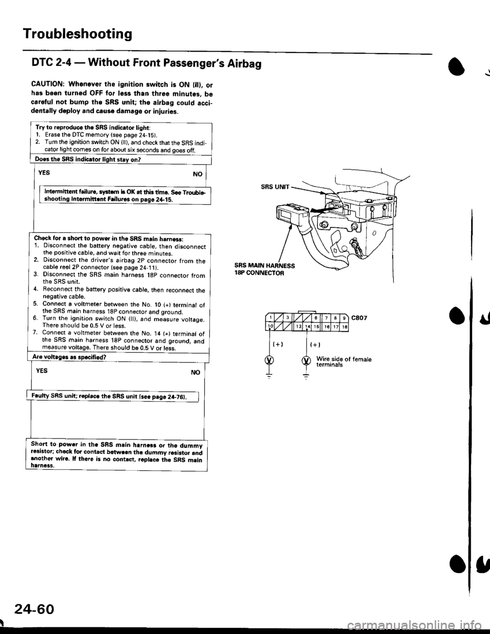
DTC 2-4 - Without Front Passenger's Airbag
CAUTION: Whenever the ignition switch is ON 0l). orhas been turned OFF for lsss lhan three minutes. becaretul not bump the SRS unit; the airbag could acci-dentally doploy and causo damage or iniuries.
Try to r€produc€ tho SRS indic.to. light:1. Erase the DTC memory (see page 24,15).2. Turn the ignition switch ON (ll), and check that the SRS indi-cator light comes on for about six seconds and go€s off.
Do€rthe SRS indicrtor light stay on?
NOrEs
lntormitteit t ilur., iyst m b OK at thb tim6. Sle Troubleshooling Intdmitt.nt Frilu.os on pag6 2+lS.
Check for a short to power in the SRS main h.rna3s:1. Disconnect the baftery negative cable, then disconnectthe positive cable, and wait for three minutes.2. Dlsconnect the driver's airbag 2p connector from thecable reel 2P connector (see page 24,11).3. Dlsconnect the SRS main harness l8p connector tromthe SRS unit.4. Beconnect the battory positiv€ cable, then reconnect thenegative cable.5. Connect a voltmeter between the No. lO (+) terminal ofthe SFS main hsrness 18P connector and qround.6. Turn the ignition switch ON {ll), and me-asure voltage.There should be 0.5 V or less.7. Connect a voltmeter between the No. 14 (+) terminal ofthe SRS main harness 18P connoctor and ground, andmeasure voltage. There should be 0.5 V or less.
A.e voltage. .3 spocifi.d?
YES NO
F.ulty SRS uniC .epla"" tl,. SnS unn l""" p"g" 2+7O:_l
Short to pow.r in tha SRS mlin harnc$ or tho dummyr*istor; chock lor contact bctwcen th. dummy r6ai3to. rndrnother wiro. lf there is no contrct, rcphcc the SRS msinhame3s.
SBS UNIT
SRS MAIN18P CONNECTOR
24-60
I
Page 1799 of 2189
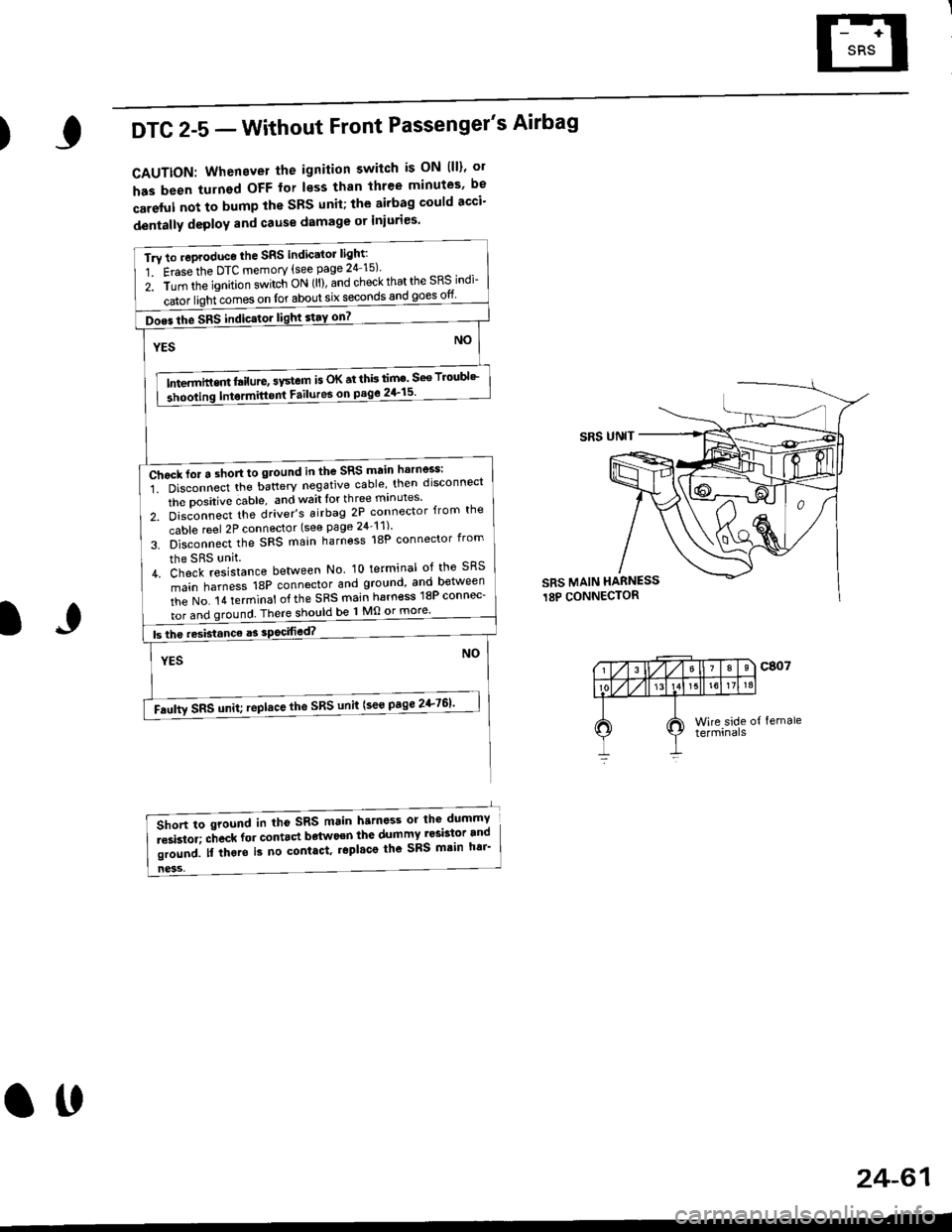
)DTC 2-5 - Without Front Passenger's Airbag
CAUTTON: Whenever the ignition switch is ON lll)' ol
has been turnsd OFF for less than three minutes' be
careful not to bump the SBS unit; the airbag could acci'
dentally deploY and Gause damage or iniuries'
Tru to .oproduce the SRS indic'tor light:
1 Erasethe DTC memory {see page 24 15)'
z. irin tfie ignition s.itch ON (ll), and check that the SRS indi-
iatoi ligiricomes on for about six seconOs and goes otf
Does the SRS indic.tor light stay on7 |
NOYES
tn---t",-in"m l"itrt", "v"tem is oK at thb lim' seo Troubl'-
3hooling Intormitt6nt Failures on pago 2+15'
ffih",n"""'i. oi""onn""t ttte u"tt"ry negative cable' then disconnect
the Dositive dable, and wait lor th ree mrnutes'
z. 6i"J-"""a tt'" driver's airbag 2P connector {from the
cable reel 2P connector (see page 24_11)'
s. b]""onn""t,f'" SFS main harness 18P connector from
the SRS unit.
L di"lfi""i"on." between No lo terminal of the sRS
main harness 18P connector and ground and between
iie t'lo. t a terminat of the SRS main harn€ss 18P connec-
I tor and ground There should be 1 Mo or more'
I btheresistanceasso444g14�._���._��
NOYES
-Faulty sRs unit; ,epltce the sRs unit (see page 2+761'
SRS UNIT
SRS MAIN HARNESS
18P CONNECTOR
IJ
ness,
6lort to sround in tho sRS main harness or the dummY
i""i"toi; "-ft""* fot "ont.ct bdtwo€n the dumTI Iesbt9r.and
li"r"J. n irt"t" is no contact. r6pl'co the sRs mtin h6i'
24-61
ott
Page 1800 of 2189
Troubleshooting
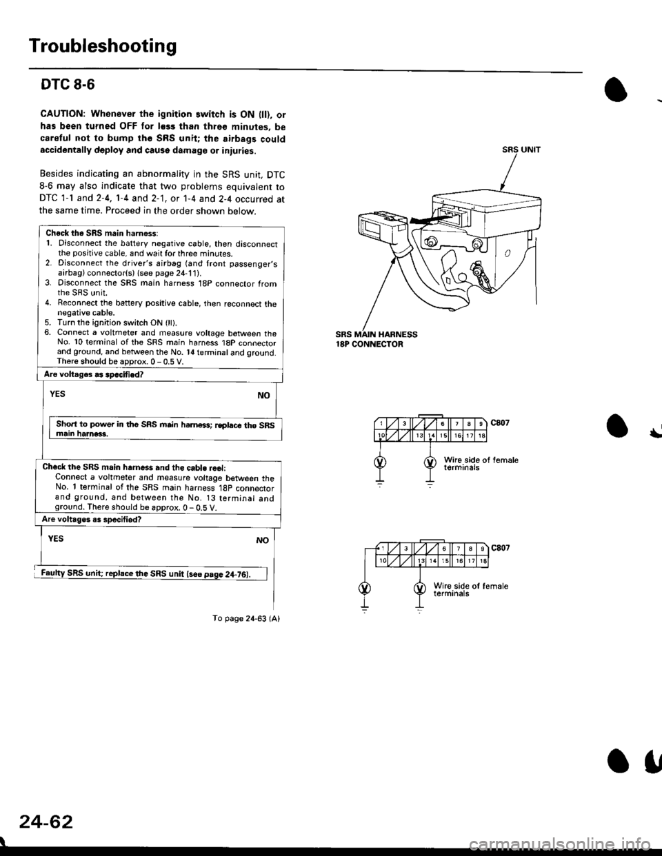
DTC 8-6
CAUTION: Whonover the ignition switch is ON lll), or
has been turned OFF for less than thro€ minutes, be
careful not to bump th6 SRS unit; the airbags couldaccidentally deploy and cause damage or iniuries.
Besides indicating an abnormality in the SRS unit, DTC
8-6 may also indicate that two problems equivalent to
DTC 1-l and 2-4, 1-4 and 2-1, ot 1-4 and 2-4 occurred at
the same time. Proceed in the order shown below.
SRS MAIN HARNESS18P CONNECTOR
\
24-62
Check th. SRS main harn6$:1. Disconnect the battery negative cable, then disconnectthe positive cable, and wait for three minutes.2. Disconnect the driver's airbag (and front passenger,sairbag) connector(s) {see page 21-111.3. Disconnect the SRS main harness 18P connector fromrhe sRS unit.4. Reconnect the battery positive cable, then reconnect thenegative cable.5. Turn the ignition switch ON (ll).6, Connect a voltmeter and measure voltage botween theNo. 10 terminal of the SRS main harness 1BP connectorand ground, and betlveen the No. l{ terminal and qround.Th6re should be aoDrox. 0 - 0.5 V.
Aro voltages as spacified?
NOYES
Sho.t to power in tho SRS mrin hamoss; rsplace th6 SRSmain haanac3.
Chacl the SRS main hrrne*s and the cabl. reel:Connect a voltmeter and measure voltage between theNo. 1 terminal of the SRS main harness 18p connectorand ground, and between the No. 13 terminal andground. There should be approx. 0 - 0.5 V.
Are voltages o3 specilied?
YES
SRS unit; replace the SRS unit lse6 page 2+76).
NO
To page 24-63 (A)
o1,
Page 1801 of 2189
,)
IJ
t,
From page 24'62 (A)
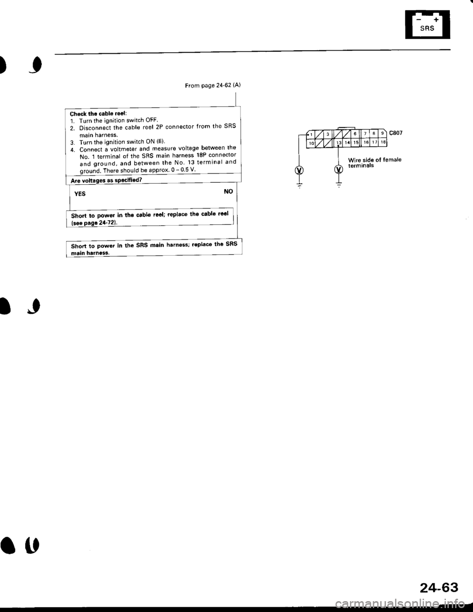
Check the cable reel:
1. Turn the ignition switch OFF
2. Disconneit the cable reel 2P connector from the SRS
maln harness,
3. Turn the ignition switch ON {ll}
4. Connect a voltmeter and measure voltage between the
No. 1 terminal of the SRS main harness 18P connector
and ground, and between the No 13 terminal and
ground. There should be approx. 0 - 0.5 V'
Are vohtg6 as specifi"dT -
YESNO
Short to powor in the cabto reel; replace thg cable rool
(see page 24'721.
Short to powet in the SRS main h.rness; replace the SRS
main harness.
24-63
Page 1802 of 2189
Troubleshooting
DTC 9-2
CAUTION: Whenever the ignition switch is ON 0l), ofhas been turned OFF lor lass than three minutes, becareful not to bump the SRS unit; the airbag(s) couldaccidentally deploy lnd caqse damage or iniuries.
Check the tu.c:1. Turn the ignition switch OFF.2. Check for blown No. 23 (10 A) fuse in the under,dashfuse/relay box.
Replace the tuse. Turn the ignition switch ON lll) , and checkthat the fuse doesn't blow.
Th6 problem hs3 disappe.rod, TGt-dJiv€ the vehiclo and3ee Troublerhooting Intermiftcnt Failuro3 on paqo 2l-15.
Check tol short to ground betwe.n tho unde.-da3h fus./r.ley box and the SRS unit.1. Turn the ignition switch OFF.2. Disconnect the baftery negative cable, then disconnectthe positive cable, and waittorthree minutes.3. Disconnect the driver's (and front passenger,s) airbagconnector(s) (see page 24-11).4. Disconnect the SRS main harness 1gp connector fromthe sRs unit.5. Check resistance between the No. 3 terminal of the SRSmarn harness 18P connector and ground,There should be 1 MO or more.
Feufty SRS unh; rcphce the SRS unit lsee pag.2+761.
(A)To page 24-65
To page 24-65
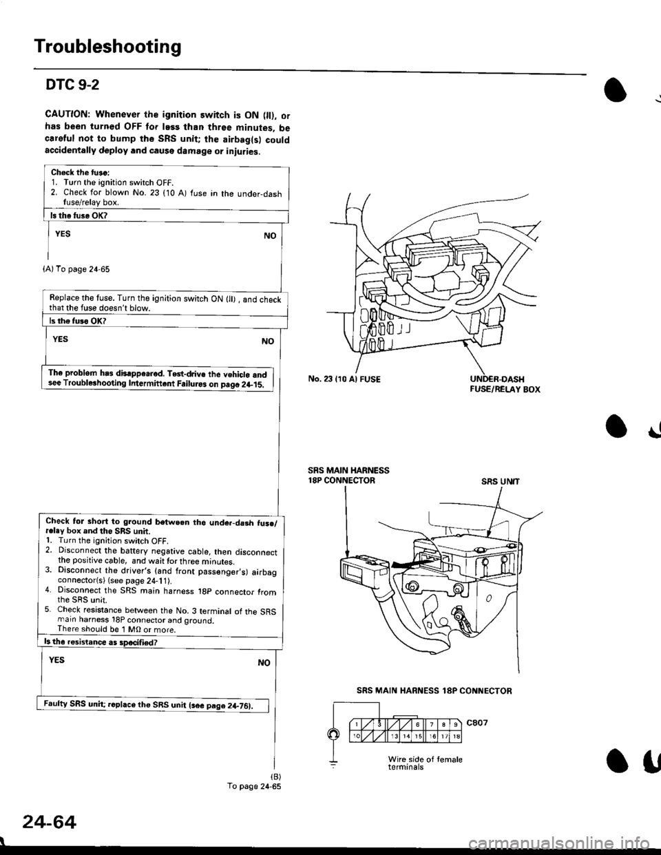
No. 23 lr0 Al FUSEFUSE/RELAY BOX
!
SRS MAIN HARNESS18P CONNECTORSRS UN'T
24-64
I
SRS MAIN HARNESS 18P CONNECTOR
Otf
Page 1803 of 2189
)
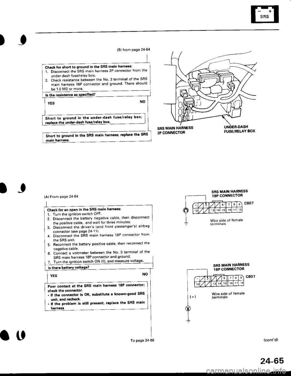
FUSE/BELAY BOX
Chcck for an op€n in th6 SRS main harness:
1. Turn the ignition switch OFF.
2. Disconne;t the battery negative cable, then disconnect
the positive cable, and wait for three minutes'
3. Disconnect tho driver's (and front passenger's) airbag
connector (see Page 24'11).
4. Disconnect the SRS main harness 18P connector from
the SRS unit
5. Reconnect the battery positive cable, then reconnect the
neoative cable.
6. Co-nnect a voltmeter betlveen the No 3 terminal ol the
SFS main harness 18P connector and ground'
7. Turn theswitch ON (ll), and m€asure
(cont'd)
(B) from page 24-64
Check tor ahort to ground in the SRS main harn$s:
1. Disconnect the SRS main harness 2P connector from the
under-dash fuse/relaY box.
2. Check resistance between the No. 3 terminal of the SRS
main harness 18P connector and ground There should
be 1.0 M0 or more.
ls the re3istance a3 specified? -
NOYES
Short to giound in tho undot-drlh lut'/rol'y box;
replace the undel-da3h fusgtgEl!9l--------.-
Short to ground in tho SRS m.in harn$s; ropleco the SRS
main harness.
(AlFrom page 24'64
Poor contact at the SRS main harnoss 18P connoctor;
check lho connoctor.. ll the connector k OK, sub3titute r known'good SRS
unh. and recheck. lf the problom is slill present, lepl.ce the SRS main
To page 24-66
SRS MAIN HARNESS18P CONNECTOR
o0
24-65
Page 1809 of 2189
E-
)I
Connect a 12 volt battery to the tool:
. lf the green light on the tool comes on, the aar-
bag igniter circuit is defective and cannot deploy
the airbag. Go to Damaged Airbag Special
Procedure.
. lf the red light on the tool comes on, the airbag is
ready to be deployed.
Push the tool's deployment switch. The airbag
should deploY (deployment is both highly audible
and visible; a loud noise and rapid inflation of the
bag, followed by slow deflation).
. lf the airbags deploy and the green light on the
tool comes on. continue with this procedure.
. l{ an airbag doesn't deploy, yet the green light
comes ON, its igniter is defective. Go to Dam-
aged Airbag Special Procedure.
!!@ During doployment, the airbag sssom'
bly can become hot enough to buln you. Wait thir'
ty minutes aftsr deployment belore touching tho
assembly.
Dispose of the complete airbag assembly. No part
of it can be reused. Place it in a sturdy plastic bag,
and seal it securelY,
CAUTION:
. Wear a fsce shield and gloves when handling a
deployed airbag.
. Wash your hands and rinse them well with
wat6r after handling. deployed airbag.
t('
24-71
7.
AIRAAG
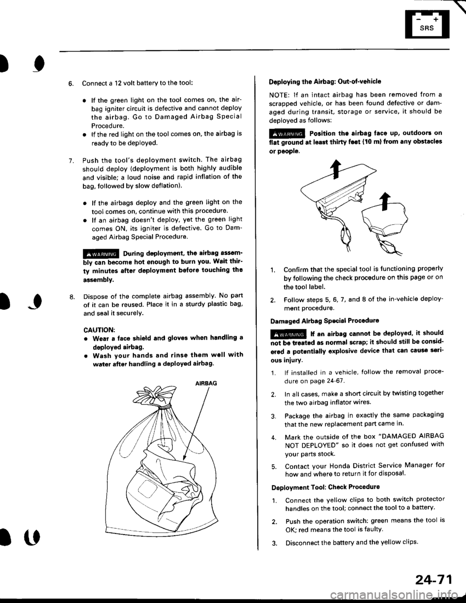
Doploying th6 Airbag: Out-of-vehicle
NOTE: lf an intact airbag has been removed from a
scrapped vehicle. or has been found defective or dam-
aged during transit, storage or service, it should be
deployed as follows:
@ Po3ition the airbag laca up, outdoors on
flat ground at lsast thirty f€€t (t0 ml from any obstacles
or people.
1. Confirm that the special tool is tunctioning properly
by following the check procedure on this page or on
the tool label.
2. Follow steps 5, 6, 7, and I of the in-vehicle deploy-
menl Drocequre.
Damaged Airbag Spacial Procedure
!@ r an airb.g cannot be deployed, it should
iiiTi-treatcd as normal scrap; il should still be consid-
srsd a potontially oxplosive device that can cau3o ssti-
ous iniury.
1. lf installed in a vehicle, lollow the removal proce-
dure on page 24-67.
2. In all cases. make a short circuit by twisting together
the two airbag inflator wires.
3. Package the airbag in exactly the same packaging
that the new replacement part came in.
4. Mark the outside of the box "DAMAGED AIRBAG
NOT DEPLOYED" so it does not get confused with
your Parts stock.
5. Contact your Honda District Service Manager for
how and where to return it for disposal.
Deployment Tool: Check Procedur€
1. Connect the yellow clips to both switch protector
handles on the tool; connect the tool to a battery.
2. Push the operation switch: green means the tool is
OK: red means the tool is faulty
3. Disconnect the battery and the yellow clips.
Page 1817 of 2189

Contents
How to Use This Manual ICircuit Schematics (see Circuit Index)Fuse/Relaylnformation 6Ground-to-Componentslndex 6-6ComponentLocationPhotooraohs 201Conriector Views 202
Circuit Index
Accessory power socket 155Air conditionerAir delivery'96198 models 61'99-'00 models 61-2Blower controls'96198 models 60'99100 models 60-1Compressor controls 62Fans 63Anti-lock brake system (ABS) 44A/T gear position indicatorCVT 89All except CVT 89-1Automatic transmission controlsAll '96-'98 models except CVT and GX 39All '99100 models except CVT 39-8All GX models 39-8'96-'�98 CVT 39-4'99100 cw 39-12Back-up lightsCoupe and Sedan 110Hatchback l'10-1Brake lightsAll Coupes and'96-'98 Sedans 110-15'99-'00 Sedans 110-16Hatchback 110-17Brake system indicator light'96198 models 7'1'99100 models 71-1Ceiling light 114-3Charging system 22Condenser fan 63Console lights 114Cruise control 34Dash lights 114Daytime running lights 110- 13Engine coolant temperature gauge 81-1Fog lights 110-10Front parking lights 110-2Fuel gauge 81-1Fuse/relay boxUnder-dash 6Under-hood 6-4Underhood ABS 6-3Gauges 81Ground distribution 14Ground-to-Componentslndex 6-6Hazard warning lightsAll except '99100 Sedans 110-6'99100 Sedans 110-8Headlights 110-12Headlight switch 100Heater - See Air ConditionerHorn'96197 models 40'98 model 40-1'99100 models 40-2lgnition key reminder 73lgnition systemAll '96198 models except Dl685 20All '99100 models except D16Y5 with Mn 2O-2All D1685 engines 20-2'99-'00 D 16Y5 with M/T 20
lndicators 80Integrated control unit 70lnterlock systemAll except'96J98 CVT 138'96198CVT 138-1License plate lightsAll Coupes and '96-'98 Sedans I l0-3'99100 Sedans 1 10-4Hatchback 110-5Low fuel indicator light 74Moonrool'96197 models |22'98-'00 models 122-1Odometer 81Oil pressure indicator light 80-3Power distributionBattery to ignition switch, fuses, and relaysFuses to relays and components 10-2Power door locksAll models without keyless entry 130'96-'98 models with keyless entry 130-2'99100 models with keyless entry 130-12Power mirrorsWithout detogger 141With defogger '141-2
Power windows 120Programmed fuel injection system (PGNr-Fl)All '96-98 models except D1685 23All '99-'00 models except D16Y5with M/T and D1685 24All D1685 engines 25'99100 D16Y5 with M/T 23Radiator fan 63Rear window defogger'96-,98 models 64'99100 models 64-1Seat belt reminder 73Security system'96.'98 USA HX, LX, EX 133'96-'98 Canada EX, Si 133'99TOO USA HX, LX, EX, DX.V Si 133-4'99100 Canada EX, Si 133-4All CX and DX models 133-8Speedometer 81Starting systemA./T (All except Dl685) 21A"/r (D16Bs) 21-1Manualtransmission 21-2Slereo sound system 150Supplemental rastraint system (SRS) 47Tachometer 81TailliqhtsAllboupes and'96-'98 Sedans 110-3'99100 Sedans 1 10-4Hatchback 110-5Trunk light 114-3Turn signal lightsAll except'99100 Sedans 110-6'99-'00 Sedans 1 10-8Vehicle speed sensor (VSS) 33Wiper/washerFront 91Rear 92
10