Page 1559 of 2189
lgnition Switch
4.
Test
SRS components are located in this area Review the
SRS component locations. precautions. and procedures
in the SRS section {24} before performing repairs or ser-
1. i/ake sure you have the anti-theft code for the
radio, then write down the frequencies for the
radio's preset buttons ('99 - 00 models).
2. Disconnect the battery negative cable.
3. Remove the driver's dashboard lower cover and
knee bolster (see section 20).
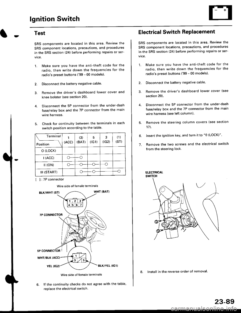
Disconnect the 5P connector from the under dash
fuse/relay box and the 7P connector from the main
wire harness.
Check for continuity between the terminals in each
switch position according to the table.
I I :7P connector
Wire side ot female terminals
BLK/WHT {STIWHT IBAT}
7P CONNECTOR
WHT/BLK
YEL (IG2}BLK/YEL {IG1)
Wire side of female terminals
6. lf the continuity checks do not agree with the table,
replace the electrical switch.
Terminal
Position
1
(ACC)
(3)
(BAT)
5
{tG1) G2)
(1)
(sr)
o (LocK)
| (ACC)o--o
l (oN)o-o
III (START)o--o
1.
Electrical Switch RePlacement
SRS components are located in this area. Review the
SRS component locations, precautions, and procedures
in the SRS section \24) belore performing repairs or ser-
vtce.
1. Make sure you have the anti-theft code for the
radio, then write down the frequencies for the
radio's preset buttons {'99 - 00 modelsl.
2. Disconnect the battery negatlve cable.
3. Remove the driver's dashboard lower cover {see
section 20).
Disconnect the 5P connector from the under-dash
fuse/relay box and the 7P connector from the main
wire harness (see left column).
Remove the steering column covers {see section
11t.
lnsert the ignition key, and turn it to "0 {LOCK)".
Remove the two screws and the electrical switch
from the steering lock.
ELECTRICALswtTcH
8. Install in the reverse order of removal.
23-a9
Page 1560 of 2189
lgnition Switch
Steering Lock Replacement
SRS components are located in this area. Review theSRS component locations. precautions, and procedures
in the SRS section (24) before performing repairs or ser-vtce.
Remove:
LMake sure you have the anti-theft code for theradio, then wire down the frequencies for theradio's preset buttons ('99 - 00 models).
Disconnect the battery negative cable.
Remove the driver's dashboard lower cover andknee bolster (see section 20).
Disconnect the 5P connector from the under-dash
fuse/relay box and the 7P connector from the mainwire harness (see previous page).
Remove the steering column covers, then removethe mounting bolts and nuts from the steering col-umn (see section l7).
Lower the steering column assembly,
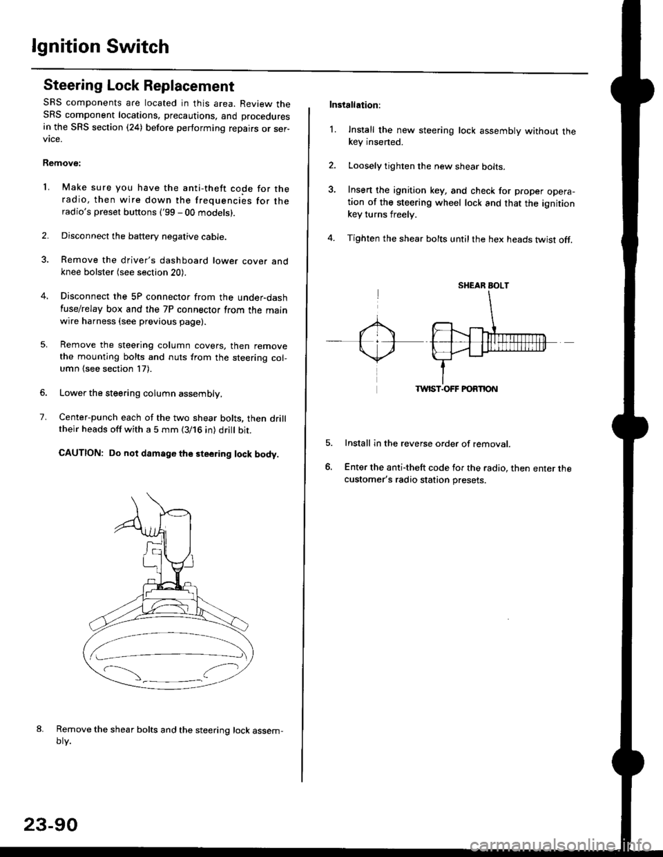
Center-punch each of the two shear bolts, then drilltheir heads off with a 5 mm (3/16 in) dritt bit.
CAUTION: Do not damago the steering lock body.
Remove the shear bolts and the steering lock assem,oty.
2.
1.
23-90
Installation:
l. Install the new steering lock assembly without thekey insened.
Loosely tighten the new shear bolts-
Insert the ignition key, and check for proper opera-tion of the steering wheel lock and that the ignitionkey turns freely.
Tighten the shear bolts untilthe hex heads twist off.
TWIST.OFF FORTION
Install in the reverse order of removar.
Enter the anti-theft code for the radio, then enter thecustomer's radio station presets.
sr{€aR SroLT
Page 1617 of 2189
Key Interlock Solenoid Test
Remove the driver's dashboard lower cover and
knee bolster (see section 20)
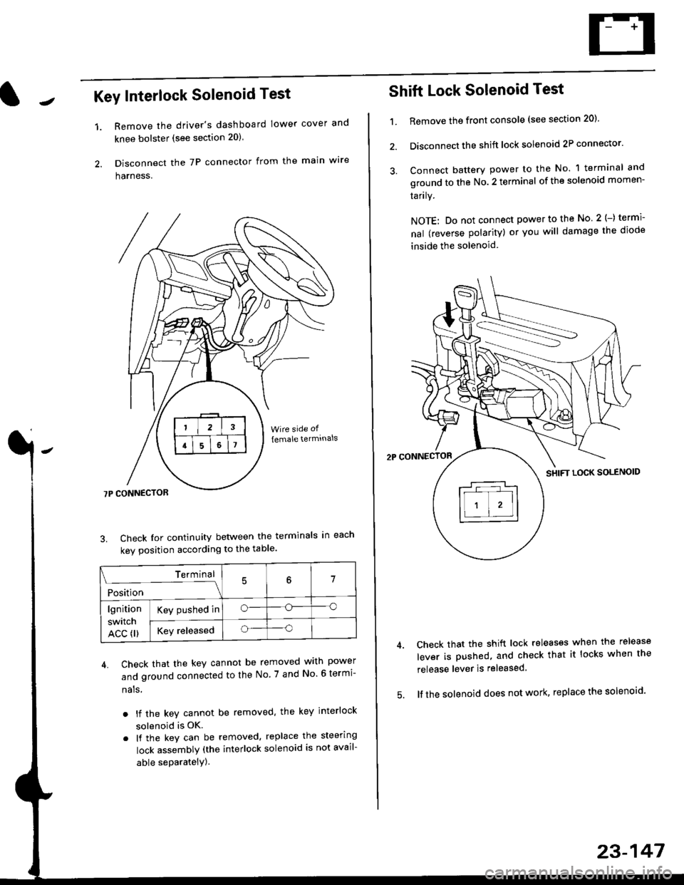
Disconnect the 7P connector from the main w're
harness.
3. Check Ior continuity between the terminals in each
kev oosition according to the table'
4. Check that the key cannot be removed with power
and ground connected to the No. 7 and No 6 termi-
nals
. lf the key cannot be removed. the key interlock
solenoid is OK.
. lf the key can be removed, replace the steering
lock assembly (the interlock solenoid is not avail-
able seParatelY).
1.
Terminal
i*i,r"
- - --\7
lgnition
switch
ACC fl)
Key pushed ino--o
Key releasedo--o
Shift Lock Solenoid Test
't.Remove ths front console (see section 20)'
Disconnect the shift lock solenoid 2P connector'
Connect battery power to the No. 1 terminal and
ground to the No. 2 terminal of the solenoid momen-
Iarrry.
NOTE: Do not connect power to the No 2(-) termi-
nal (reverse polarity) or you will damage the diode
inside the solenoid
Check that the shift lock releases when the release
lever is pushed, and check that it locks when the
release lever is released
lf the solenoid does not work, replace the solenoid'
23-147
Page 1827 of 2189
How To Use This Manual
Symbols
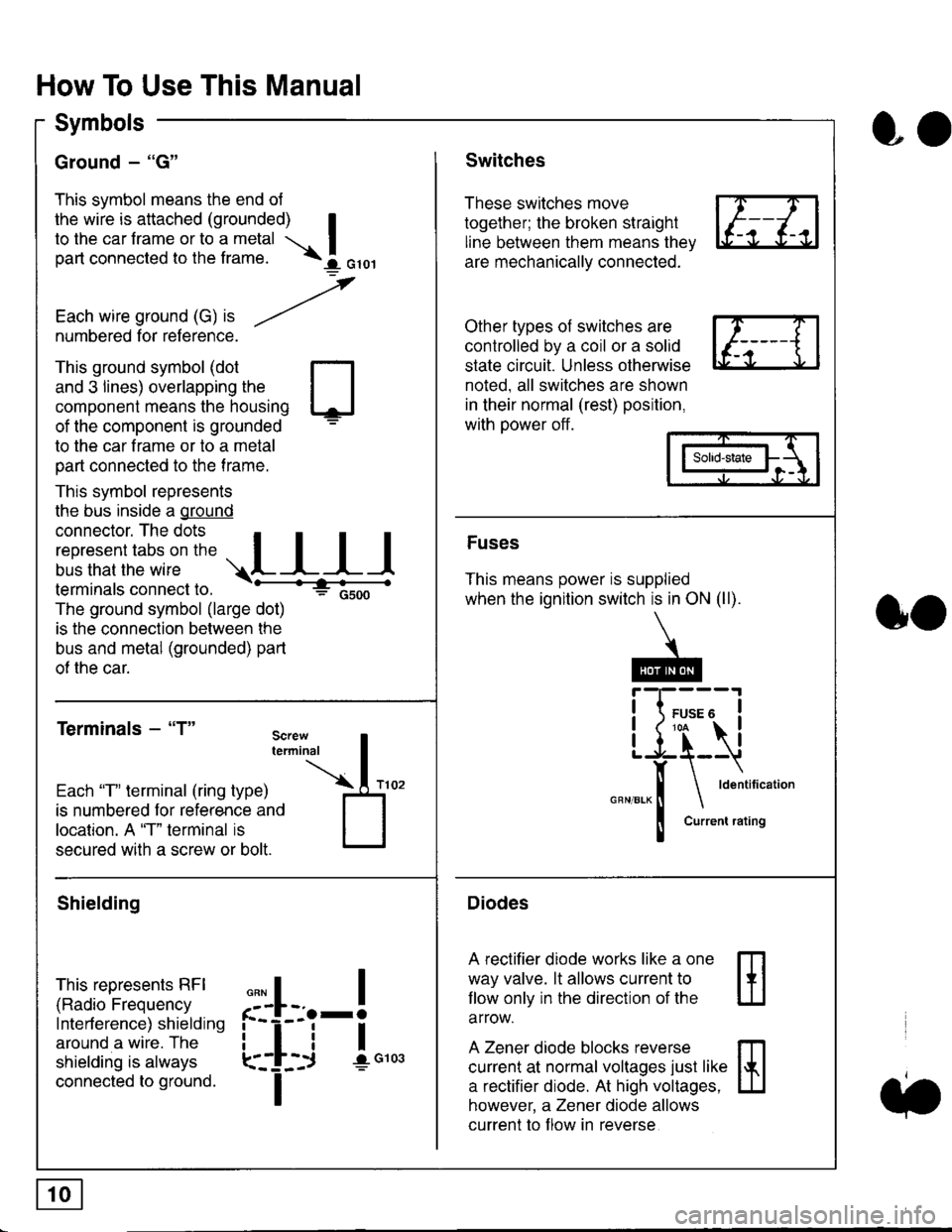
Ground - "G"
This symbol means the end ol
the wire is attached (grounded) Ito the car frame or to a metal I
part connected to the frame. \i oro,|
-t'
Each wire ground (G) it --/
numbered for reference.
oo
Switches
These switches move
together; the broken straight
line between them means the,
are mechanically connected.
Other types of switches are
controlled by a coil or a solid
state circuit. Unless otherwise
noted. all switches are shown
in their normal (rest) position,
with power off.
This ground symbol (dot
and 3 lines) overlapping the
component means the housing
of the component is grounded
to the car frame or to a metal
part connected to the frame.
This symbol represents
the bus inside a ground
connector. The dots I
i:l*,':1,'^:*,:"
;"
r"L I I I
terminals connect to.
The ground symbol (large dot)
is the connection between the
bus and metal (grounded) part
of the car.
Terminals - "T"
ffi
ffi
Solid-state
Fuses
This means power is supplied
when the ignition switch is in ON (ll).
Current rating
Diodes
A rectifier diode works like a one
way valve. lt allows current to
llow only in the direction of the
arrow.
A Zener diode blocks reverse
current at normal voltages just like
a rectifier diode. At high voltages.
however, a Zener diode allows
current to f low in reverse
oo
Each "T" lerminal (ring type)
is numbered for reference and
location. A "T" terminal is
secured with a screw or bolt.
Shielding
This represents RFI
(Radio Frequency
Interference) shielding
around a wire. The
shielding is always
connected to ground.
f--l;j-i",..
I
,,,,
T
Page 1976 of 2189
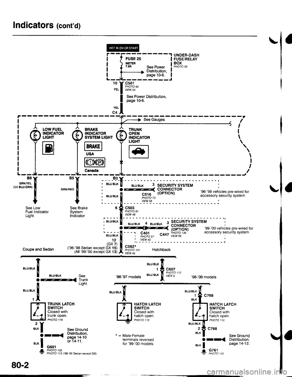
Indicators (cont'd)
I
I
I
I
't0 t
YEL
YEL
FUSE 2sUETER7.54
.I UNDER-DASH
IFUSE/RELAY
! F,gI".,I
IJ
See PowerDistribution,page 10€.
@f,*+* @sv#ftn* G)ffig^,", t
I
S€e Pow€r Distribution,page 10-6.
?-(: i#i',du), c401 ^t,a PHOfO 1J6I pHOfO 57 v"r vlEW 58
'99- 00 vehicles pre-wired foraccessory security system
I :7 r----r -7 ucHr \
i llEl lH lt*l
'.,
| | i r{rN/,6n1I I I l\y
//l I t
t--J-------Lfe---t---- ---JB8Y BsY B3YB8Y BsY -___B_3_Y_
,"' sfilJi:, i "*,*" i ;
""'"'*
! - "*-i
F"EIi,6HiJttr" so. sa venricres pre_w reo ror
I | : ".u,"r" ! ii|ot$,, accessory securrtv svstem
+ + l-----il------"rl';r'- ------------i
i "Lu,"r" ! rc;1rg (oPrroN) """"";:"J; !H;fi;"";Jt"'
l_____ll_ ____-v'_E\s!- __________-_i
o A csoeI PsOrO 6t
,----l-'':y:-
i """'^ I ".u"." -4 ELueLx 9 3B"rU"?'JYSJtttt :
See Low See Brake 6 Zl C503Fuel lndicator System ]l Paoro o'Light Inbicator ,____l_'':Y":-, BLU BLK ll _... _.._ q SECURTW SYSTEM, I BLU'BLK .. BLU/8!K : nourpcrrip
Coupe and Sedan
'96197 models
"ar,"a^ fi
'tg::1",,,
BLU/BLK
Jf v/Er,! e'98-'00 models
TRUNK LATCHSWITCHClosed withtrunk open.
"arr"a*l
qF*til'-""
* = Male-Femaleterminals reversedfor'99-'00 models
"'"'"i{ "^'
4r*liT;--'""""'-it:':
Bi?fi,,ri"li
".* | Page 14"12'
+ Fla'|",.
""'"'-lt
aLU/aLK see
i-< I'dli
-*TT
"'*f see cround
3rr< Sl"JliT:?s
".* I o*.,
0.1411'
* '&3i311'" ,:*'* ""dan €xcep, Gx)
80-2
Page 1990 of 2189
100-2
Headlight Switch (cont'd)
-.I UNDER.DASHRom UderdashFur€/Bslay 8ox orprevrous prge.
- - -ri-Y c421 13 Y C5s1'- ll PHoro 63 ll esoro6J
neoialx I u/EW 50 BEDelfi i v'Edu7
'f ---- Hatchback l, Coupe and Sedan
c2o1 : I !'--'l Itlt5i:^- :i"'oYizt i i Iri"Je'tl
i l3pfif.l-"o."-i ".o,".*l =,a,e.Fema,e, ll L--J pe6161ja , ll terminals reversed
: tr_ _ _ _ _ _ _ _ _ _Y::_ _ _ _ _:
c202PNO|O 23ytEw 1
LEFTBRAKELIGHT/TAILLIGHTPage 110-5
9('99100 models 18)
FED/BLK
RIGHTTAILLIGHTPage 110-5
c562 .
vtEw42
c605
wEw a
RIGHTBRAKELIGHT/TAILLIGHTPage 110-5
LEFTLICENSEPLATELIGHTPage ! 10-5
for '99-'00 models
FUSE/RELAYBOX
1(cruise 3)c604 5
FEO/BLK
"ao,"a* |
I
/---lI \---t
LEFTTAILLIGHTPage 110-5
\;,,
LEFT FRONTPARKING/TURNSIGNALLIGHTPage 110-2
RIGHTLICENSEPLATELIGHTPage 110-5
,rUrOO ro.",. ?, I
r-\\_,
".,"-[TI
RIGHT FRONTPARKING/TURN SIGNALLIGHTPage 1l0-2
Page 1992 of 2189
Back-Up Lights
- Coupe and Sedan
*=Male-Female
terminals reversedfor '99100 models
!, (
I
10
YEURED
UNDER.DASHFUSE/RELAYBOXPHOfO 58
T
I:c,
x
FUSE 19EACK UF UGH'S754
-----Jc419
A/T except CW
YEUNEO
15('99-'00 except D16Y5 6)
YEL
2
GRN/BLK
c'13't
vlEw 59
c124PHOTO 31PHOrO 150 (Si)
vtEw 59
BACK-UPLIGHT SWITCHClosed withtransmissionin reverse.
PHO|O 75r (SD
cl24
PHOTO 15015)
3 ^ C433
yeL a VIEW 41.I A/T GEAR:+f't::
tDa
l!-iAf
;;-'i-
""",":lt
'lrry
lD.
ly*Af
:t
| | | ?osllrgN
i l"-3.^' a "s#[c#i "j!*{b. i*'o*
GFN/BLK
GRN/BIX
14('99100 except 016Y5 18)
CRN/BL(
aplF--1 i';".;t---'
o * "",0::","
o"n,".-*
[
u't' o '
!(
'99-'00
S€dan$
t gg- oo mooers l2ot | #:;",,
, rrr:eS;f""t"-!# I ;; tAll oxcept'9$'oo Sodans
"*^*f,
""::in;;'
ffi,*,,.T
@
GFN/BLK
lo
@FLRI''
"*r
>-rO
@i[TJ+."
RIGHTBACK.UPLIGHT
22
See GroundDistribution,pags 1i1.1t.
".- |
!
I
Ia
I
!G601G601
PHO|O 102 IAX)
110
(
Page 1993 of 2189
I
Hatchback
tr@
UNDER-DASHFUSE/RELAYBOX
YEVRED
15('99-'00 D16Y7 6)
YEL
GRN/BLK
GFN/BLK
1
GRN/BLK
14(99-'00 D16Y718)
GBN/ALK
c433
vtEW41
POSTTTONswrTcH
c13tPHOTO A5vlEw 59
c'|24
,5i*
YEUREO
YEI
I
IL
BACK"UPLIGHT SWITCHClosed withtransmtsstonin revetse.
c124
c131PHOfO 85vtEw 59
rl*--? i-;;1---'�
o I co..
12('99100 models 16)
GFN/BLK
4('99-'00 models 19)
GFN/BLK
c401
c552 rPHOTO 101vlEW 42
o
*=irale-Female
terminals reversedtor '99' 00 models
@ i[T,'+'"
-*1
orr<
G
""",Jfi fiT,,3,*
@|,LHI"'
s€ecround
--l
i'""#'T?!: t-Ti"...
I
"l9t*,,,
lJJ"''"'
I
I
BLK
ALK
c604
.! c6ol
110-1